Railway Machinery
17.1 Introduction
Railway infrastructure work uses a broad fleet of rail-bound and road-rail machines. These machines are not limited to maintenance in the narrow sense. They are used for infrastructure condition control, rail-surface treatment, track adjustment, ballast work, renewal and new construction, winter service, vegetation control, and specialist support tasks along the railway.
The Norwegian term skinnegående arbeidsmaskiner describes the role directly: these are work machines that operate on or along the track. Some are self-propelled railway vehicles, some are coupled into work trains, and some are road-rail machines that can enter the track area from a road access point. Their common purpose is to perform work safely and productively in a railway environment where access time, clearance, signalling, power supply, and traffic protection are all constraints.
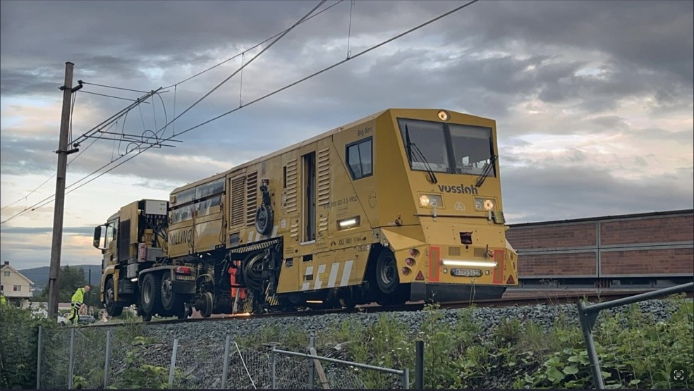
This chapter presents each machine group in a practical pattern: purpose, function or working method, what is checked or changed, and the result of the work. Table 17.1 gives the overall map before the individual machine types are described.
| Machine group | Purpose | Typical machines and outputs |
|---|---|---|
| Measurement vehicles | Condition control of railway infrastructure | ROGER 1000, SMV3, Sperry Rail unit; diagrams, defect lists and inspection data. |
| Rail surface treatment | Remove wear, corrugation and rail-head defects | Rail milling machines and rail grinding trains; restored profile and reduced roughness. |
| Track adjustment | Restore track and switch geometry | Tamping machines, lifting and lining units, switch tampers and dynamic track stabilisers. |
| Ballast machinery | Restore ballast profile, support and drainage | Ballast regulators, stabilisers, ballast cleaning machines, MFS wagons and ballast suction machines. |
| Renewal and construction | Replace or build track efficiently | Track renewal trains, portal cranes, road-rail machines, switch layers and switch-transport wagons. |
| Service machines | Keep the railway available and accessible | Maintenance trains, snow ploughs, snow brooms, rotary snow blowers and vegetation-control machines. |
Work machines on the Norwegian network must be approved by Bane NOR for operation on the relevant line class. Approval covers track compatibility (axle load and clearance profile), signalling and train-protection compatibility, communication and staff-safety arrangements, and performance for the intended task. The planning of each machine movement must also fit the possession or work-in-track arrangement used for the line.
17.2 Measurement Vehicles for Infrastructure Condition Control
Purpose. Measurement vehicles are used to assess the condition of the railway infrastructure and to increase safety. They turn measured condition into data that can be checked, trended and converted into work orders. The defects and geometry limits measured by these vehicles are introduced in Chapters 15 and 16; here the focus is on the machines and sensor platforms. Figure 17.2 shows the three vehicle examples used in this section.
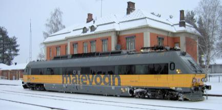
(a) ROGER 1000
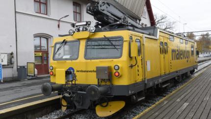
(b) SMV3
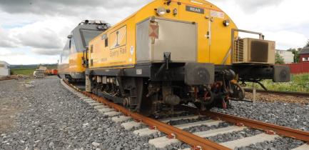
(c) Sperry Rail unit
Function and working method. The vehicles use sensors, cameras and measuring instruments to detect deviations, wear, missing components and other infrastructure defects. The control task is first defined by the infrastructure element being checked:
-
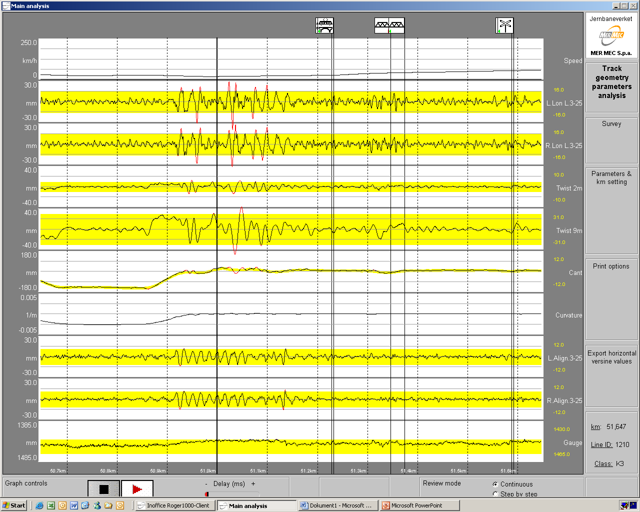
Track geometry: gauge, curvature, cant, twist, horizontal alignment and vertical level.
-
Superstructure components: rails, rail fastenings, sleepers and ballast.
-
Overhead contact line: contact-wire position and interaction with the pantograph.
-
Clearance profile: the free profile or minimum cross-section beside and above the track.
The vehicle choice follows the inspection task. ROGER 1000 records loaded track geometry, rail wear, corrugation and contact-line condition. SMV3 checks the clearance profile with a rotating laser and can support geometry measurement. Sperry Rail performs ultrasonic and eddy-current rail-flaw testing.
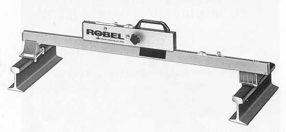
Track geometry control also has a loaded/unloaded distinction. The loaded case is measured by a vehicle such as ROGER 1000, where the track is recorded while it is loaded by the vehicle. A manual track gauge checks unloaded track, as shown in Figure 17.3. Both are useful, but they do not describe exactly the same condition.
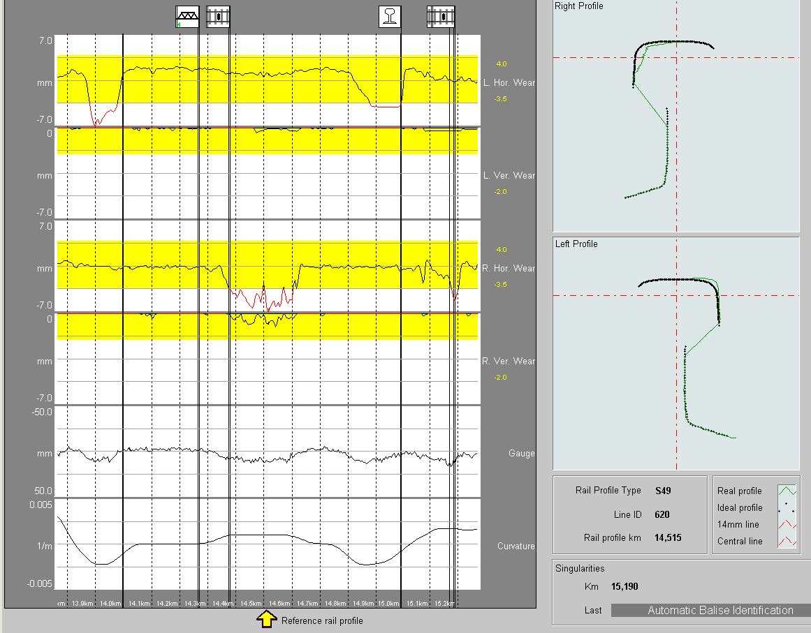
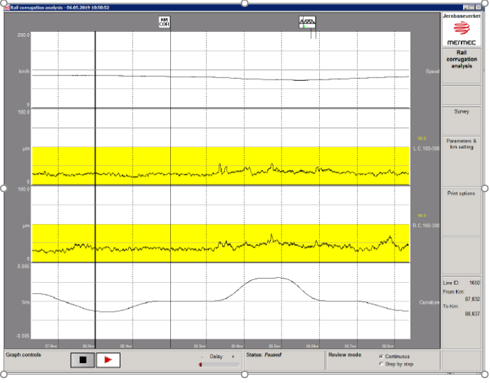
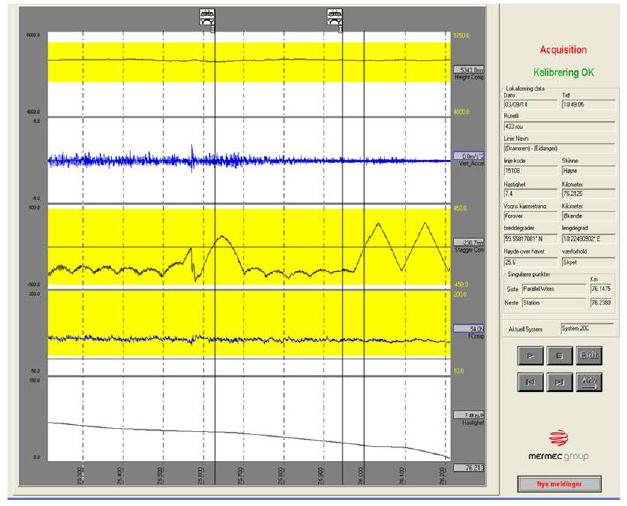
Result. The result is not only a measurement file. It is a set of diagrams, defect lists, images and database records that point to the next action. Figure 17.4 gathers examples of track-geometry traces, rail-profile and wear output, short-wave rail-head measurements, and overhead-line checks. These outputs decide whether the next task is tamping, rail milling, rail grinding, ballast cleaning, component repair or a more extensive renewal.
 (A) Track-geometry control
 (B) Rail-profile and wear output
 (C) Corrugation and short-wave output
 (D) Overhead-contact-line output
17.3 Rail Surface Treatment: Milling and Grinding
Rail surface treatment removes material from the rail head in a controlled way. The purpose is to remove corrugation, short waves, head checks, rail-head wear and other surface defects before they develop into noise, vibration, rolling-contact fatigue or premature rail replacement. This chapter focuses on the machines that carry out the treatment.
17.3.1 Rail Milling
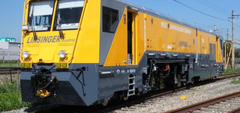
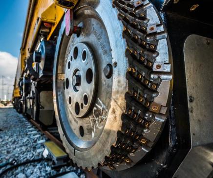
Purpose. Rail milling (skinnefresing) is used when the rail head needs accurate profile restoration or deeper material removal than ordinary preventive grinding. It is especially relevant where corrugation, squats, rolling-contact fatigue or profile defects have become too severe for light grinding alone. Figure 17.5 shows the rail milling train beside the cutter head, so the machine scale and the material-removal tool can be read together.
(a) Rail milling train
(b) Milling cutter head
Function and working method. A milling machine uses rotating cutter wheels to machine the rail head to a controlled transverse profile. The cutter head in Figure 17.5 removes material from the rail surface. The cut material is collected as chips rather than sparks and dust. A finishing grinding unit is often used after milling to remove cutter marks and improve the final running surface.
Result. The result is a restored rail profile with controlled material removal. Milling is slower and more specialised than ordinary grinding, but it can recover rails that would otherwise need heavy corrective grinding or replacement.
17.3.2 Rail Grinding
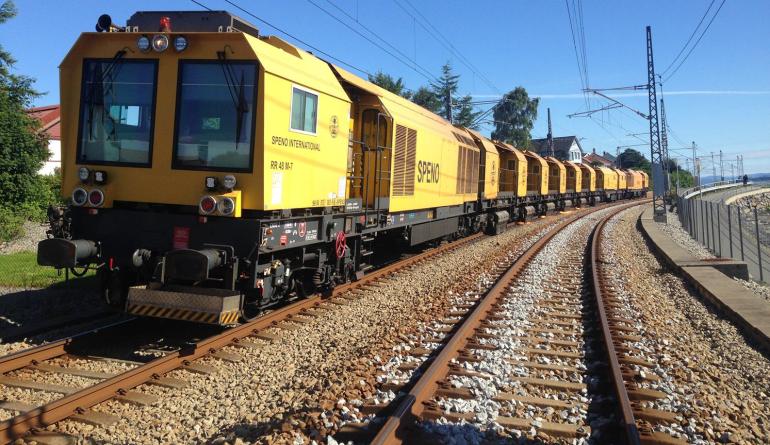
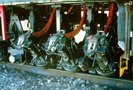
Purpose. Rail grinding (skinnesliping) removes rail-surface defects, reduces corrugation and roughness, improves wheel-rail contact and lowers noise and vibration. Grinding is therefore both a maintenance operation and a preventive measure against faster deterioration. Figure 17.6 shows the grinding train beside the grinding modules that work at the rail head.
(a) Rail grinding train
(b) Grinding modules
Function and working method. A grinding train carries rotating abrasive stones that are pressed against the rail head at controlled angles and contact forces, as shown in Figure 17.6. The grinding pattern defines which parts of the rail head are treated. A complete grinding programme may require several passes at different stone angles.
For possession planning, grinding intervals should be expressed in accumulated traffic as well as calendar time. Table 17.2 gives indicative planning values for strategy comparisons; the actual programme must always be set from measured rail profile, RCF depth, corrugation, curve radius, axle load and local noise requirements.
| Line type | Planning value | Interpretation |
|---|---|---|
| High-speed passenger, moderate axle load | 20–30 MGT; 0.1–0.2 mm per pass | Light preventive profile control; calendar interval depends strongly on annual MGT. |
| Heavy-haul or severe RCF environment | 5–10 MGT; 0.2–0.3 mm per pass | Shorter cycle, higher annual cost, but reduced risk of deep crack growth and premature rail replacement. |
Result. The result of milling or grinding is assessed by comparing the rail profile and rail-head roughness before and after the work. A good treatment removes the damaged surface layer while avoiding unnecessary rail-head loss.
17.4 Track Adjustment Machines
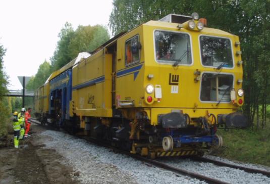
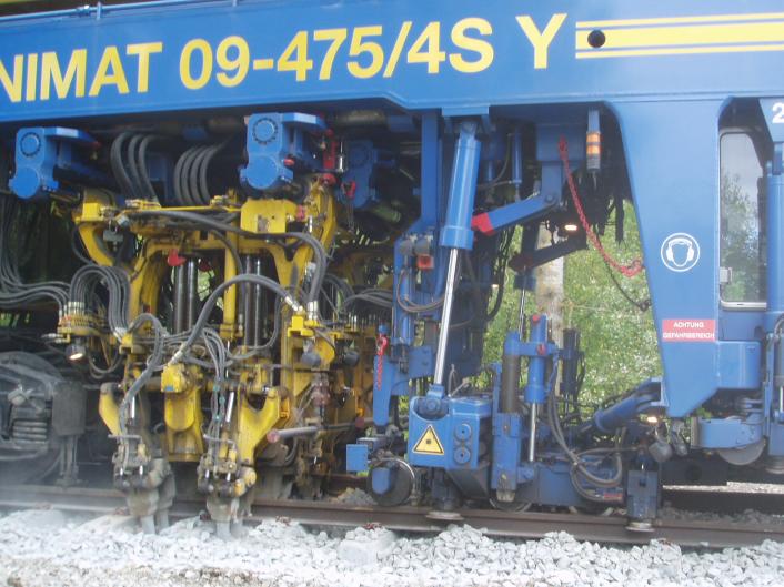
Track adjustment machines restore the vertical and horizontal geometry of track and switches. In Norwegian practice these are sporjusteringsmaskiner: machines for lifting, lining, packing/tamping and stabilising the track after the geometry correction. Figure 17.7 shows a track and switch adjustment machine beside the tamping unit that packs ballast under the sleepers.
(a) Track and switch adjustment machine
(b) Tamping unit working in ballast
17.4.1 Tamping and Track Geometry Correction
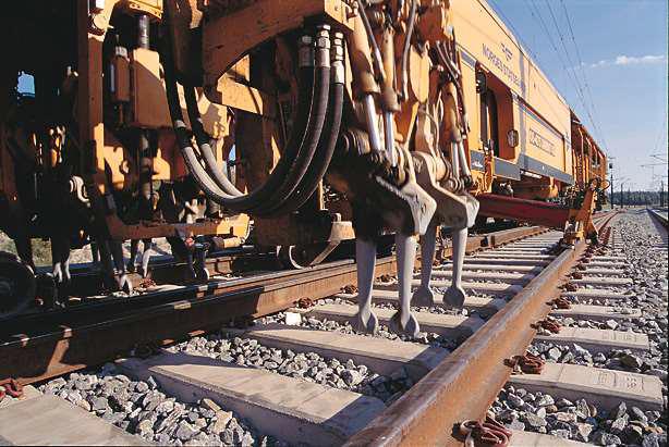
Purpose. Tamping machines are used to correct track position by lifting and lining the track and then packing ballast under the sleepers. They are used on plain line and in switches, but switch tamping requires machines or tamping units that can work around the more complex rail and sleeper arrangement. The tamping unit in Figure 17.7 shows the tools working in the ballast.
Function and working method. A tamping machine (pakkmaskin) is a self-propelled railway vehicle equipped with a geometry measurement system, lifting and lining units, and tamping tines. The lifting and lining unit in Figure 17.8 grips and moves the rails before the ballast is packed. The machine measures the current geometry, computes the required lift and line correction, raises and shifts the track, inserts vibrating tines into the ballast, and squeezes ballast under the sleepers.
The tamping unit consists of:
-
Lifting and lining claws that grip both rails and move the track to the computed position.
-
Tamping tines (pakkepinner) that vibrate and squeeze ballast under the sleeper.
The tamping principle in Figure 17.9 is a vertical sequence, so it is shown beside the step description rather than enlarged across the full page.
Sequence shown in the diagram:
-
Lift the sleeper and track panel to the corrected level.
-
Insert the vibrating tamping tines into the ballast.
-
Squeeze ballast under the sleeper.
-
Release the track supported in the corrected position.
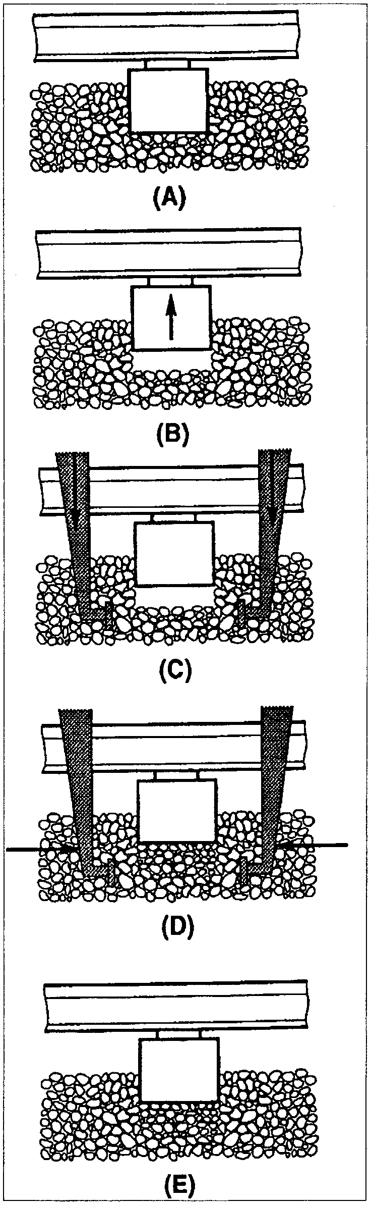
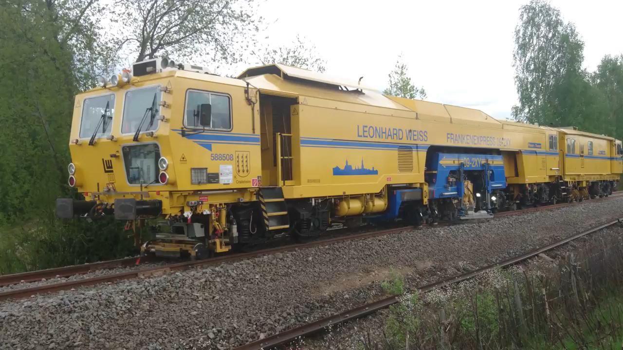
Result. The immediate result is improved track geometry. The side effect is that the ballast has been disturbed, so the track may need dynamic stabilisation, ballast profiling and sometimes a temporary speed restriction until the ballast has reconsolidated. A production tamping machine that combines these functions is shown in Figure 17.10.
| Parameter | Typical range | Comment |
|---|---|---|
| Working speed (plain line) | 1.5–4.0 km/h | Higher for multi-sleeper machines |
| Production rate | 800–2500 sleepers/h | Depends on machine type and site conditions |
| Tamping frequency | 35–45 Hz | Ballast compaction |
| Squeeze force per tine | 30–80 kN | Depends on ballast condition |
| Maximum lift | 40–60 mm | Per pass |
| Maximum lining | 30–40 mm | Per pass |
| Machine length | 20–35 m | Typical plain-line production machines |
| Machine mass | 60–120 t | Machine configuration dependent |
17.4.2 Ballast Distribution and Dynamic Stabilisation
Purpose. Ballast regulators restore the ballast profile after tamping or ballast supply. Figure 17.11 shows a rail-bound ballast regulator, while Figure 17.12 shows a road-rail regulator used where flexible access is needed. Dynamic track stabilisers reduce the settlement period after tamping by applying controlled vibration and vertical load to the track.
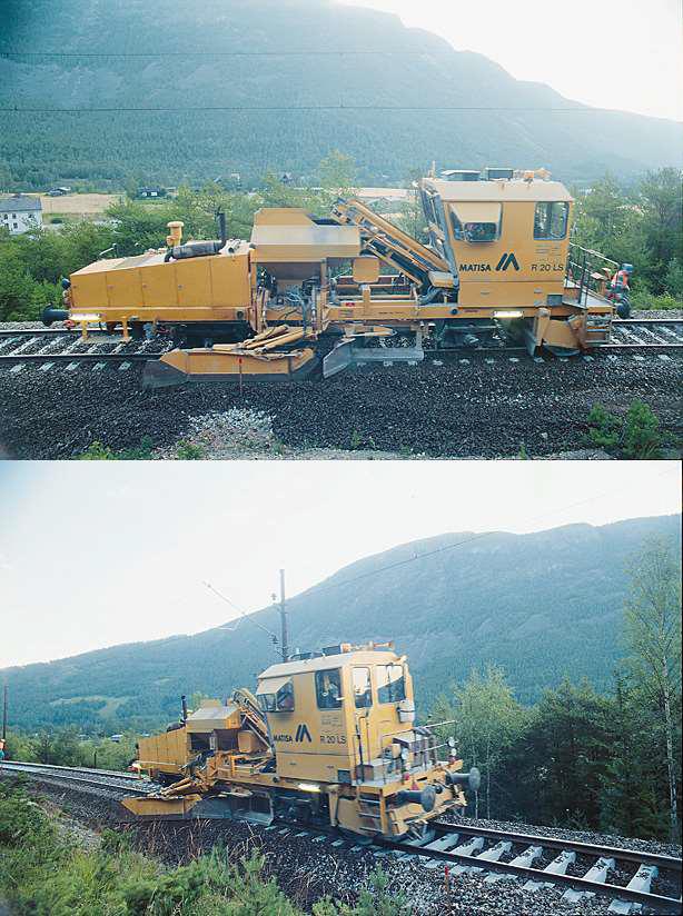
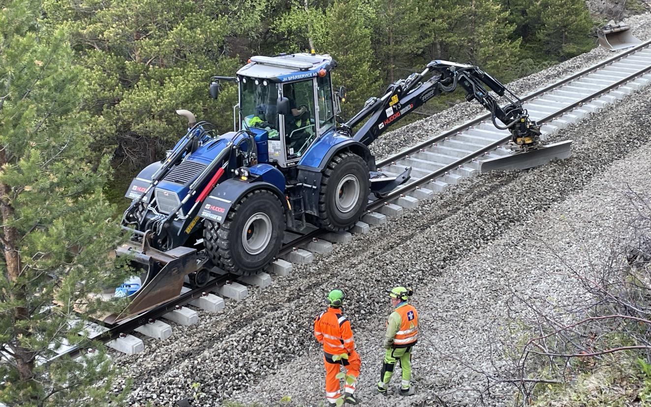
Function and working method. A ballast regulator uses plough blades and a rotary broom to distribute ballast into the cribs and shoulders and remove excess ballast from the track centre. A dynamic track stabiliser, shown in Figure 17.13, applies horizontal vibration while loading the track vertically. Figure 17.14 shows the stabilising principle: vertical load and horizontal vibration compact the ballast and increase lateral resistance.
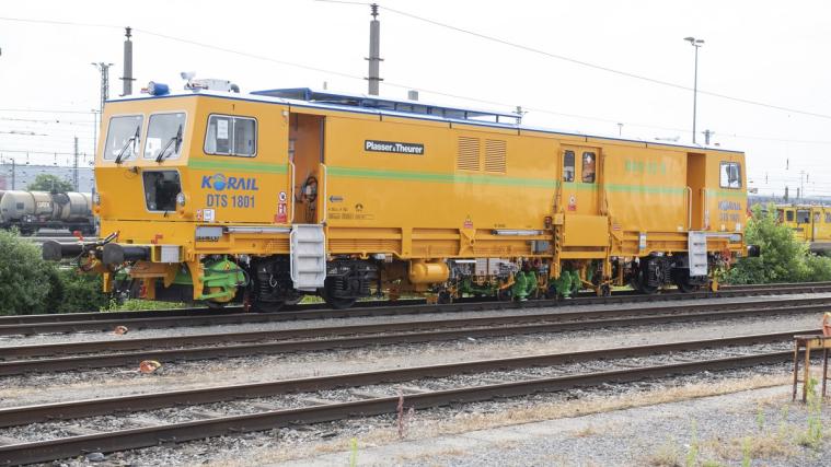
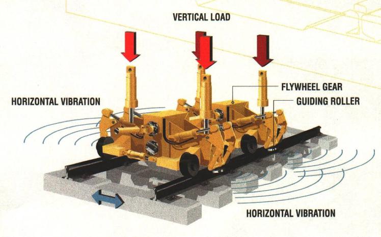
Result. Ballast regulation leaves the track profile ready for traffic and inspection. Stabilisation gives a more stable track immediately after tamping, which is important where rapid hand-back or high lateral resistance is required [124, 10].
17.5 Ballast Cleaning and Ballast Suction
Ballast machinery restores support and drainage. It is used when tamping and ballast regulation are no longer enough because the ballast is fouled, rounded, contaminated or missing from critical locations.
17.5.1 Ballast Cleaning Machines
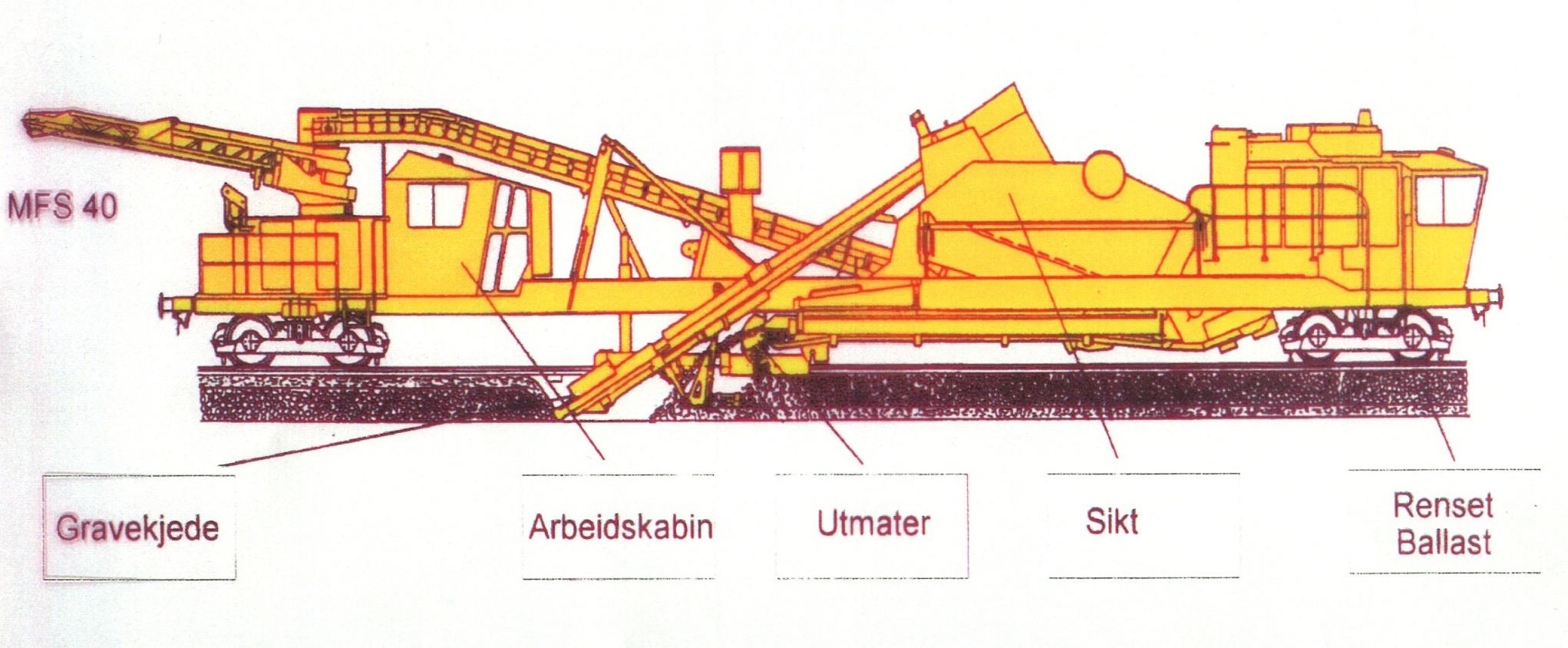
Purpose. A ballast cleaning machine (ballastrenseverk) removes fouled ballast, screens out fines and returns reusable coarse ballast to the track. The purpose is to restore drainage and ballast support without replacing all material. Figure 17.15 shows the work train, and Figure 17.16 shows a MATISA C75 ballast cleaner.
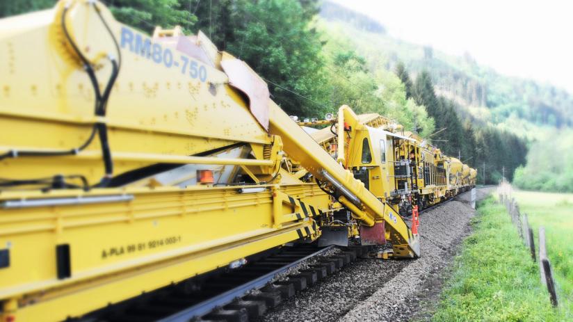
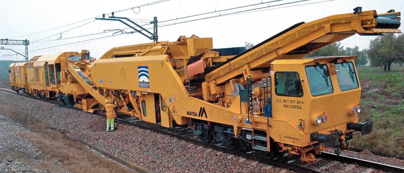
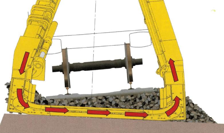
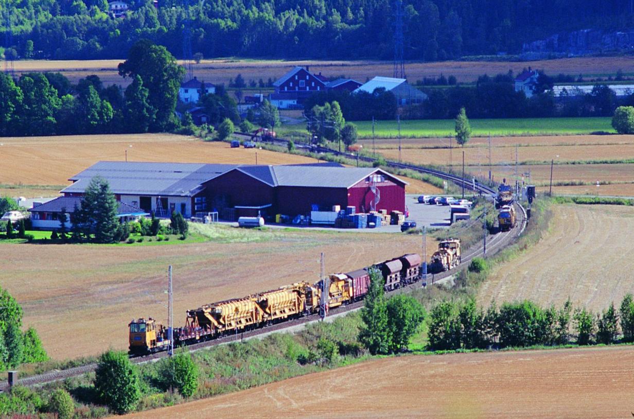
Function and working method. The process is shown schematically in Figure 17.17. The machine uses an excavating chain (gravekjede), shown in Figure 17.18, to remove ballast below and beside the sleepers. Conveyors move the material to vibrating screens. Clean coarse ballast is returned to the track, while fines and waste are moved to spoil wagons. A ballast cleaning operation often requires several machines at the same time: the cleaning machine, MFS or spoil wagons, locomotives, loaders and ballast-supply equipment. Figure 17.19 shows the scale of the supporting train and loader logistics.
| Parameter | Typical value |
|---|---|
| Working speed | 200–500 m/h (0.2–0.5 km/h) |
| Production rate | 200–600 m of track per shift |
| Excavation depth | 400–700 mm below rail foot |
| Screening capacity | 2000–4000 t/h |
| Machine length | 120–180 m (incl. spoil wagons) |
| Machine mass | 400–800 t (complete train) |
Result. The cleaned track has improved drainage and support. The limiting factor is often not the cleaning machine itself, but logistics: waste handling, return of reusable ballast, new ballast supply, work-train length and the available possession time.
17.5.2 Ballast Suction Machines
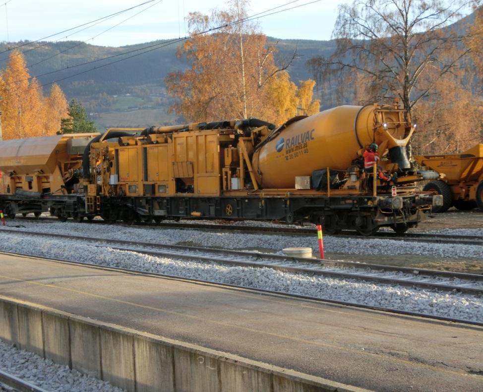
Purpose. Ballast suction machines (ballastsuger) are used where a full ballast cleaning train cannot work efficiently, especially in switches, platforms, drainage trenches and other confined areas. Figure 17.20 shows a rail-mounted suction machine.
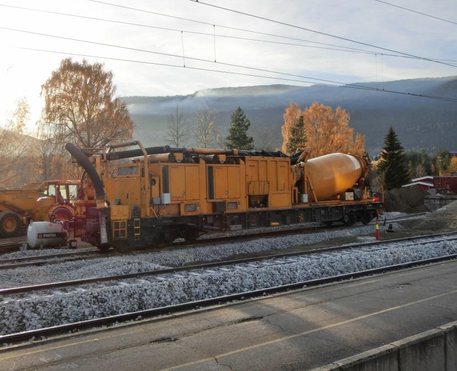
Function and working method. A suction machine works like a large railway vacuum cleaner. A hose removes ballast locally, often while the machine remains on the track. Figure 17.21 shows the vacuum tank and hose, while Figure 17.22 shows the large suction unit. The removed material is collected in a tank or wagon and transported away from the site.
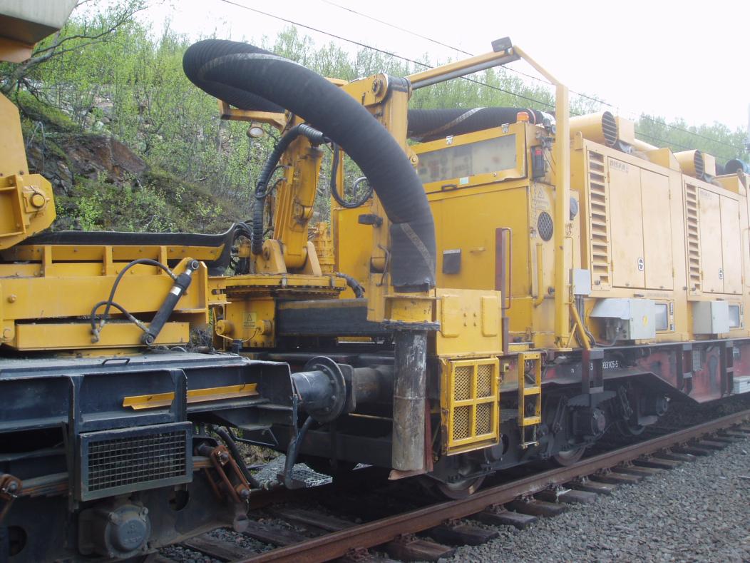
Result. Ballast suction gives precise local removal with less disturbance to neighbouring components than a full excavation train. It is slower than production ballast cleaning, but much more flexible in constrained locations. Figure 17.23 shows two typical local work situations: suction work in a switch area and suction work beside the track in a drainage trench.
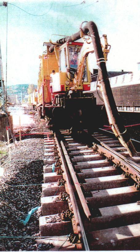
(A) Suction work in a switch area
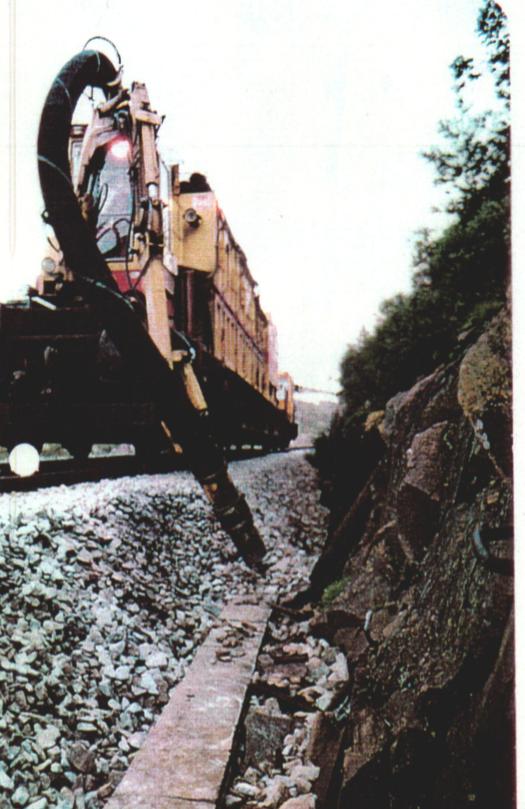
(B) Suction work in a drainage trench
17.6 Track Renewal and Construction Machines
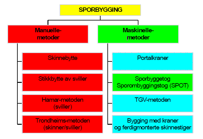
Renewal and construction machines are used when individual maintenance actions are no longer enough, or when new track is being built. The main groups are continuous renewal machines, panel or sleeper handling systems, switch installation machines and transport wagons for prefabricated switch panels. Figure 17.24 gives the method map used to distinguish manual and mechanised renewal methods.
17.6.1 Track Renewal Trains and Portal Cranes
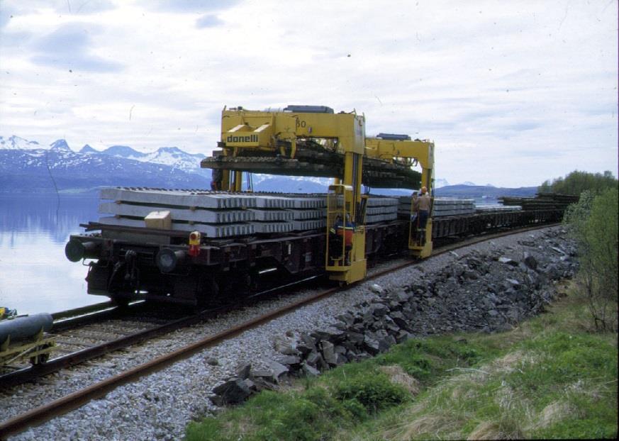
Purpose. Track renewal trains and portal-crane systems replace sleepers, rails or complete track panels with high output during a possession. They reduce the amount of manual handling and make renewal more predictable. Figure 17.25 shows portal cranes transporting sleepers, while Figure 17.26 shows a sleeper renewal train.
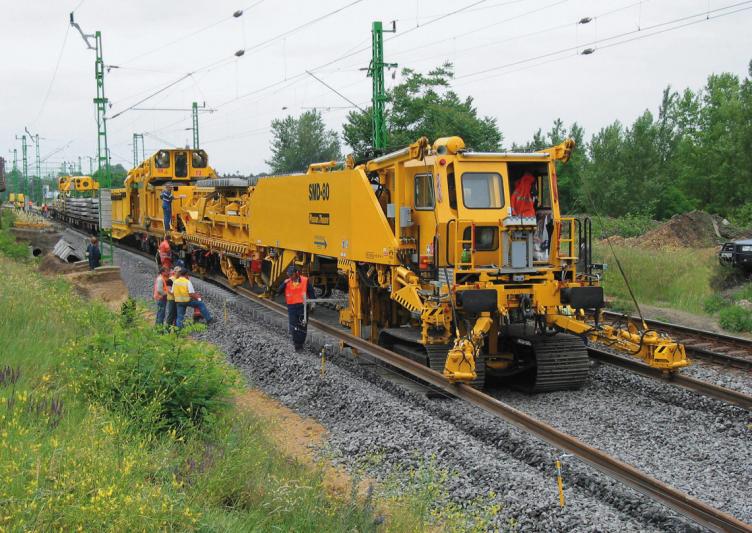
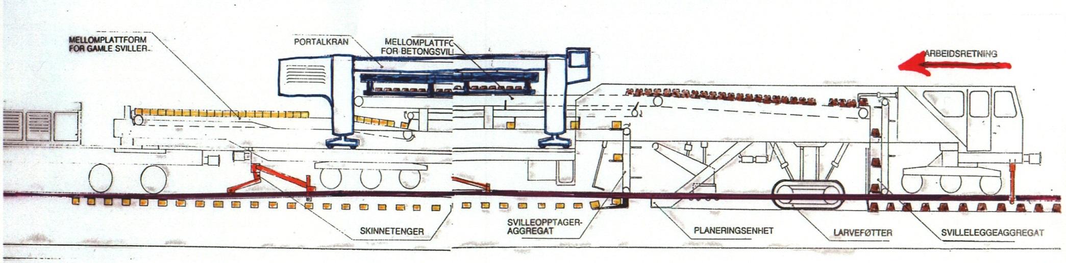
Function and working method. A renewal train can remove old components, prepare the ballast bed, place new sleepers or panels, thread rails and hand the track over for tamping, stabilisation and inspection. Figure 17.27 shows the sequence for sleeper renewal. Portal cranes can move sleepers or track panels along temporary rails or dedicated handling beams. Figure 17.28 shows track-panel construction, while Figure 17.29 shows a road-rail machine supporting renewal work with a cutting tool.
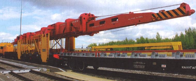
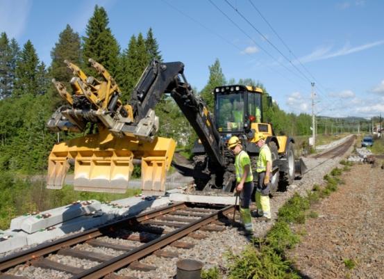
Result. The result is a renewed or newly built track section with a much higher production rate than isolated manual replacement. The work normally requires longer possessions, careful logistics and reliable supply of sleepers, rails, ballast and fastening material.
17.6.2 Switch Installation and Transport
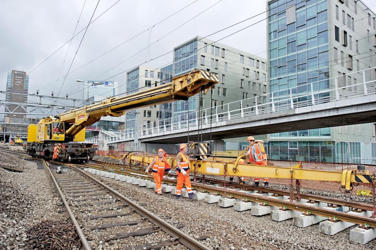
Purpose. Switches and crossings are heavy, geometrically precise assemblies. Special machines are used to transport, lift and install prefabricated switch panels without damaging the geometry. Figure 17.30 shows a DESEC switch layer, and Figure 17.31 shows switch installation with this machine type.
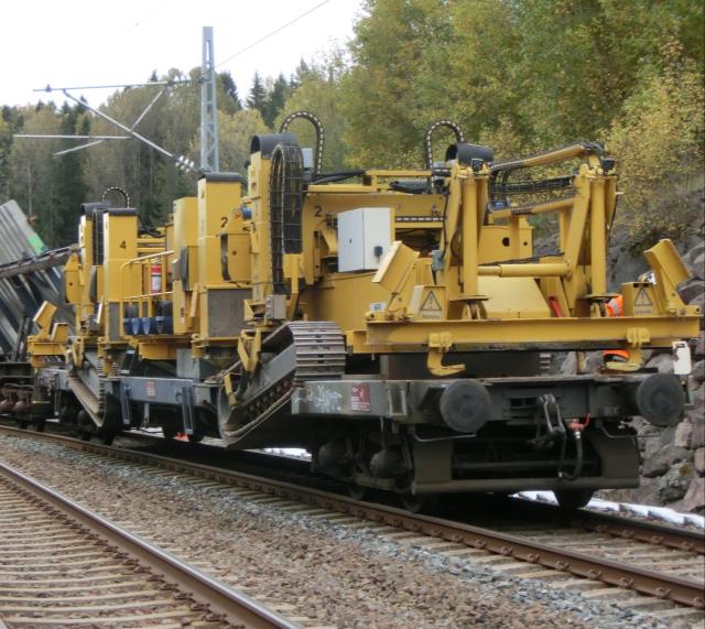
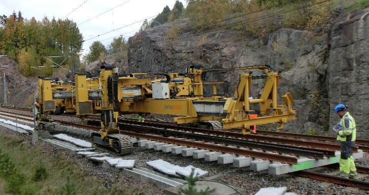
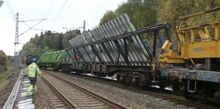
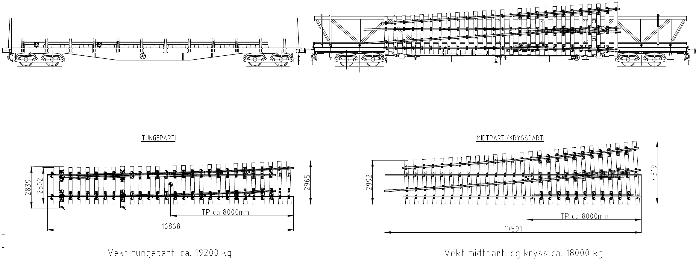
Function and working method. Switch layers such as DESEC machines and rail-bound cranes such as Kirow cranes lift switch panels into position using controlled lifting frames. Figure 17.32 shows a Kirow crane with lifting frame and a transport wagon carrying a prefabricated switch. Special wagons transport prefabricated switches so that factory-built geometry can be preserved until installation; Figure 17.33 shows the wagon schematic.
(A) Kirow crane and lifting frame
(B) Switch transport wagon
Result. Mechanised switch handling reduces installation time and improves quality, but it requires careful planning of crane positions, transport routes, possession length and temporary support of the switch panels.
17.7 Maintenance Train
Purpose. The maintenance train (vedlikeholdstoget) is a mobile work base for railway maintenance. It provides tools, storage, workshop functions and protected working areas close to the job site. Figure 17.34 shows the maintenance train as an exterior work vehicle.
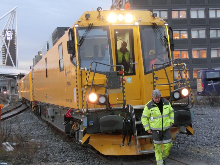
Function and working method. The train brings equipment, materials and personnel facilities to the possession. Figure 17.35 shows the workshop and storage area, while Figure 17.36 shows an interior work area. It can support several work types, including track component replacement, overhead-line work and smaller corrective tasks. The enclosed and protected work space in Figure 17.37 improves safety and makes the work less dependent on weather.
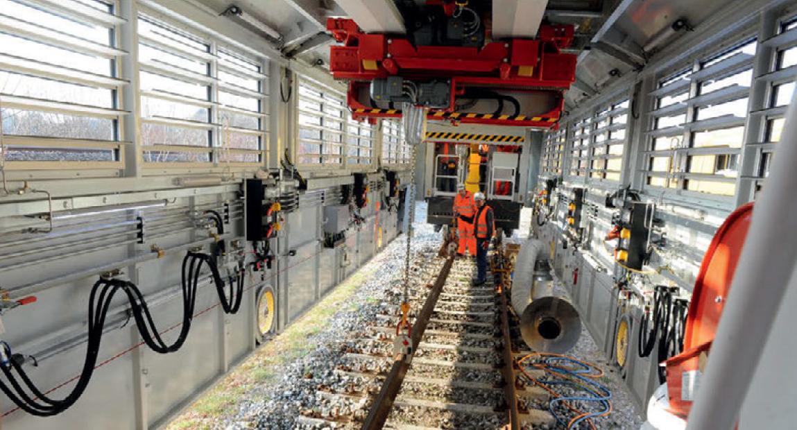
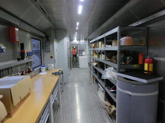
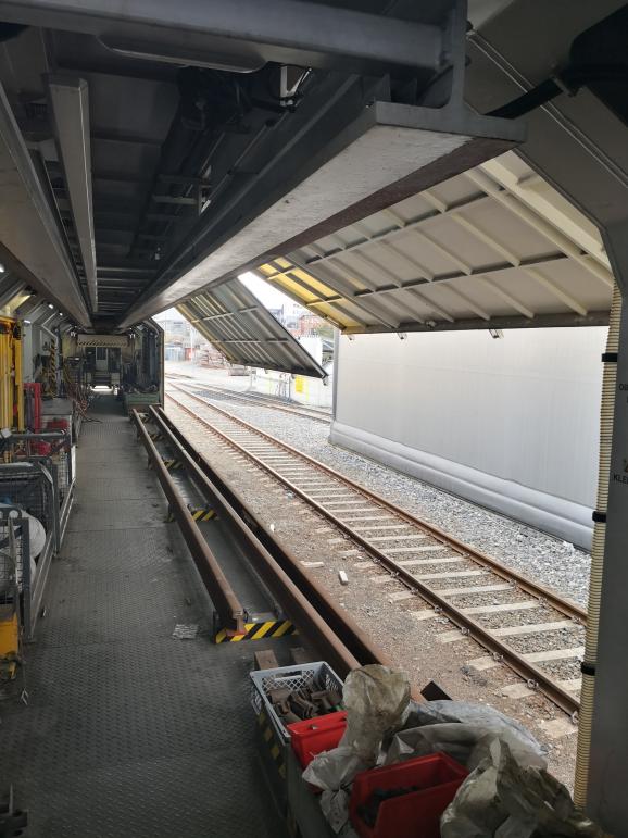
Result. The maintenance train improves efficiency for repeated smaller tasks because the tools and work environment travel with the crew. It does not replace specialist production machines, but it supports work that would otherwise require many separate vehicles and temporary site arrangements.
17.8 Winter Service and Vegetation Control
Railway machinery also includes machines that keep the railway available and accessible. Snow, ice and vegetation are operational problems as well as maintenance problems: they affect clearance, visibility, drainage, access for inspection and the risk of service disruption.
17.8.1 Snow Clearing Equipment
Purpose. Snow clearing equipment keeps the track, switches and clearance profile open during winter. The machine type depends on snow depth, snow density, available clearance, line speed and whether the snow must be thrown away from the track. Figure 17.38 shows snow clearing equipment with plough and broom functions.
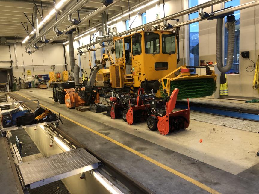
Function and working method. Snow ploughs push snow away from the track. Trailing snow ploughs and track cleaners clear the track area behind a traction unit. Snow brooms remove lighter snow from switches and track components. Rotary snow blowers remove deeper or harder snow by cutting it and throwing it away from the line. These working methods are shown together in Figure 17.39. Manual winter tools still appear in local clearing work, especially around switches and restricted locations, as shown in Figure 17.40.
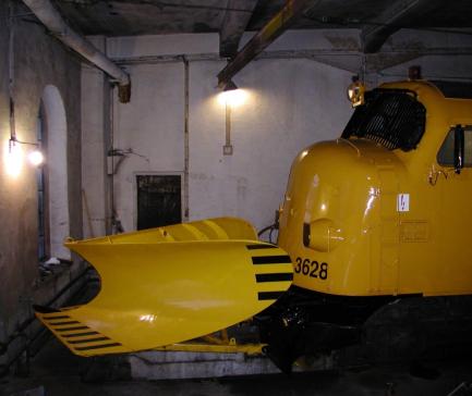
(A) Plough blade arrangement
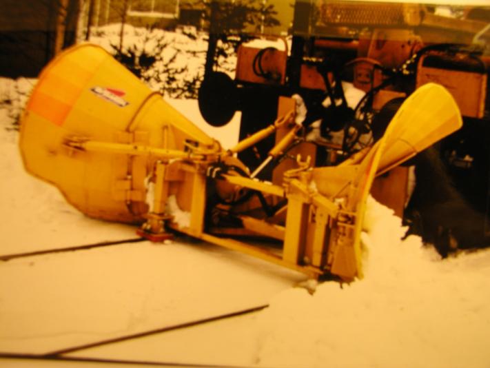
(B) Trailing snow plough
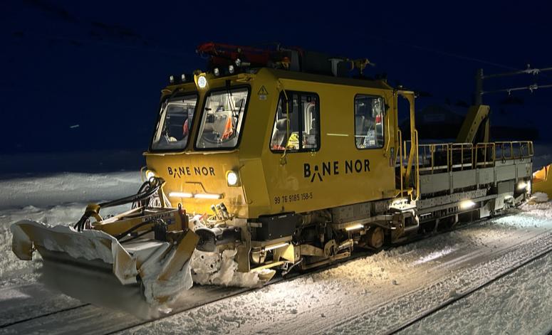
(C) Snow broom
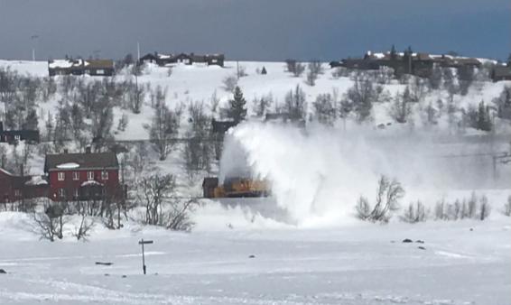
(D) Rotary snow blower
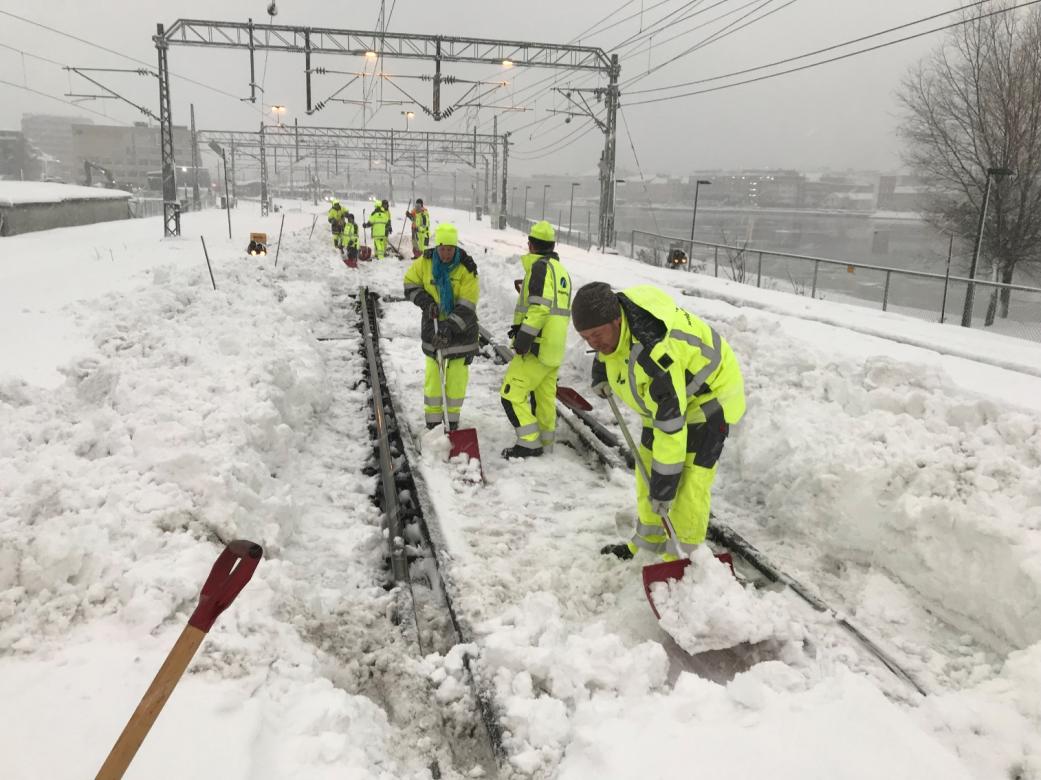
Result. The result is a usable track and a maintained clearance profile. Ploughs are fast but limited by snow depth and available space beside the track. Rotary snow blowers can remove more difficult snow but are slower and more specialised.
17.8.2 Vegetation Control
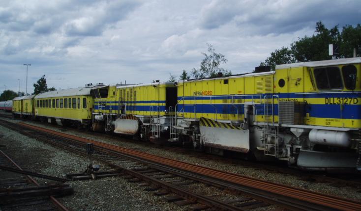
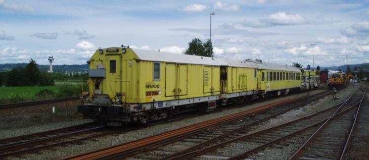
Purpose. Vegetation control keeps sight lines, drainage, access routes and the structure gauge clear. It also reduces leaf-fall problems, fire risk and obstacles for inspection and emergency access. Figures 17.41 and 17.42 show rail-bound vegetation-control equipment used along the track.
Function and working method. Vegetation can be controlled by rail-bound machines, road-rail machines and side-terrain equipment. The work may include cutting, flail mowing, removal of bushes and trees, and clearing around overhead-line structures. Figure 17.43 shows the side-terrain clearing concept, while Figure 17.44 shows a road-rail vehicle used for access and work near the overhead-line zone.
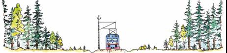
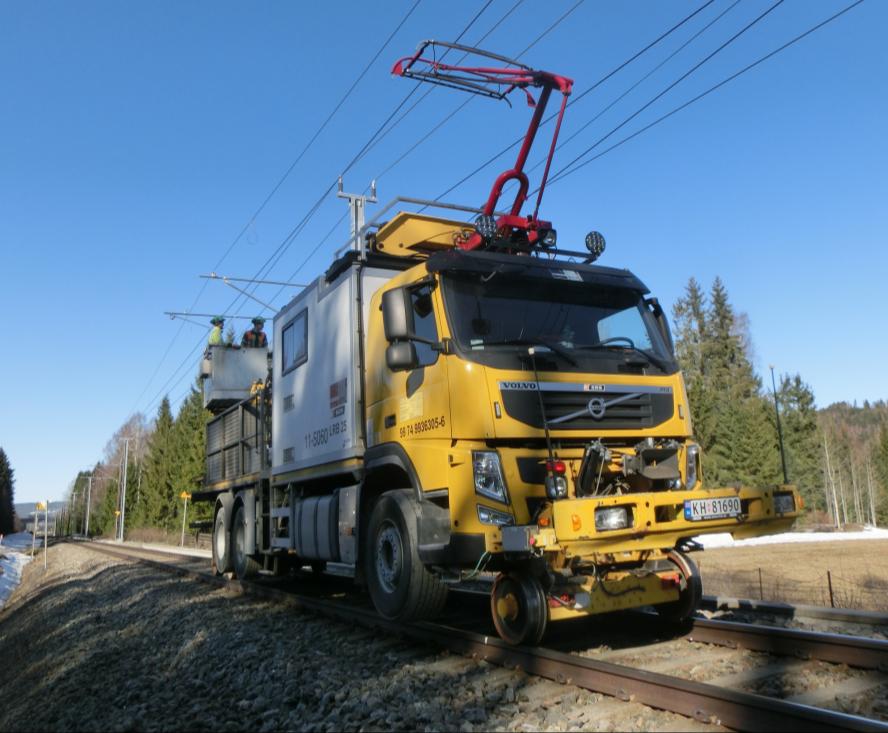
Result. The result is a safer and more maintainable railway corridor. Vegetation work must be planned with regard to traffic, overhead-line safety, environmental restrictions and the need to protect drainage and embankment stability.
17.9 Machine Planning and Operation
Machine planning converts the engineering need into a feasible work operation. The required machine is selected from the defect or work task: measurement vehicles identify the condition, treatment machines correct or remove the defect, renewal machines replace components, and service machines keep the railway available.
Machine productivity is measured in different units:
-
Measurement vehicles: kilometres inspected per run and number of parameters recorded.
-
Rail milling and grinding: kilometres per shift, number of passes and material removal.
-
Tamping: sleepers per hour, or kilometres of track per shift.
-
Ballast cleaning: metres of track per shift and tonnes of spoil removed.
-
Renewal machines: metres of track, sleepers, panels or switches per possession.
-
Winter and vegetation machines: treated kilometres, cleared area or availability effect.
These units cannot be compared directly. A high nominal machine speed does not help if set-up time, travel to site, spoil handling, material supply or hand-back inspection controls the possession. Table 17.5 therefore lists the planning unit used for each machine type instead of combining incompatible productivity measures in one chart.
| Machine type | Typical productivity measure | Planning note |
|---|---|---|
| Measurement vehicle | Kilometres inspected per run | Access is often easier than for production machines, but data processing and follow-up govern the value. |
| Rail grinding train | Working speed and number of passes | Output depends on grinding pattern, number of stones and required material removal. |
| Production tamper | Sleepers per hour or kilometres per shift | Strongly depends on plain line versus switch work and the amount of lifting/lining required. |
| Ballast cleaning machine | Metres per shift and spoil tonnes | Waste handling, ballast supply and work-train length often control output. |
| Renewal train or switch layer | Metres, sleepers, panels or switches per possession | Logistics, lifting plans and material supply are usually more limiting than machine movement speed. |
| Snow or vegetation machine | Treated kilometres or cleared area | Work is driven by weather, season, visibility, environmental limits and access. |
A track possession is a formally sanctioned period during which normal train operations on a defined section of track are suspended to allow work. In Norwegian operating terminology, the relevant work forms include disponering for arbeid, anleggsområde-jernbane, arbeidsbrudd on ERTMS lines, and avstengt område; the traffic-control action of blocking or securing the area is handled separately in the operating rules [22]. For planning, the important questions are simple: how long the machine needs, how it reaches the site, what supporting machines and materials are required, how the work is protected, and what must be inspected before the track is reopened.
17.9.1 Worked Example: Tamping Scope Within a Possession
Question. A production tamper is planned to correct 1200 sleepers during a 4.0-hour possession. Its nominal output is 900 sleepers/hour. The possession plan also requires 35 min for protection and travel to the work site, 25 min for machine set-up, 35 min for dynamic stabilisation, 25 min for geometry verification, and 20 min for hand-back. Is the scope feasible, and how many sleepers should be planned if a 30 min contingency is required?
Step 1: calculate nominal tamping time.
Step 2: calculate the complete possession demand. The non-tamping activities consume
The total planned time is therefore
The nominal margin in the 240 min possession is only
Step 3: impose the required contingency. Reserving 30 min leaves
so the robust production scope is
Engineering conclusion. The 1200-sleeper scope fits only nominally and provides 20 min rather than the required 30 min contingency. The planner should reduce the scope to approximately 1050 sleepers, extend the possession by at least 10 min, or demonstrate that one of the fixed activities can be shortened without weakening protection or hand-back quality. The same planning logic applies across machine groups, provided the productivity unit and possession checks are selected consistently.
17.10 Chapter Summary
Railway machinery. Railway machinery is broader than maintenance machinery. It includes measurement vehicles, surface-treatment machines, tamping and stabilisation machines, ballast machinery, renewal and construction machines, maintenance trains, and equipment for snow clearance and vegetation control.
Purpose and working method. Each machine group should be understood by its purpose, function, working method and result. Measurement vehicles find and document the condition. Treatment and adjustment machines correct the condition. Renewal and construction machines replace or build track. Service machines keep the railway available and accessible.
Planning. Machine output is meaningful only when it is expressed in the correct production unit. Grinding, tamping, ballast cleaning, switch installation, snow clearing and vegetation control cannot be compared on one speed scale. Possession time, travel, set-up, material supply, spoil handling, safety protection and hand-back requirements are often as important as the machine's nominal capacity.
Assignments
Assignment 1: Measurement vehicles and measured outputs
The images below show typical outputs produced by inspection and measurement vehicles.
(A) Track-geometry traces
(B) Rail-profile and wear output
(C) Corrugation and short-wave output
(D) Overhead-contact-line output
(a) Explain the purpose of measurement vehicles in railway infrastructure work.
(b) Match ROGER 1000, SMV3 and Sperry Rail to these inspection tasks: loaded track-geometry and contact-line control; clearance-profile and minimum-cross-section control; and ultrasonic or eddy-current rail-flaw testing.
(c) Identify what condition is represented by images A–D.
(d) For each image, give one maintenance or renewal task that the measured output could trigger.
Assignment 2: Rail surface treatment machines
The images and planning values below compare two rail surface treatment methods.
(A) Rail milling train
(B) Milling cutter head
(C) Rail grinding train
(D) Grinding modules
| Line type | Indicative planning value | Interpretation |
|---|---|---|
| High-speed passenger, moderate axle load | 20–30 MGT; 0.1–0.2 mm per pass | Light preventive profile control |
| Heavy-haul or severe RCF environment | 5–10 MGT; 0.2–0.3 mm per pass | Shorter cycle and larger material removal |
(a) Explain the difference between rail milling and rail grinding in purpose and working method.
(b) Describe what the cutter head in image B and the grinding modules in image D do at the rail head.
(c) Compare the two planning cases in the table: which case needs the shorter cycle, and which case removes more material per pass?
(d) Explain why rail profile and rail-head roughness are compared before and after milling or grinding.
Assignment 3: Track adjustment and ballast support machines
Tamping principle
| Parameter | Typical range |
|---|---|
| Working speed | 1.5–4.0 km/h |
| Production rate | 800–2500 sleepers/h |
| Tamping frequency | 35–45 Hz |
| Squeeze force per tine | 30–80 kN |
| Maximum lift | 40–60 mm per pass |
| Maximum lining | 30–40 mm per pass |
(a) Describe the tamping sequence shown in the diagram.
(b) Explain the roles of the lifting and lining claws and the tamping tines.
(c) Explain why ballast regulation and dynamic stabilisation may be required after tamping.
(d) Choose three parameters from the table and explain why each matters when planning tamping work.
Assignment 4: Ballast cleaning, ballast suction and renewal work
The images below show ballast cleaning and local ballast suction work.
(A) Ballast-cleaning process
(B) Excavating chain
(C) Suction work in a switch area
(D) Suction work in a drainage trench
(a) Explain when ballast cleaning is used and how the excavating chain, screens, conveyors and support equipment work together.
(b) Explain when ballast suction is preferred, using images C and D as examples.
(c) Compare ballast cleaning and ballast suction in terms of purpose, scale and site constraints.
(d) Choose two of these renewal or switch-installation machine types and describe the planning issue each one helps solve: sleeper renewal train, portal crane, DESEC switch layer, Kirow crane, or special wagon for prefabricated switches.
Assignment 5: Service machines and machine planning
(A) Maintenance train
(B) Winter-service equipment
(C) Vegetation-control train
| Machine type | Typical productivity measure |
|---|---|
| Measurement vehicle | Kilometres inspected per run |
| Rail grinding train | Working speed and number of passes |
| Production tamper | Sleepers per hour or kilometres per shift |
| Ballast cleaning machine | Metres per shift and spoil tonnes |
| Renewal train or switch layer | Metres, sleepers, panels or switches per possession |
| Snow or vegetation machine | Treated kilometres, cleared area or availability effect |
(a) Explain the purpose of a maintenance train.
(b) Give two winter-service machine types and two vegetation-control machine types or tasks.
(c) Choose suitable productivity measures for the machine groups in the table.
(d) Explain why these outputs cannot be compared on one speed scale, and list four possession-planning checks.