Continuously Welded Track
9.1 Introduction
The development of continuously welded rail (CWR) in track (helsveist spor) represents one of the most significant advances in railway engineering [65, 157]. In older conventional track, rails were normally installed as short bolted lengths, typically 10–40 m, connected by fishplates and bolts. From the Stockton–Darlington Railway of 1825 until World War II, jointed track was the normal form of main-line railway track.
The disadvantages of jointed track are significant:
-
Impact loads on the track at every joint, causing accelerated wear and fatigue on both track and rolling stock
-
The need for regular gap adjustment (to accommodate seasonal rail length changes)
-
Noise and vibration from trains crossing joints
-
Reduced passenger comfort
-
Wear on track components, rolling stock, and structures
-
Need for lubrication and inspection of joint bars
From 1945, CWR track began to replace jointed track. Today it is the standard for all main lines in Europe and most of the world [124, 12].
9.2 Definition of CWR Track
CWR track is defined as track where:
-
the rail length is so long that the central part of the rail cannot relieve temperature-induced stress by longitudinal movement
-
the free expansion and contraction that would occur in an unrestrained rail is largely prevented by the track panel, fastenings, and ballast
Per Norwegian regulations, a track with rails longer than 50 m must be treated and maintained as CWR track [12].
9.2.1 The Expansion Zone
In a CWR track, expansion and contraction due to temperature changes occur only in the expansion zones (pusteparti) at each end of the CWR section. In the central (locked) portion, large axial forces build up because longitudinal deformation is impossible. The equilibrium sketch in Figure 9.1 shows how longitudinal ballast resistance is mobilised over the breathing length at the rail end.
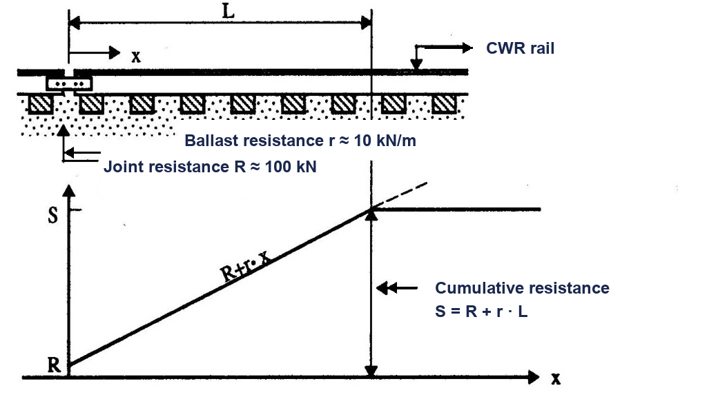
The length of the expansion zone depends on the track construction (rails, sleepers, fastenings, and ballast) and track condition. In Norwegian design guidance, typical breathing lengths are 50–100 m. The minimum rail length for a CWR section is therefore theoretically \(2 \times 50 = 100\) m [12].
The length of the expansion zone \(L\) is:
where \(P_\mathrm{rail}\) is the axial force in one rail to be transferred between the fixed CWR zone and the free end (kN), \(R_j\) is the residual resistance at the rail end or joint (kN), and \(r_\ell\) is the longitudinal track resistance per unit length for one rail (typically about 10 kN/m for well-compacted ballast). The mobilised resistance over the breathing zone is then \(r_\ell L\), so Eq. 9.1 is an equilibrium estimate, not a definition of the thermal force itself. For a well-stabilised track, \(L = 80\)–100 m.
Worked example.
If one rail must transfer \(P_\mathrm{rail}=500\) kN into the locked zone and the longitudinal ballast resistance is \(r_\ell=10\) kN/m per rail, the breathing length is
neglecting residual joint resistance. This is a per-rail calculation, so the per-rail resistance must be used.
9.2.2 The Track Panel
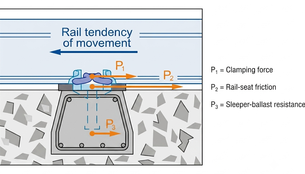
The resistance to longitudinal rail movement in CWR is provided by the track panel (skinnestige), the combined structural frame of rails and sleepers acting together. Three levels of longitudinal resistance act on the rail: fastening clamping force, rail-seat friction, and sleeper–ballast resistance. Figure 9.2 separates these three restraint mechanisms into \(P_1\) from the fastening, \(P_2\) from rail-seat friction, and \(P_3\) from the sleeper–ballast interface.
9.3 Advantages of CWR Track
CWR track offers significant operational and economic advantages over jointed track:
-
Reduced track maintenance costs (no joint maintenance)
-
Fewer rail defects and failures (no joint-induced fatigue cracks)
-
Extended rail lifetime (no bolted joints)
-
Reduced wear on superstructure, substructure, and rolling stock
-
Improved riding comfort
-
Reduced noise and vibration emissions
-
Lower energy costs for traction
-
Easier mechanisation of track installation and maintenance
The overall result is a reduced Life Cycle Cost (LCC) compared to jointed track. However, the elimination of expansion joints introduces a critical new risk: track buckling (sun kink) in summer and rail fracture in winter [65, 157].
9.4 Longitudinal (Axial) Forces in CWR
In continuously welded rail, temperature change is converted into axial force because the rail cannot freely expand or contract. The following derivation establishes the basic force relation used throughout the chapter.
9.4.1 Thermal Forces
When a rail that is restrained from expanding is subject to a temperature increase \(\Delta t\), a compressive force builds up. When the temperature falls, tensile forces develop. The derivation combines Hooke's law with the thermal expansion equation. Consider a rail of cross-sectional area \(A\), elastic modulus \(E\), and linear thermal expansion coefficient \(\alpha\). If the rail is fully restrained (prevented from expanding or contracting) and the temperature changes by \(\Delta t\), the strain that would occur in a free rail is:
Since the rail is restrained, this strain is converted entirely into mechanical stress via Hooke's law \(\sigma = E\,\varepsilon\). The induced thermal stress is therefore:
Multiplying by the cross-sectional area gives the axial force in one rail:
Substituting the material properties of rail steel (\(\alpha = 1.15\times10^{-5}\,\mathrm{K}^{-1}\), \(E = 2.1\times10^5\,\mathrm{N\,mm^{-2}}\)):
The derived results are summarised above (Eqs. 9.3 and 9.4), where \(\alpha = 1.15 \times 10^{-5}\,\mathrm{K}^{-1}\) is the coefficient of thermal expansion of steel, \(E = 2.1 \times 10^5\,\mathrm{N\,mm^{-2}}\) is the elastic modulus, and \(A\) is the rail cross-sectional area in \(\mathrm{mm}^2\). In the practical form \(P_\mathrm{rail}\approx2.4\,\Delta t\,A\), use \(\Delta t\) in kelvin, \(A\) in \(\mathrm{mm}^2\), and the resulting \(P_\mathrm{rail}\) is in newtons.
The key insight is that the force in a restrained rail depends only on the temperature change and the cross-sectional area, not on the length of the rail. The total force in the two rails is \(P_\mathrm{tot}=2P_\mathrm{rail}\), so larger rail profiles develop larger restrained force for the same temperature change.
Worked example.
A 60E1 rail has \(A = 7686\,\mathrm{mm}^2\). If the rail temperature is \(25\,^\circ\mathrm{C}\) above the stress-free temperature (\(\Delta t=25\,\mathrm{K}\)), the compressive force in one rail is
The total compressive force in both rails is therefore \(P_\mathrm{tot}=2P_\mathrm{rail}=922\,\mathrm{kN}\). If the temperature were \(25\,^\circ\mathrm{C}\) below the stress-free temperature, the magnitude would be the same but the force would be tensile.
| Profile | \(A\) [\(\mathrm{mm}^2\)] | \(2P\) [\(\Delta t{=}1\,\mathrm{K}\)] | \(2P\) [\(\Delta t{=}25\,\mathrm{K}\)] |
|---|---|---|---|
| 49E1 | 6297 | 30.2 kN (3.0 tf) | 755 kN (76 tf) |
| 54E3 | 6948 | 33.4 kN (3.3 tf) | 834 kN (83 tf) |
| 60E1 | 7686 | 36.9 kN (3.7 tf) | 922 kN (92 tf) |
Approximate tonne-force equivalents use \(1\,\mathrm{tf}=9.80665\,\mathrm{kN}\approx10\,\mathrm{kN}\).
9.5 Neutral Temperature
Neutral temperature is the reference state for assessing whether CWR is in compression or tension. Small changes in this reference can strongly affect buckling and fracture risk.
9.5.1 Definition
The neutral temperature \(T_n\) (nøytraltemperatur) is the target stress-free rail temperature chosen in design and construction. At this temperature the rail is intended to be neither in compression nor tension. In service it is often useful to distinguish this target value from the actual stress-free temperature \(T_{sf}\), which can drift because of rail creep, lateral realignment, welding, or maintenance work.
where \(T_m\) is the mean rail temperature at the site and \(X\) is a shift (typically \(0\)–\(10\,^\circ\mathrm{C}\)) to balance the asymmetric temperature range. The neutral temperature is achieved during installation by:
-
Laying the rail at the exact neutral temperature, or
-
Heating the rail to its neutral temperature before fastening, or
-
Mechanically stretching (tensioning) the rail to introduce the equivalent elongation before fastening
9.5.2 Bane NOR Requirements
Nordic administrations use different neutral-temperature targets and tolerance bands. These values define the stress-free reference state used in the following discussion: a deviation from the intended neutral-temperature band changes the balance between winter tension and summer compression [6, 157].
| Administration | Neutral temperature [\(^\circ\)C] | Tolerance [\(^\circ\)C] |
|---|---|---|
| Trafikverket | \(+10\) to \(+20\) | \(-3/+7\) |
| Väylä | \(+17\) | \(\pm 5\) |
| Banedanmark | \(+22\) | \(\pm 7\) for \(V \leq 200\) km/h; \(\pm 3\) for \(200 < V \leq 250\) km/h |
| Bane NOR | \(+21\) | \(\pm 3\) |
9.5.3 Consequences of Deviation from Neutral Temperature
If the actual stress-free temperature \(T_{sf}\) deviates from the designed \(T_n\):
-
\(T_{sf} > T_n\): increased tensile forces in winter \(\Rightarrow\) risk of rail fracture (skinnebrudd)
-
\(T_{sf} < T_n\): increased compressive forces in summer \(\Rightarrow\) risk of track buckling / sun kink (solslyng)
9.6 Sources of Additional Forces in CWR
Thermal loading is not the only source of axial force in CWR. Maintenance activities, train actions, turnouts, and bridges can all shift the stress-free state.
9.6.1 Lateral Shift of Track Alignment
When the track in a curve is shifted laterally (e.g., by tamping for geometry correction), the stress-free temperature changes because the rail arc length changes:
where \(\Delta R\) is the inward radial shift of the track centreline and \(\alpha\) is the coefficient of thermal expansion of rail steel. The expression follows from equating the curvature-induced rail-length change to an equivalent free thermal strain.
Figure 9.3 quantifies the effect of lateral shift by relating side movement, curve radius, and equivalent stress-free-temperature change. A shift inwards (towards the centre of curvature) reduces the arc length, which is equivalent to reducing \(T_{sf}\), thereby increasing compressive forces. A 10 cm inward lateral shift in a curve with \(R = 300\) m reduces the stress-free temperature by \(28\,^\circ\mathrm{C}\), a very significant effect. An outward shift has the opposite sign: it raises the stress-free temperature and therefore increases the risk of winter tensile fracture. The sign convention is important: ordinary geometry correction can unintentionally change the stress state even when no rail is cut.
![Bane NOR graph of neutral-temperature change versus lateral track shift [15].](../../assets/chapters/ch09/original/figures_hq/fig_lateral_shift_chart_banenor_english_labels.jpg)
9.6.2 Rail Creep
When trains brake or accelerate, longitudinal forces up to 260 kN (approximately 26 tf, measured in the USA) are transferred to the rails [15]. The cumulative effect of these repeated forces causes rail creep (skinnevandring): a slow net displacement of the rail relative to the sleepers. Rail creep can shift the stress-free temperature by approximately \(10\,^\circ\mathrm{C}\) and causes skewed sleepers. Rail anchors (skinnestoppere) are installed to resist creep.
9.6.3 Turnouts (Switches and Crossings)
Turnouts create additional longitudinal forces because they act as semi-fixed points in the rail. The axial forces in stock rails are locally increased in the switch part. Technical regulations therefore require special attention to welding sequence, neutralisation, and the longitudinal position between switch rail and stock rail when a turnout is welded into CWR [10, 12].
9.6.4 Bridges
Long bridges create additional forces in CWR because the bridge deck expands and contracts independently of the rails [156, 65, 10]. Typical threshold lengths requiring an expansion device or special track–bridge interaction assessment are:
-
Steel bridge (no ballast): dilatation length \(> 100\) m
-
Steel bridge with ballast: \(> 90\) m
-
Concrete bridge: \(> 120\) m
For shorter bridges (10–100 m on steel bridges), railfree fastenings (befestigelse som tillater fri lengdebevegelse, e.g., Pandrol e2071 Railfree) allow the rail to slide freely relative to the bridge deck, preventing excessive force build-up. The practical distinction is shown in Figure 9.4: railfree fastenings maintain continuous rail through the bridge detail, while an expansion joint introduces a controlled movement gap where larger relative movement must be accommodated.
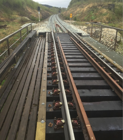
(a) Railfree bridge fastening
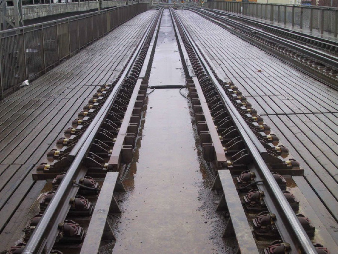
(b) Bridge expansion joint
9.7 Lateral Track Resistance (LTR)
Lateral track resistance is the main stabilising force against sideways movement of CWR. It depends on the combined contribution of rails, fastenings, sleepers, ballast profile, and ballast consolidation.
9.7.1 Definition
The Lateral Track Resistance (LTR) is the resistance of the track panel and ballast against cumulative lateral displacement. It is the key parameter governing the safety of CWR track against buckling, and its resistance comes from four main contributions:
-
Rail bending stiffness (horizontal/lateral second moment of area, not the vertical bending inertia used for rail-seat bending)
-
Fastening torsional resistance: clamping force, rail seat dimensions, pad friction, worn pads and insulators significantly reduce LTR
-
Sleeper–ballast lateral resistance: bottom friction (40 %), sleeper end resistance (35 %), sleeper shoulder resistance (25 %)
-
Ballast quality and profile: shoulder width, crib filling, ballast grain size, degree of consolidation
9.7.2 Effect of Track Maintenance on LTR
Maintenance actions can temporarily reduce the sleeper–ballast contribution to LTR, while consolidation and stabilisation gradually restore resistance. Table 9.3 compiles typical influence ranges from Bane NOR side-resistance guidance and lateral-resistance literature; the values should be treated as approximate because they depend on track class, ballast condition, sleeper type, and measurement method [17, 123].
| Factor | Effect on LTR | Comment |
|---|---|---|
| Rail bending stiffness \(I_y\) | \(-5\) to \(+4\) % | Usually secondary to ballast and sleepers |
| Fastening torsional resistance | \(+10\) to \(+20\) % | Depends on clamp condition and rail-seat friction |
| Sleeper material: concrete vs. timber | \(+40\) to \(+80\) % | Dominant factor |
| Reduced sleeper spacing | \(+5\) to \(+10\) % | More sleeper–ballast contact per metre |
| Tamping | \(-30\) to \(-50\) % | Temporary reduction |
| Ballast cleaning | \(-50\) to \(-70\) % | Fines removal |
| Track adjustment / ballast disturbance | \(-50\) to \(-60\) % | Especially critical in warm weather |
| Ballast compaction (DTS) | \(+20\) to \(+40\) % | Post-tamping recovery |
| Safety clips / tension clamps | \(+30\) to \(+40\) % | Fastening contribution |
| Crushed vs. rounded ballast | \(+30\) % | Interlock effect |
| Reduced ballast shoulder | \(-10\) to \(-55\) % | Geometry-dependent |
| Dynamic uplift (passing axle) | \(-30\) % | Transient unloading |
After tamping, the LTR may drop to about half of its pre-tamping value. Recovery occurs gradually as traffic loads consolidate the ballast. For preliminary calculations, the stabilising effect of a Dynamic Track Stabiliser (DTS) is often treated as approximately equivalent to 100,000 GT (0.1 MGT) of traffic consolidation; the machine arrangement is shown later in Chapter 17, Figure 17.13. The actual recovery depends on ballast condition, sleeper type, lift and lining magnitude, and traffic loading.
9.7.3 Dynamic Uplift
A critical but often underestimated factor is dynamic uplift: the vertical unloading of the track that occurs in the track section ahead of and behind an axle due to the wave of elastic deflection. Figure 9.5 links this axle-induced vertical movement to the temporary reduction in dynamic lateral resistance.
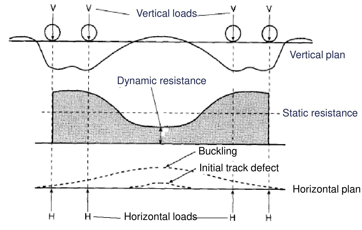
In the loaded-tie idealisation, dynamic lateral resistance is the static lateral resistance plus the frictional contribution generated by the effective vertical load [117]:
where \(F_D\) is the dynamic lateral resistance, \(F_S\) is the non-frictional part of the lateral resistance, \(\mu\) is the sleeper–ballast friction coefficient, and \(V\) is the effective vertical load. Dynamic uplift reduces \(V\) in Eq. 9.7, so it also reduces the available lateral resistance. An uplift of just 1 mm can reduce LTR substantially, which is one reason why speed restrictions are imposed on freshly tamped CWR track.
9.7.4 Required LTR: The \(q = P/R\) Criterion
The minimum required lateral resistance per unit track length \(q\) to prevent buckling in a curve of radius \(R\) is derived from equilibrium of the curved rail:
Laboratory tests reported for standard and friction sleepers, together with ERRI/Bane NOR summaries of sleeper-type effects, show that available lateral resistance depends strongly on vertical load and sleeper type [130, 17]. This matters before the simplified \(q=P/R\) equilibrium check is applied, because the resistance used in the check is not a fixed material constant; Figure 9.6 gives representative measured trends.
![Measured lateral resistance versus vertical load for selected sleeper types [130, 17].](../../assets/chapters/ch09/original/figures_lecture_crops/fig_lateral_resistance_lab_tests_crop.jpg)
Here \(P_\mathrm{tot}\) is the total compressive force in the two rails and \(q_\mathrm{tot}\) is the total lateral track resistance per metre for the track panel. If a per-rail resistance is used instead, use \(P_\mathrm{rail}\) and \(q_\mathrm{rail}\) on both sides of the same check. The result is physically the same, but mixing total force with per-rail resistance gives an erroneous factor of two. This formula shows that the tightest curves require the highest LTR [65, 157]. This is why tighter ballast profiles, heavier sleepers (BNF60 friction sleepers), and shorter sleeper spacing are required in curves, and why CWR is not permitted below minimum curve radii without special measures.
Worked example.
Assume a curve with \(R=400\) m and a total compressive force in both rails of \(P_\mathrm{tot}=720\) kN. The required total lateral resistance is
If the pre-tamping total LTR is 10 kN/m and tamping reduces it to 45 %, the available total resistance is \(0.45\times10=4.5\) kN/m. Since \(4.5>1.8\) kN/m, the simple equilibrium check is satisfied. Speed restrictions may still be needed because dynamic uplift, alignment defects, and freshly disturbed ballast are not included in the check.
9.8 Track Buckling (Sun Kink)
Track buckling is the critical summer failure mode for CWR under high compression. The following definition gives the practical threshold before discussing causes and prevention.
9.8.1 Definition
Track buckling, known in Norwegian as solslyng, is defined by Bane NOR as: a lateral displacement of the track more than 25 mm measured by a chord of 10 m, caused by compressive longitudinal forces in the rails [48]. Figure 9.7 shows the field measurement principle for identifying the lateral arch over the 10 m chord.
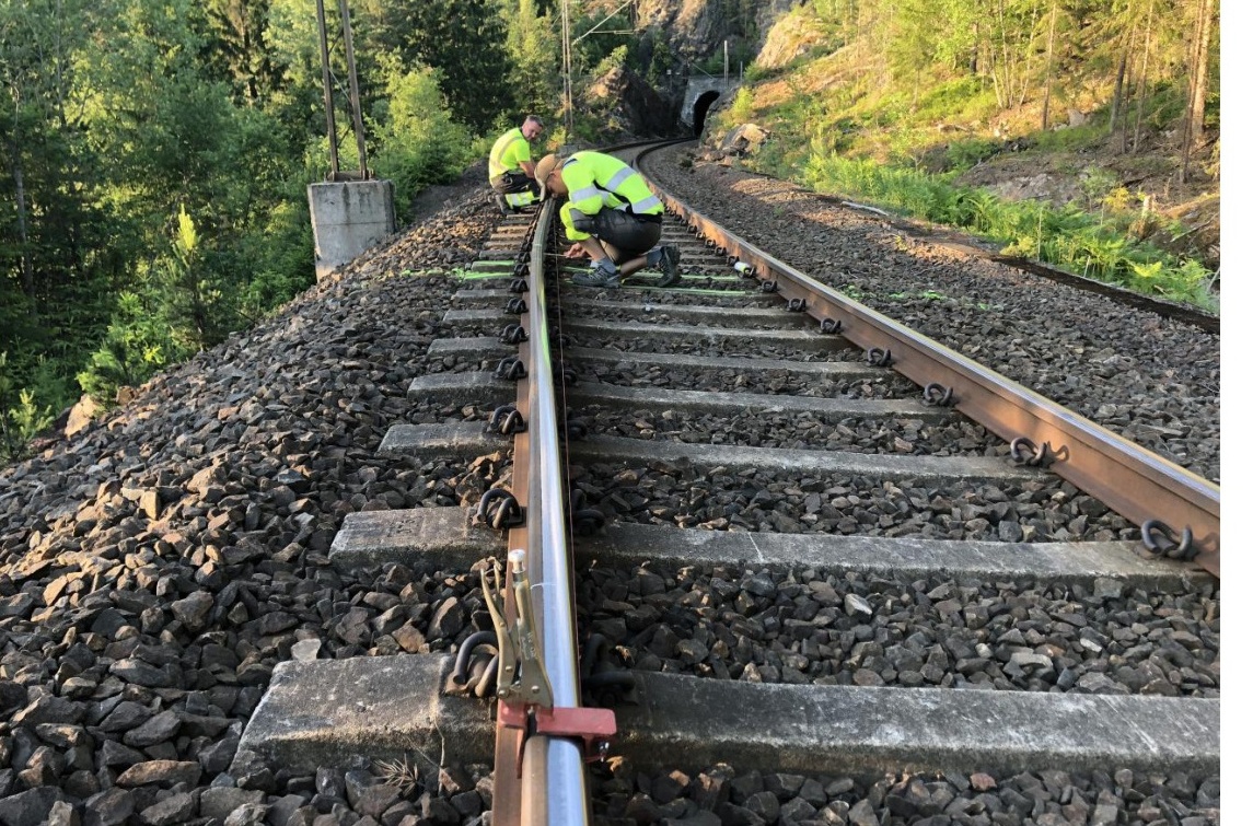
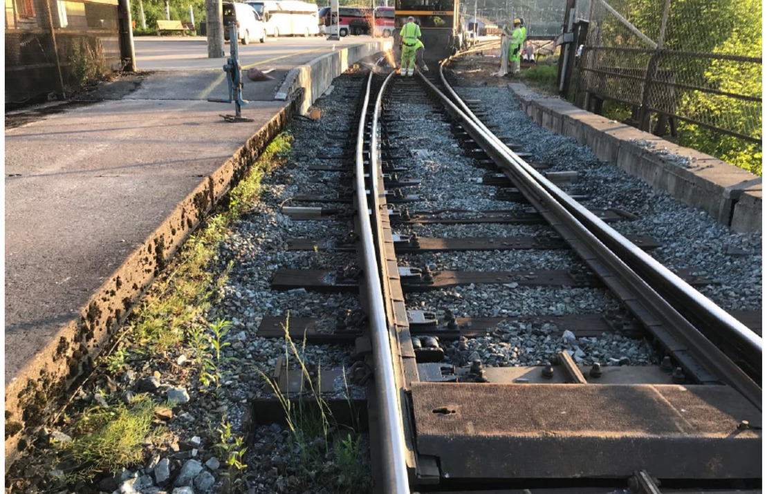
Figure 9.8 shows a field example of track buckling at Hønefoss, where the lateral track displacement is visible through the turnout area.
Track buckling is particularly dangerous because:
-
It presents a high risk of derailment
-
It is very difficult to predict because continuous, direct in-service measurement of rail force is not normally available
-
A passing train can trigger the buckling
9.8.2 Factors Increasing Buckling Risk
Elements that reduce LTR or increase compressive forces:
-
Too small ballast profile (narrow shoulders, insufficient crib filling)
-
Fouled ballast (reduced internal friction)
-
Track maintenance work (tamping, ballast cleaning), critical in warm weather
-
Dynamic uplift from passing trains (reduces LTR by up to 40 %)
-
Vibrations from trains loosening ballast (rail corrugation)
-
Track geometry defects (misalignments, settlement-induced defects)
-
Loose or worn fastenings, cracked concrete sleepers
-
Lateral shift during tamping at low temperatures
-
Rail creep changing the stress-free temperature
-
Insufficient track neutralization
9.8.3 Critical Rail Temperature: Meier–Chatkeo Method
The critical rail temperature increase \(\Delta t_\mathrm{cr}\) above the stress-free temperature at which buckling will occur is calculated by the Meier–Chatkeo method [127, 57]:
For tangent track:
For curved track:
where \(F\) is the rail cross-sectional area used by the chosen convention, \(J\) is the equivalent lateral moment of inertia of the same rail or track panel, \(w\) is the lateral ballast resistance [\(\mathrm{N\,cm^{-1}}\)], \(f^*\) is the initial misalignment (1.5–2.5 cm), \(k_1\) is a correction for ballast consolidation (0.5–1.0), and \(k_2\) is a correction for dynamic uplift. The formula must be used with a consistent centimetre–Newton unit system. In particular, \(J\) refers to lateral bending stiffness; using the much larger vertical rail inertia would overestimate the critical temperature. Figure 9.9 shows the corresponding Meier–Chatkeo trend: larger curve radius and smaller initial alignment defects give a higher critical rail-temperature increase.
Worked example.
For a 60E1 track in a 500 m radius curve with \(q_\mathrm{rail}=6\) kN/m per rail and \(f^*=2.0\) cm, use centimetres and Newtons in Eq. 9.10 [127, 57]. The whole-track convention gives
Substitution gives \(\Delta t_\mathrm{cr}\approx85\,^\circ\mathrm{C}\). If the rail temperature is \(20\,^\circ\mathrm{C}\) above the stress-free temperature, the simplified calculation indicates a margin because \(20\,^\circ\mathrm{C}<85\,^\circ\mathrm{C}\). This is still only a screening calculation.
![Meier–Chatkeo critical rail-temperature increase [127, 57].](../../assets/chapters/ch09/original/figures_hq/fig_critical_temperature_curve_crop_english_labels.png)
The critical-temperature values in Table 9.4 are calculated as \(T_\mathrm{cr}=T_\mathrm{SFT}+\Delta t_\mathrm{cr}\) with \(T_\mathrm{SFT}=19\,^\circ\mathrm{C}\), using the Meier–Chatkeo method and representative post-maintenance resistance reductions [127, 57, 6]. They show why post-maintenance conditions are critical: a freshly cleaned ballast bed in a tight curve can buckle at rail temperatures as low as \(38\,^\circ\mathrm{C}\). Because rail temperature in direct sun can substantially exceed air temperature, immediate speed restrictions and work-temperature limits after maintenance operations in warm weather are essential [6].
| Sleeper type | Track condition | \(R=250\,\mathrm{m}\) [\(^\circ\)C] | \(R=500\,\mathrm{m}\) [\(^\circ\)C] |
|---|---|---|---|
| Wooden sleepers | Consolidated track | 70 | 89 |
| Wooden sleepers | After tamping | [53]{style="color: red!70!black"} | 68 |
| Wooden sleepers | After ballast cleaning | [38]{style="color: red!70!black"} | [49]{style="color: red!70!black"} |
| Concrete sleepers | Consolidated track | 97 | 120 |
| Concrete sleepers | After tamping | 72 | 91 |
| Concrete sleepers | After ballast cleaning | [49]{style="color: red!70!black"} | 64 |
9.9 Track Neutralization
Track neutralization is the process of re-establishing the designed neutral temperature \(T_n\) in a CWR section during the service life of the track. It is required when:
-
The stress-free temperature has deviated from \(T_n\) (due to rail creep, lateral shift, or welding operations)
-
Neutralization within tolerances is needed after track maintenance
The neutralization process:
-
Cut the rail at an appropriate location
-
Heat the rail (or introduce an equivalent mechanical tension by pulling) until the temperature (or equivalent elongation) corresponds to \(T_n\)
-
Fasten the rail to the sleepers at the neutralized position
-
Install the closure weld (sluttsveis)
Worked example.
If a 100 m rail length is fastened at \(14\,^\circ\mathrm{C}\) but the target neutral temperature is \(21\,^\circ\mathrm{C}\), the required equivalent extension before fastening is
The same extension may be introduced by heating the rail or by mechanical tensioning before fastening.
Figure 9.10 shows the closure-weld operation used during CWR neutralization, from the thermite pour to the finished rail weld.
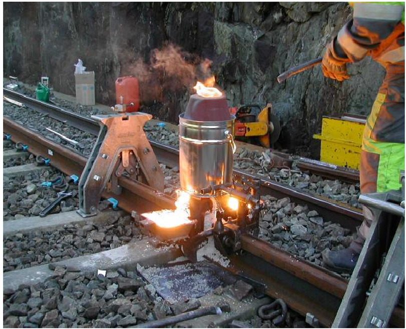 (a) Thermite crucible and mould during the closure-weld pour.
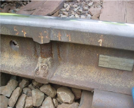 (b) Finished metallurgical weld after trimming and grinding.
Neutralization and related maintenance work must be planned around the neutral-temperature range. In Bane NOR practice this means \(T_n = 21 \pm 3\,^\circ\)C, with additional temperature limits for tamping and lining that depend on curve radius and whether the track position can be controlled against fixed reference marks [6, 81, 78].
9.10 Requirements for CWR Track
Bane NOR technical regulations specify requirements for CWR track covering substructure quality, curve radius, ballast, sleepers, rail profile, fastening, and neutralisation [12, 6]:
-
Substructure: Stable and without frost heave
-
Curve radius: \(R > 300\) m with wooden sleepers; \(R > 250\) m with concrete sleepers; \(R > 190\) m with BNF60 friction sleepers
-
Ballast: Crushed stone, fraction 31.5–63 mm
-
Sleeper spacing: maximum 650 mm in tangent track and curves with \(R \geq 500\) m; maximum 600 mm in curves with \(R < 500\) m; 600 mm for new construction and renewal
-
Rail fastenings: Resilient, with adequate clamping force and torsional resistance
-
Rails: Without visible defects, cracks, or burned holes
-
Insulated joints: Only glued types S (Schmidt) or MT, or friction type Exel
-
Turnouts: Must be welded and neutralised according to the turnout procedure, with special control of switch-rail/stock-rail longitudinal position
-
Track displacement surveying (GVUL): Mandatory for all track renewals and new construction
9.11 Chapter Summary
Thermal force. By removing most rail joints, CWR reduces impact loading, noise and maintenance at joints. The price is that thermal expansion and contraction are restrained over long lengths of rail, producing compressive force in hot weather and tensile force in cold weather. Neutral temperature is therefore one of the most important control parameters in CWR design and maintenance.
Longitudinal resistance. Fastenings, sleepers, ballast and connected structures resist rail creep and thermal movement. In the central track panel, movement is effectively restrained; in expansion zones, rail ends can move and rail gaps may change with temperature. Bridges, turnouts and maintenance activities complicate this behaviour because they introduce local changes in restraint and stiffness.
Buckling risk. High rail temperature creates compressive force, but buckling occurs only when the track does not have enough lateral resistance and alignment stability to resist that force. Small-radius curves, poor ballast shoulders, recent tamping, weak sleepers and geometry defects all reduce the buckling margin. This is why CWR safety is linked not only to rail temperature, but also to track condition and maintenance history.
Destressing. Cutting, welding, tamping, ballast cleaning and other work can change the rail's locked-in stress state or reduce track resistance temporarily. Correct destressing restores the required neutral temperature range, while post-maintenance restrictions and inspections protect the track until resistance has recovered. Maintenance timing is therefore part of CWR safety management, especially in warm weather.
System thinking. Rail stress, fastening resistance, ballast condition, curve radius, bridges, turnouts, expansion devices and operational temperature range all interact. A CWR track with high-quality rail but poor lateral support is unsafe, while a well-supported track with incorrect neutral temperature can still be vulnerable. The engineering goal is to maintain a stable balance between thermal force and track resistance throughout the year.
Assignments
Assignment 1: Rail thermal stress and neutral temperature
A 54E3 rail (\(A = 6948\,\mathrm{mm}^2\)) in a CWR section is laid at a stress-free temperature of \(18\,^\circ\mathrm{C}\) (at the lower limit of a \(21\pm3\,^\circ\mathrm{C}\) tolerance band). The rail temperature rises to \(52\,^\circ\mathrm{C}\) in summer and drops to \(-32\,^\circ\mathrm{C}\) in winter.
(a) Calculate the compressive force in one rail and in both rails at \(52\,^\circ\mathrm{C}\).
(b) Calculate the tensile force in one rail and in both rails at \(-32\,^\circ\)C.
(c) A correctly neutralised rail (\(T_n = 21\,^\circ\)C) in the same temperature range would develop what maximum compressive and tensile forces in both rails?
(d) Which scenario is more critical for summer buckling, and which is more critical for winter fracture?
Assignment 2: CWR tamping in hot weather
A CWR section in a curve of \(R = 350\) m with concrete sleepers is being tamped in midsummer with a rail temperature of \(42\,^\circ\mathrm{C}\). The neutral temperature is \(21\,^\circ\mathrm{C}\). The pre-tamping total LTR for the track panel is 12 kN/m; after tamping, it drops to 40 %. The total compressive force in both rails is 800 kN.
(a) What is the required total LTR per metre using \(q_\mathrm{tot}=P_\mathrm{tot}/R\)?
(b) Does the post-tamping LTR satisfy this requirement?
(c) Why is the rail temperature still operationally critical even if the simple \(q_\mathrm{tot}\) check is satisfied?
(d) What operational measures should be taken immediately?
Assignment 3: CWR destressing calculation
A CWR section is to be destressed in spring. The rail temperature at the time of destressing is \(12\,^\circ\mathrm{C}\), but the target neutral temperature is \(21\,^\circ\mathrm{C}\).
(a) Explain the procedure for achieving the correct neutral temperature by destressing with heaters or by cutting and inserting weld gaps.
(b) If the track is destressed without heating, what will the actual neutral temperature be, and what is the consequence for summer compressive forces?
(c) Bane NOR allows \(T_n = 21 \pm 3\,^\circ\mathrm{C}\) [10]. Does a rail installed at \(18\,^\circ\mathrm{C}\) comply, and why can it still be less favourable for summer buckling than a rail neutralised at \(21\,^\circ\mathrm{C}\)?
Assignment 4: CWR breathing length
The breathing length (ankerlengde) of a CWR section is the zone near a free rail end where longitudinal displacements occur with temperature changes. For one 54E1 rail (\(A = 6{,}934\,\mathrm{mm}^2\), \(E = 210\,\mathrm{GPa}\), \(\alpha = 1.15\times10^{-5}\,\mathrm{K}^{-1}\)) on concrete sleepers with a ballast longitudinal restraint of \(r_\ell = 10\,\mathrm{kN\,m^{-1}}\) per rail:
(a) Derive an expression for the breathing length \(L_e\) in terms of the temperature change \(\Delta T\).
(b) Calculate \(L_e\) for \(\Delta T = 40\,\mathrm{K}\).
(c) If the rail is welded to the next section \(80\,\mathrm{m}\) from a bridge abutment, and the bridge imposes an additional longitudinal force of \(120\,\mathrm{kN}\) per rail, is the \(80\,\mathrm{m}\) section sufficient to absorb the combined longitudinal force?
Assignment 5: CWR buckling check
A CWR track section on a curve of \(R = 400\,\mathrm{m}\) has a rail temperature \(22\,^\circ\mathrm{C}\) above the neutral temperature \(T_n\). The lateral ballast resistance after recent tamping is \(q_\mathrm{rail} = 8\,\mathrm{kN\,m^{-1}}\) per rail. The track uses 60E1 rails (\(A = 7686\,\mathrm{mm}^2\); use the lateral rail inertia \(I_\mathrm{lat} = 512.3\,\mathrm{cm}^4\) per rail for the Meier calculation, not the vertical bending inertia).
(a) Calculate the total axial compressive force \(P_\mathrm{tot}\) in both rails.
(b) Calculate the required total lateral track resistance per metre \(q_{\mathrm{tot,req}}=P_\mathrm{tot}/R\).
(c) Convert the available resistance to the same whole-track convention (\(q_\mathrm{tot}=2q_\mathrm{rail}\)). Does the post-tamping resistance satisfy the simple buckling-resistance requirement?
(d) Using the Meier–Chatkeo method for curved track (Eq. 9.10) with initial misalignment \(f^* = 1.5\,\mathrm{cm}\), \(J = 2 \times 512.3\,\mathrm{cm}^4\), \(F = 2 \times 76.86\,\mathrm{cm}^2\), \(R = 40{,}000\,\mathrm{cm}\), \(k_1 = k_2 = 1\), and \(w = 2q_\mathrm{rail}=160\,\mathrm{N\,cm^{-1}}\), estimate the critical temperature increase \(\Delta t_\mathrm{cr}\). Is the actual temperature increase (22 \(^\circ\)C) within the safe range?
Assignment 6: Longitudinal resistance and rail-gap behaviour
A ballasted track with continuously welded rail of rail type 60E1 has an average longitudinal ballast resistance \(r_\ell = 8\) kN/m per rail. During one hot summer, the rail temperature was measured to be 56 \(^\circ\)C. The neutral temperature of the rail is 21 \(^\circ\)C (Bane NOR technical regulations). Use the following parameters:
-
Cross-sectional area of two 60E1 rails: \(F = 2 \times 76.9\,\mathrm{cm}^2 = 153.8\,\mathrm{cm}^2\)
-
Modulus of elasticity: \(E = 210 \times 10^5\,\mathrm{N\,cm^{-2}}\)
-
Coefficient of thermal expansion: \(\alpha = 1.15 \times 10^{-5}\,\mathrm{K}^{-1}\)
The longitudinal ballast resistance is used only for the breathing-length calculation in part (c); part (b) asks for the required lateral resistance and should not be checked against \(r_\ell\).
(a) Calculate the total axial compressive force \(P_\mathrm{tot}\) in both rails at \(T = 56\,^\circ\)C.
(b) Calculate the minimum required total lateral track resistance per unit length to prevent buckling in a curve of \(R = 500\) m.
(c) At what distance from the free end of the CWR section does one rail reach the locked-zone axial force? (Breathing length for \(\Delta t = 35\,^\circ\)C using \(r_\ell = 8\) kN/m per rail.)