Signal and Interlocking System
11.1 Introduction
The signalling system is the nervous system of the railway. Its primary purpose is to prevent train collisions and derailments while simultaneously maximising line capacity [10, 65]. This chapter covers the main components of a railway signalling system: interlocking, train detection, level-crossing protection, automatic train control (ATC) [10] and the transition to the modern European Rail Traffic Management System (ERTMS) [29].
Railway operation involves vehicles that are heavy, high-speed, and have long braking distances. A train travelling at 200 km/h may require more than 2 km to stop. Drivers cannot see around curves, through tunnels or over hills. Without a system that prevents two trains from occupying the same piece of track simultaneously, collisions would be unavoidable.
The signalling system provides two fundamental guarantees:
-
Safety: at most one train occupies any given section of track at any time, and conflicting movements are physically prevented.
-
Efficiency: capacity is maximised by releasing sections to the next train as soon as the preceding train has cleared them.
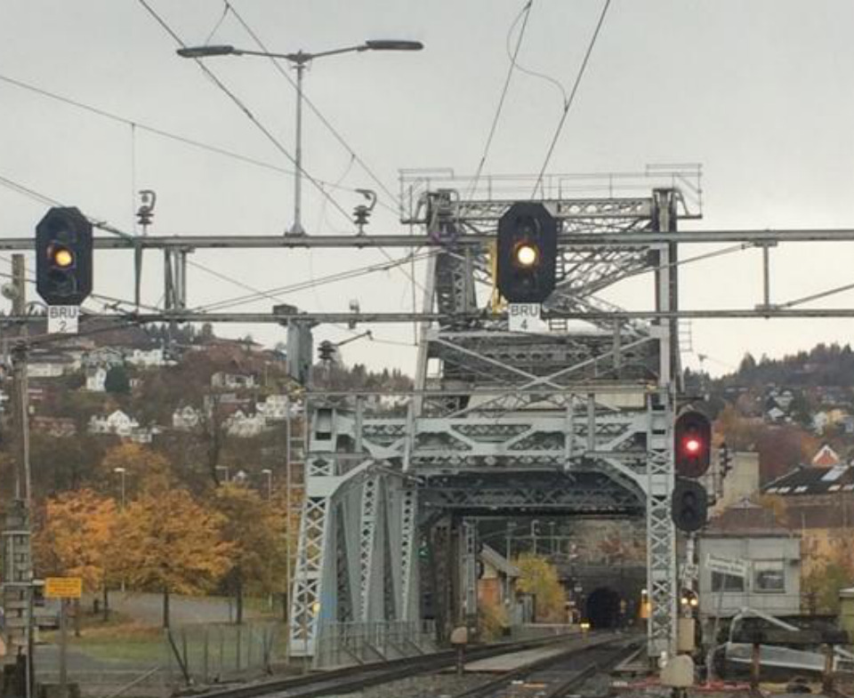
Figure 11.1 shows example lineside signals at Skansen bridge in Trondheim. The photograph is used here as a visual example of installed signalling equipment, not as a complete signalling-layout drawing.
The signalling functions treated in this chapter include:
-
Interlocking: ensures that conflicting routes are never set simultaneously.
-
Level-crossing system: controls road crossings.
-
Centralised Traffic Control (CTC): provides remote supervision and control of the network.
-
Automatic Train Control (ATC): enforces supervised speed and signal information on-board.
-
Additional subsystems: shunting yard control, avalanche detection, tunnel gates, moveable bridge interlocking.
11.2 Interlocking
Interlocking is the safety layer that turns signalling rules into enforceable route logic. It prevents incompatible movements from being authorised at the same time.
11.2.1 Concept
The interlocking is the core safety logic of the signalling system. It is a state machine that enforces dependencies and locking rules between signals, points (switches), and track sections. A train route is a corridor of track, locked and secured for one specific train, from one signal to the next.
The safety logic may be implemented in very different hardware. Relay interlockings realise the route logic with hard-wired contacts and coils; if a relay loses power, its contacts drop to the restrictive state. Electronic interlockings implement the same logic in safety-certified processors connected to signals, points and track circuits through input/output modules. They are more compact and easier to interface with CTC and ERTMS, while relay rooms are physically larger and later changes often require rewiring. Figure 11.2 contrasts these two implementations.
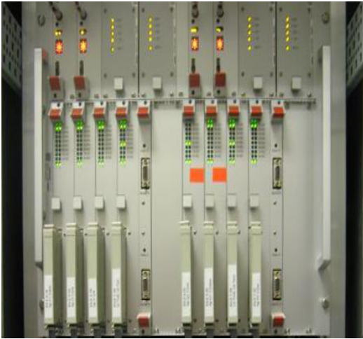 (a) Electronic interlocking cabinet
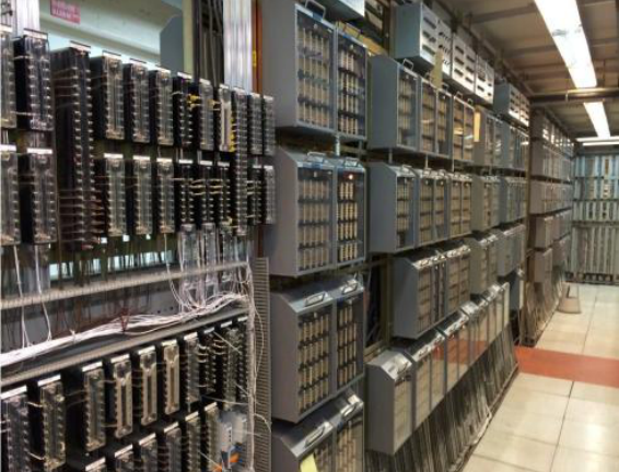 (b) Relay interlocking room
To set a train route, the interlocking must verify that:
-
All track sections within the route are free.
-
All signals conflicting with the route are set to "Stop".
-
The safety zone beyond the end of the route is unoccupied.
-
All points within and immediately beyond the route are correctly positioned and locked.
Only once all conditions are satisfied may the entry signal display a proceed aspect. The route is released and locks are removed only after the train has fully passed through the section, normally with a small release delay.
11.2.2 Technology Generations
Interlocking technology has evolved through three generations:
Mechanical interlocking (pre-1950s).
Levers, rods and cams physically enforced the dependencies. Changing a signal or point position without satisfying prerequisites was mechanically impossible.
Relay-based interlocking (1950s–present).
Electromagnetic relays implement the logic in relay ladder circuits. Approximately 80% of Norwegian interlocking is still relay-based (NSI-63, NSB-77 at Oslo S, NSB-78 on Bergensbanen, NSB-84 on Østfoldbanen, NSB-87 on Rørosbanen) [41]. Relay systems are inherently fail-safe: relay coil failure leaves the contact in the de-energised (safe) position.
Electronic interlocking (1990s–present).
Software logic replaces relay ladders. Norwegian examples include NSB-94/Merkur, Ebilock 850, Ebilock 950, Siemens Simis-C and Thales L90-5 [27]. Computer interlocking offers flexibility and remote diagnostics but requires rigorous formal verification to achieve the same safety integrity as relay systems.
11.2.3 Fail-Safe Principle
The fail-safe principle is fundamental to all railway signalling. A signal may display a proceed aspect only after a long sequence of positive checks; any unresolved condition causes the signal to remain at or revert to "Stop" (red). This is known as a signal failure, though the signalling system itself may not be at fault, the condition may be an occupied track section, a misaligned point or a communication error.
Fail-safe design means that hardware failures, broken wires, failed relays, lost communication, are designed to lead to the most restrictive (safest) signal aspect, not the most permissive.
11.2.4 Optical Signals
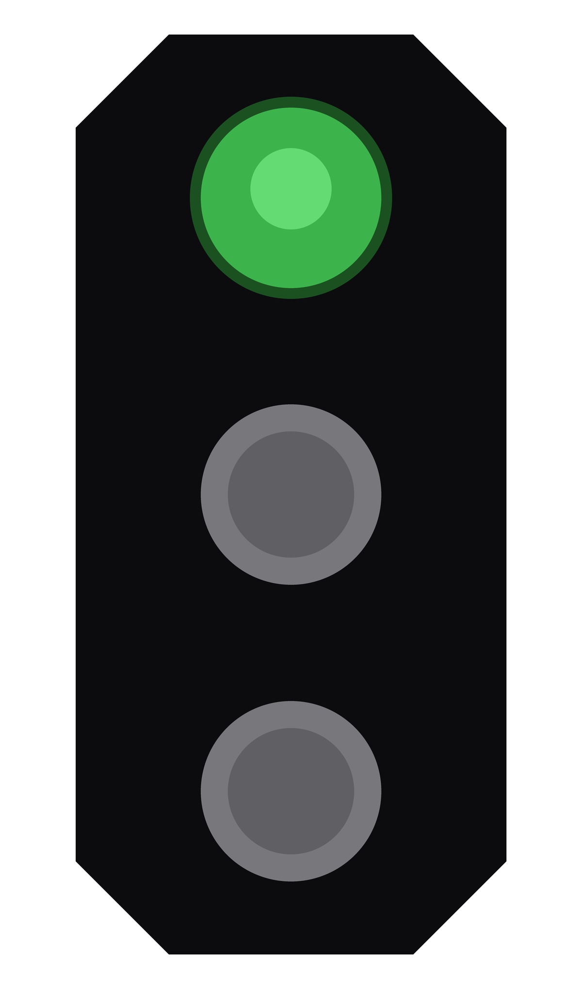
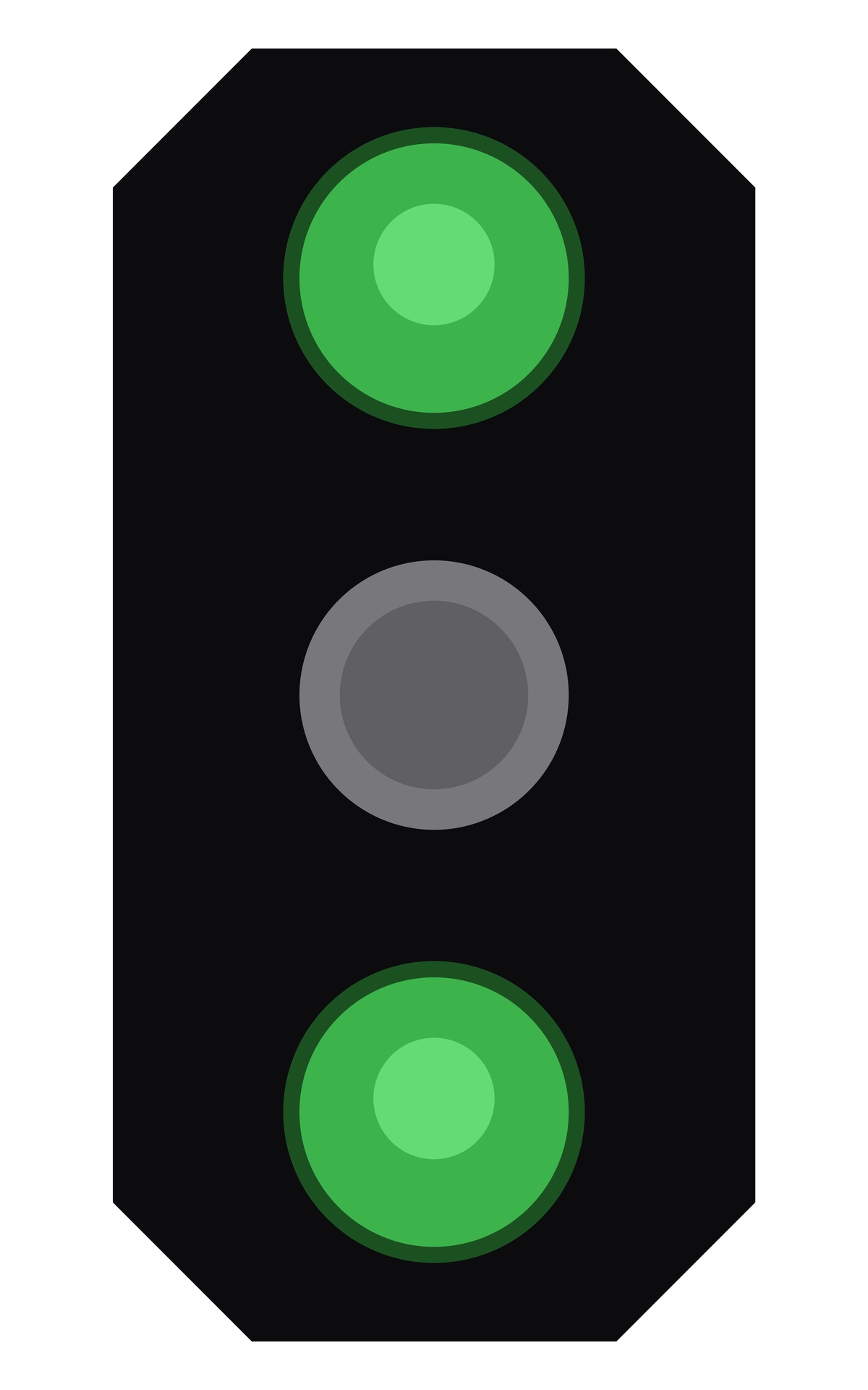
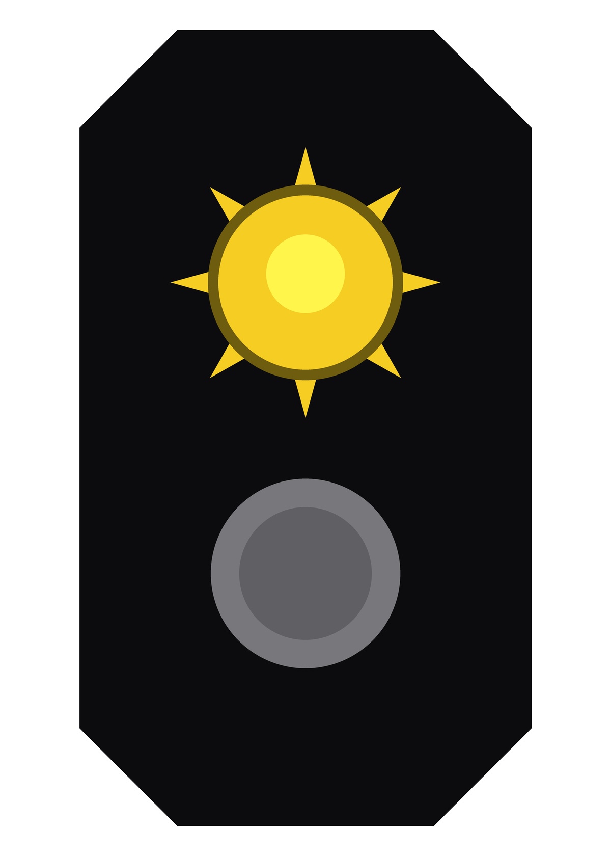
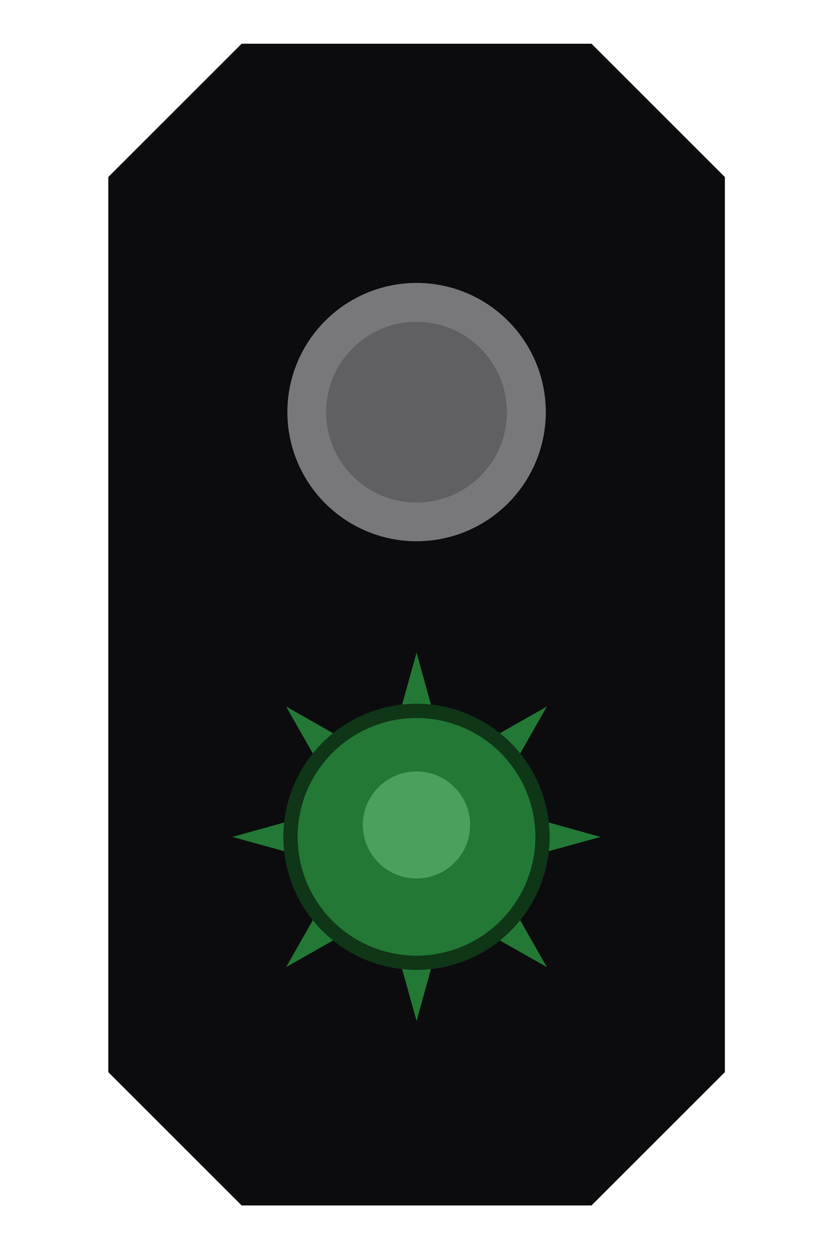
Optical lineside signals in Norway are aspect-based: the meaning depends on the signal type, lamp combination, route indication and local rule context, not on a single colour alone. At an introductory level, the main colours may be read as:
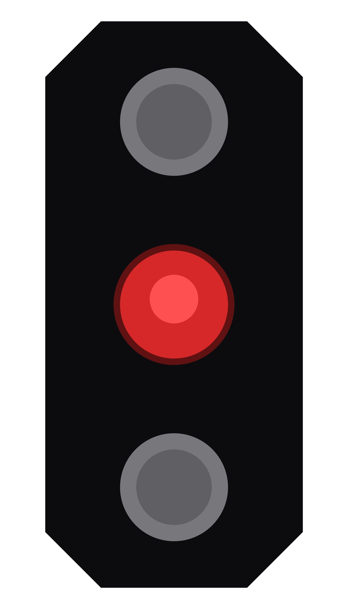
Bane NOR's operational rulebook includes visual examples for the individual signal types. Figure 11.3 reproduces a few common main-signal and distant-signal examples from the rulebook [55].
| Main signals | ||||||||
 |
 |
 |
||||||
| Signal 20B | Signal 21 | Signal 22 | ||||||
| Stop |
|
|
||||||
| Distant signals | ||||||||
 |
 |
 |
||||||
| Signal 23 | Signal 24 | Signal 25 | ||||||
|
|
|
||||||
- Red
-
Stop or no permission to pass the signal.
- Green
-
A proceed aspect; the permitted speed is determined by the full aspect, route and applicable speed information.
- Yellow
-
Restrictive proceed/caution aspect; be prepared for a lower speed or stop at a following signal.
- White
-
Used in shunting and auxiliary signal contexts.
- Purple
-
The associated level-crossing signal shows "Stop in front of level crossing".
The detailed rules must be taken from the current Bane NOR operational rulebook.
11.2.5 ERTMS Level 2 and Marker Boards
On conventional lines, a lineside signal both gives a visual aspect and marks a physical route boundary. ERTMS Level 2 separates these functions. The movement authority, target speed and braking supervision are handled in the cab, while fixed marker boards remain at the trackside as physical reference points for where an authority may start or end. The full ERTMS architecture is treated later in Section 11.8; here the important point is that the marker board is not a colour-light signal. It does not display dynamic speed or proceed information. It marks a location used by the interlocking, the Radio Block Centre and the operational rules.
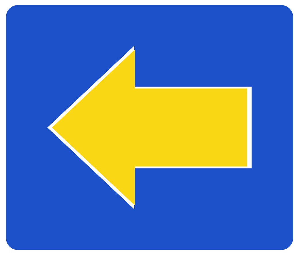
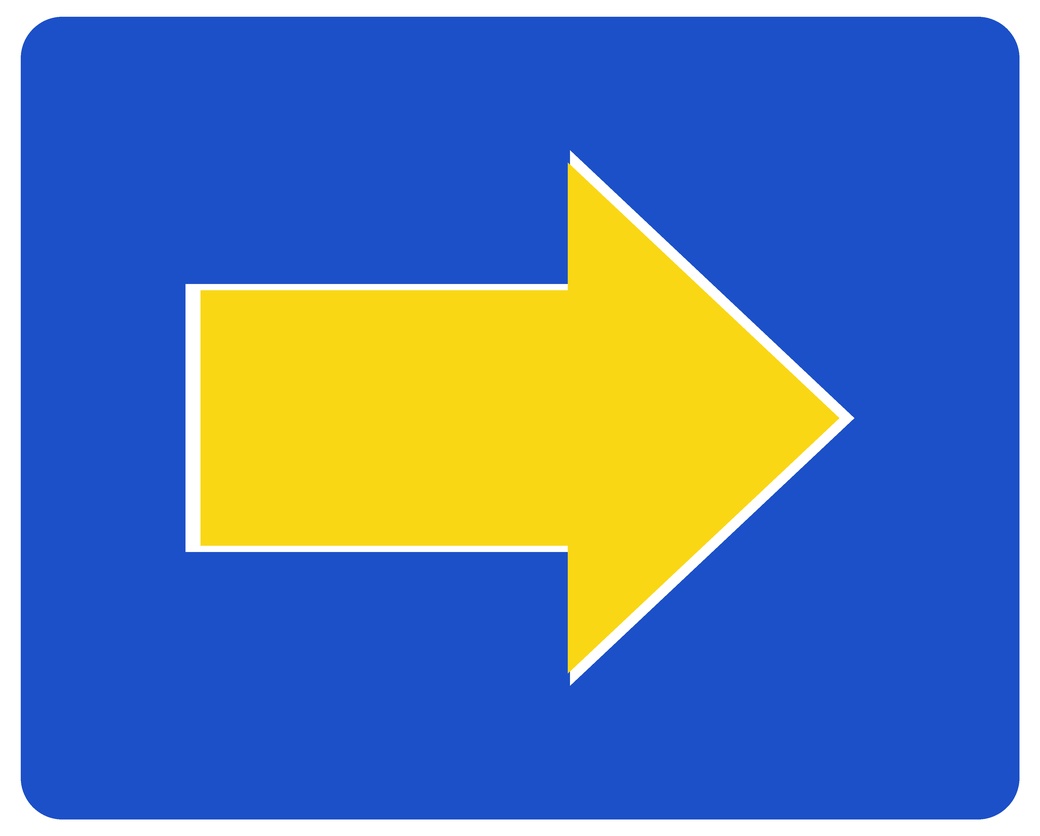
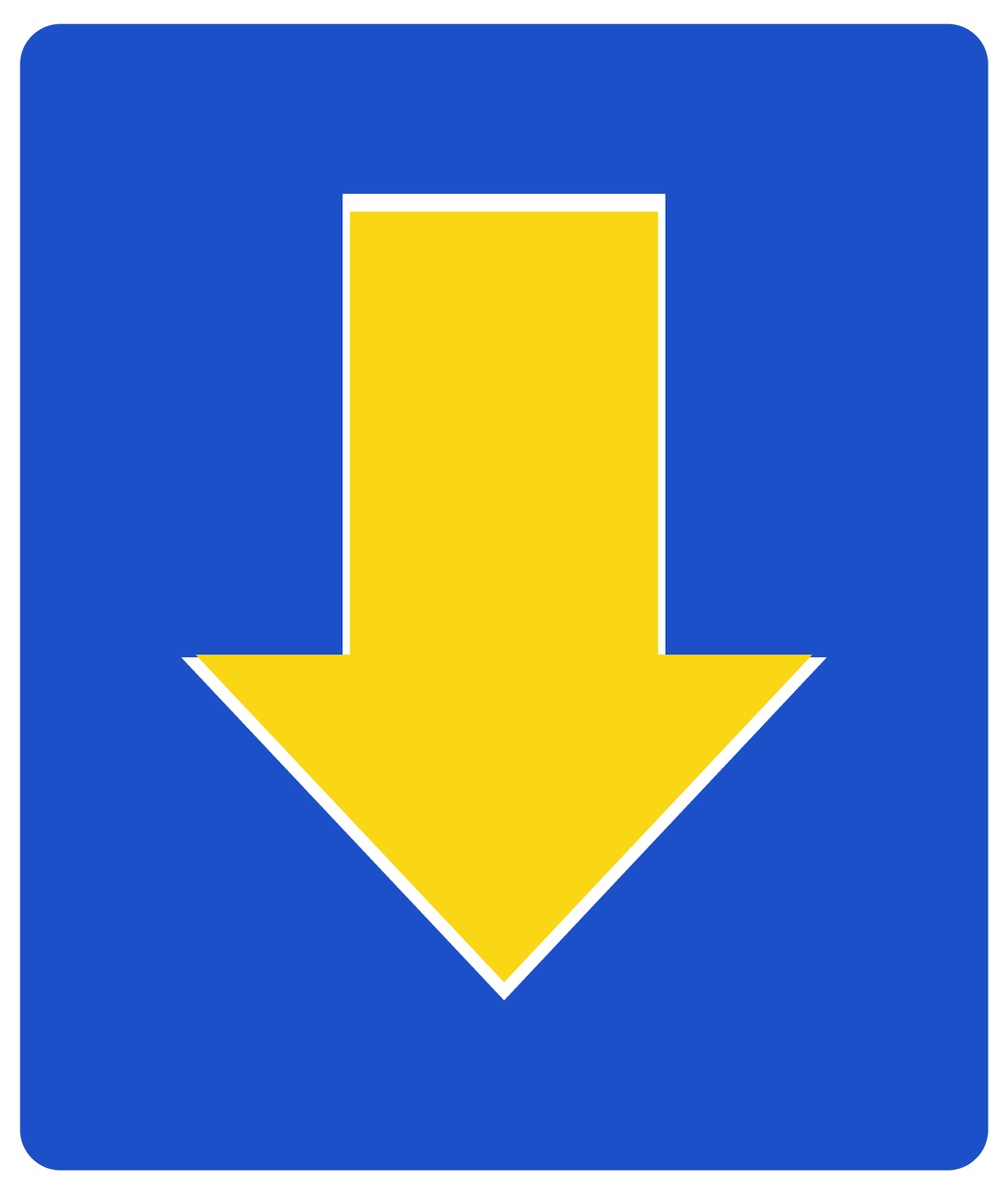
In normal operation, a train may pass an ERTMS stop marker only when the cab display contains a movement authority that permits movement beyond that point. Without such authority, the marker is the physical stop reference. Bane NOR's current rulebook illustrates this with Signal E35 stop markers; the arrow shows which track the marker applies to, as illustrated in Figure 11.4 [54].
 |
 |
 |
| Applies left | Applies right | Applies below |
11.3 Traffic Management and Centralised Traffic Control
Traffic management is the operational layer above the interlocking. The interlocking decides whether a requested route is safe; traffic control decides which route should be requested, for which train, and at what time. It is useful to separate three related terms:
- Local control
-
A signaller or station operator sets routes from a control panel at the station. The station interlocking still proves the route before any signal can clear.
- Remote-controlled station
-
The station has its own interlocking, points, signals and train-detection equipment, but commands and indications are transmitted to a control centre. A local panel (stillerapparat) may remain for maintenance or degraded operation.
- Centralised traffic control (CTC)
-
One dispatcher supervises and controls several remote-controlled stations and line sections from a traffic-control centre. The dispatcher sees the traffic situation, requests routes and handles disturbances, while each local interlocking still performs the safety checks.
Figure 11.5 shows a modern Norwegian traffic-control room, where dispatchers supervise train movements, communicate with operating staff and interact with the centralised control systems from a shared operations floor.
![Traffic-control room used for railway operations in the Oslo area [64].](../../assets/chapters/ch11/original/figures_web/fig_ctc_oslo_control_room_elmagasinet.jpg)
In practice, CTC provides the live traffic picture: train positions, track occupancy, points, signals, locked routes, alarms and conflicts. It also supports remote route setting and functions such as pre-set or time-delayed crossing sequences, where a crossing manoeuvre is prepared in advance and executes when the required track sections and route conditions are available. A Traffic Management System (TMS) adds a planning and regulation layer on top of CTC, using timetable data, train describers and decision support to help dispatchers prioritise trains and recover from disturbances. Norwegian installations have used different generations of such systems, including names such as VICOS, EBICOS and Railmanager; these names are examples of platforms, not the central concept to memorise.
11.4 Level-Crossing Systems
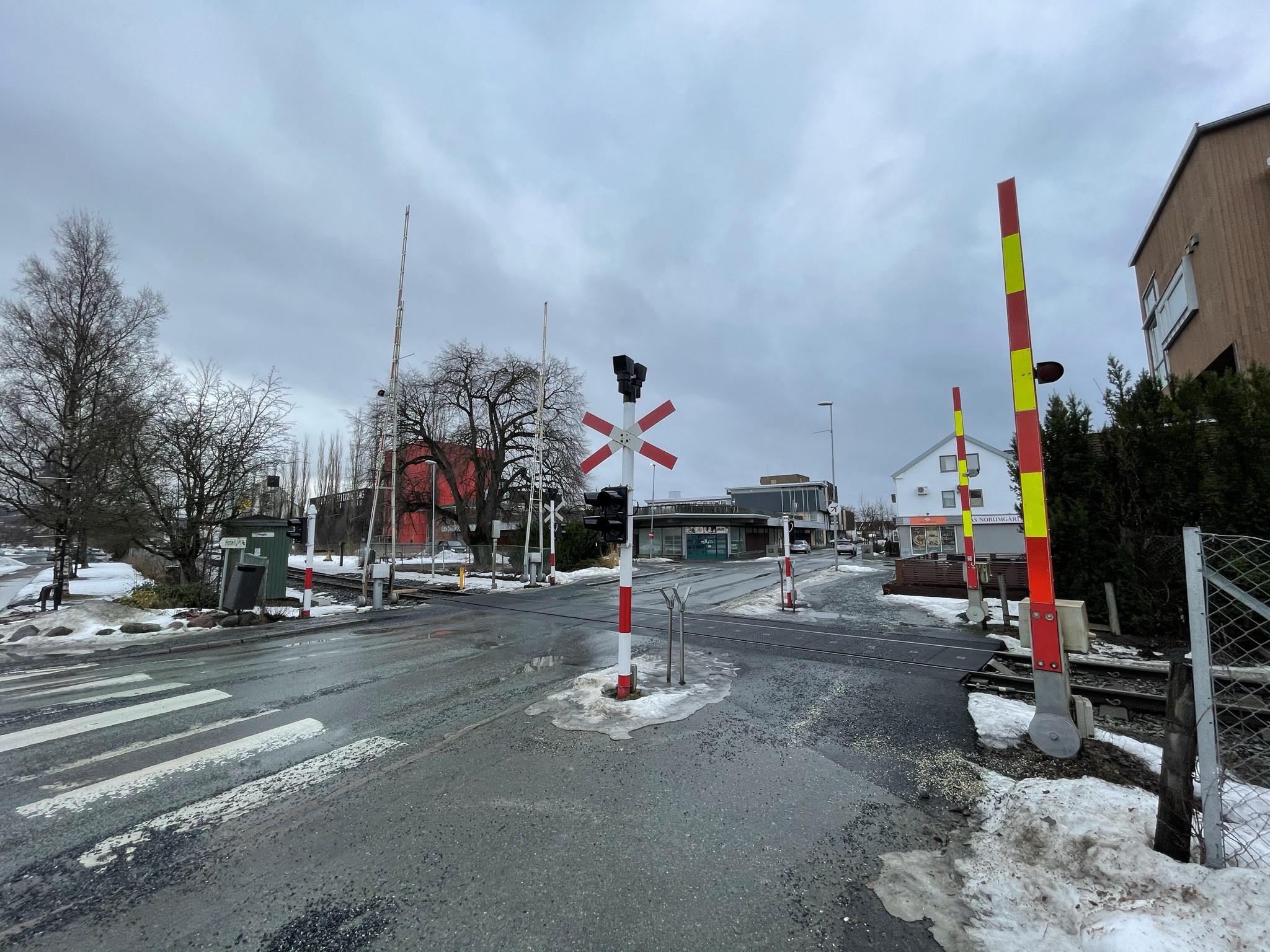
Level crossings are the interface between the railway and the road network, as shown by the protected crossing with lifting barriers and road-signal heads in Figure 11.6. Bane NOR material distinguishes protected crossings such as full-barrier, half-barrier and light/sound installations. At an introductory level, the protection can be grouped by intensity as follows [32]:
- Full barrier
-
Barriers block the entire roadway, supplemented by acoustic warning and road signals. Used on high-traffic roads.
- Half barrier
-
Barriers block only the right lane; vehicles on the left lane cannot enter once a barrier is down. Acoustic warning and road signals.
- Road signal system
-
Acoustic and road signals only; no barrier.
- Warning lamp
-
Minimal protection; typically used for agricultural crossings with very low and predictable usage.
Bane NOR's operational rulebook also defines railway-side level-crossing signals for the driver. The examples in Figure 11.7 show the train-side stop/proceed indications for a protected crossing and the corresponding distant signals.
| Level-crossing signal | Distant signal for level crossing | ||||||||||||||
![Bane NOR examples of railway-side level-crossing signals and distant signals [55].](../../assets/chapters/ch11/original/figures_banenor_signals/planovergang-signal-55-stopp.jpg) |
![Bane NOR examples of railway-side level-crossing signals and distant signals [55].](../../assets/chapters/ch11/original/figures_banenor_signals/planovergang-signal-56-passere.jpg) |
![Bane NOR examples of railway-side level-crossing signals and distant signals [55].](../../assets/chapters/ch11/original/figures_banenor_signals/planovergang-forsignal-57-stopp.jpg) |
|
||||||||||||
|
|
|
|
||||||||||||
The crossing is activated when a train enters the approach zone (Activation point A) and deactivated after the train clears the crossing (Deactivation point A, with equivalent points on the other side of the crossing).
11.5 Train Detection
The interlocking does not need a continuous map of the train; it needs reliable section states. Track is divided into detection sections, and each section is reported as clear or occupied before a route can be set. Figure 11.8 shows this basic principle before the two common detection technologies are introduced.
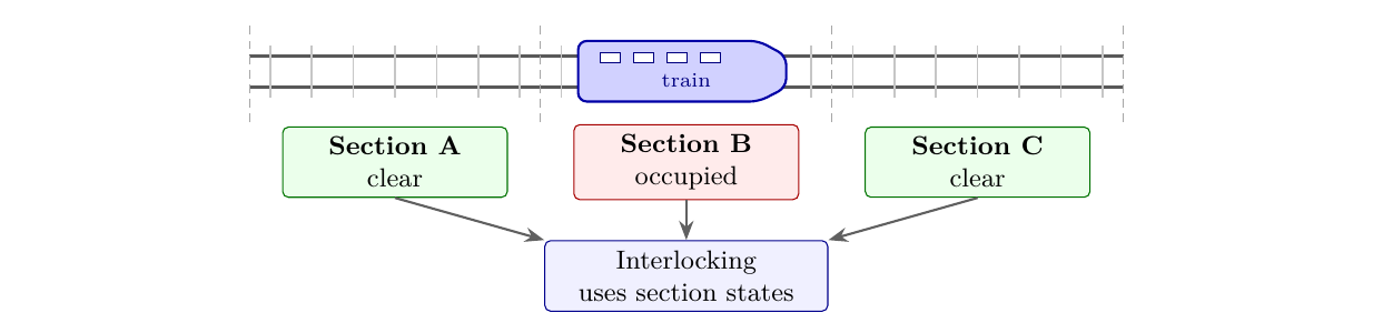
The two most common detection methods in Norway are track circuits and axle counters [10].
11.5.1 Track Circuits
Track circuits were introduced in Chapter 6 as one reason why rail-seat components, fastenings and insulated joints must provide reliable electrical insulation. The same idea is revisited here from the signalling side: the rails carry the detection current, and the interlocking uses the resulting section state as a safety input. Figure 11.9 shows the free and occupied states in the principle drawing.
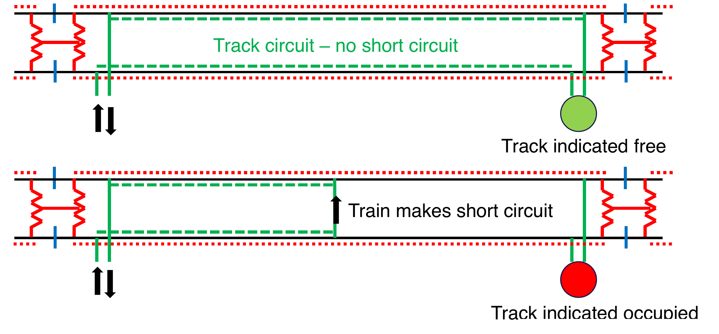
The signalling interpretation is fail-safe: the receiver is energised only for a free section. When train axles shunt the rails, the receiver de-energises and the section is indicated occupied. Loss of the detection current also drives the system toward the restrictive state rather than toward a false "free" indication.
On electrified lines the traction return current uses the rails; the track circuit must use a frequency different from the traction supply frequency (or use coded signals) to discriminate between train-detection current and traction return current. Insulated rail joints electrically separate adjacent track circuit sections.
Limitations of track circuits include sensitivity to rail rust/oxidation (poor electrical contact), contamination (sand, leaves) which may falsely indicate "free", and the need for insulated joints which add a maintenance burden.
11.5.2 Axle Counters
For axle counters, the key safety information is the balance between axles counted into and out of a detection section; Figure 11.10 shows the trackside counting heads, junction boxes, evaluator and control-room output used to form that section state.
![Axle-counter system with trackside counting heads and evaluator [142].](../../assets/chapters/ch11/original/figures_web/fig_axle_counter_railsystem.jpg)
An axle counter detects individual axles by the disturbance they cause in a magnetic field generated across the rail head. Counting heads are installed at both ends of a detection section. The system counts axles entering and leaving:
-
Count \(= 0\): Section clear.
-
Count \(> 0\): Section occupied (axles entered but not yet left).
-
Count returns to 0: Section clear again.
The tuner unit powers the counting head, determines train direction and transmits axle counts to the interlocking. Axle counters do not require insulated rail joints and are less sensitive to rail contamination [141]. However, they can be affected by snow accumulation and require a reset procedure after maintenance work on the track.
A road-rail vehicle entering the track section must be registered as occupying the section to prevent a false "free" indication. Similarly, a kicksled or pedestrian crossing at rail height would not be detected by a track circuit but would also not be detected by an axle counter, underlining that neither system detects people on the track.
11.6 Point Machines and Flank Protection
A point machine (switch machine) is the electromechanical actuator that moves the switch blades of a set of points and provides a locked, detected position to the interlocking. For signalling, the important information is not the physical machine type but whether the point has reached and locked in the commanded position before a route depending on it can be cleared. The switch blades, stock rails and crossing components controlled by the point machine are described as track components in Chapter 14.
Figure 11.11 shows two point-machine examples: a conventional open-drive unit and a sleeper-mounted unit.
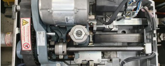 (a) Conventional open-drive unit
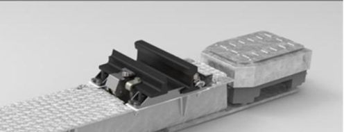 (b) Sleeper-mounted unit
Flank protection prevents runaway vehicles from entering an occupied or secured train route from a siding. Two devices are used:
-
Derailer: a simple device placed on the rail that forces any approaching vehicle off the track before it can enter the protected area. Figure 11.12 shows a rail-mounted example. Approved only for speeds up to 40 km/h.
-
Catch point: a derailing switch (avsporingsveksel) that diverts a runaway vehicle away from the protected route. It is more effective than a simple derailer, but requires more space [19].
![Rail-mounted derailer on a siding [120].](../../assets/chapters/ch11/original/figures_web/fig_derailer_wikimedia.jpg)
11.7 Automatic Train Control
Automatic Train Control adds onboard supervision to the lineside signalling system. Its purpose is to reduce the consequences of missed signals or overspeed events.
11.7.1 Principles
Even with a perfectly functioning signal system and a red signal displayed, consequences depend on whether the driver sees and obeys the signal. Automatic Train Protection (ATP) is the safety function that supervises whether the train remains within its permitted speed and movement authority, and intervenes by braking if necessary. In Norway this protection function is provided by Automatic Train Control (ATC), the on-board system that supervises driver compliance with signal and speed information.
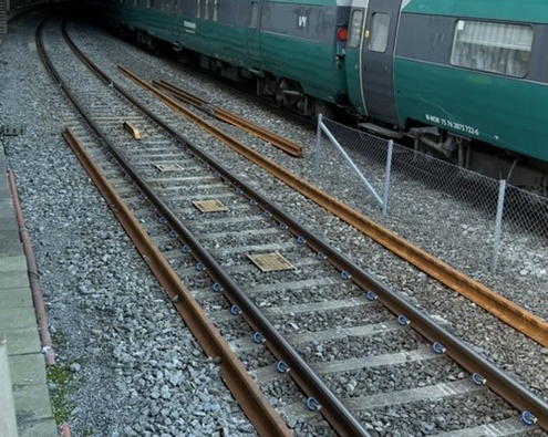
The Norwegian ATC system operates with lineside balises (radio transponders embedded in the sleepers between the rails). When a train passes over a balise, a magnetic field from the train's on-board antenna activates the balise, which transmits encoded data to the on-board computer. Figure 11.13 shows balises mounted between the running rails in a station track. The transmitted data includes:
-
Speed limits and signal aspects ahead.
-
Signal-related permission or restriction information for the equipped point.
-
Gradient information for brake curve calculation.
This information is presented on the cab display. In ETCS/ERTMS terminology, this driver's cab display is the Driver Machine Interface (DMI): the screen that shows speed, target distance, permitted speed, operating mode and profile information to the driver. Figure 11.14 shows an example of the DMI layout.
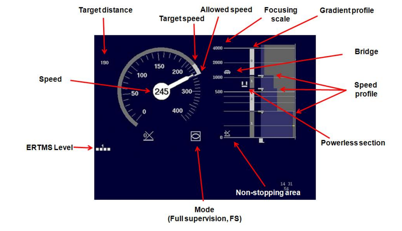
The on-board system supervises compliance. If the driver fails to take action (reduce speed, acknowledge a restrictive aspect), the ATC system applies the brakes automatically.
11.7.2 ATC Coverage Levels
ATC coverage levels differ mainly by where balises are installed and how completely signal information and speed restrictions are supervised. Table 11.1 summarises the progression from no on-board intervention to intermittent national ATC supervision, full national ATC supervision and cab-based ERTMS supervision.
| Coverage level | Trackside equipment | Main supervision effect |
|---|---|---|
| Non-equipped | No ATC balises for train protection | No automatic train-protection supervision; safety depends on operating rules, signalling rules and driver compliance. |
| DATC, partly equipped | Balises at main signals and selected control points | Supervises main-signal information and important restrictions, but not every intermediate speed sign. |
| FATC, fully equipped | Balises at signals and speed boards | Supervises both signal aspects and permissible speeds over the equipped line section. |
| ERTMS Level 2 | Balises for position reference plus radio movement authority from the RBC | Cab signalling and continuous brake-curve supervision replace traditional optical signal dependence. |
11.8 ERTMS: European Rail Traffic Management System
ERTMS is introduced here as both a technical renewal programme and an interoperability standard. The need for it follows from the age and fragmentation of legacy signalling systems.
11.8.1 Background
ERTMS is driven by renewal pressure from legacy signalling assets. Norway's legacy signalling systems face a systemic problem:
-
Most systems were installed in the 1970s–1990s and have exceeded their design lifetimes.
-
Spare parts for older relay systems are no longer manufactured.
-
Supplier support has ended for several system types.
-
The technology is no longer taught, so specialist maintenance knowledge is disappearing.
-
The result is increasing fault frequency and fault-correction times, leading to reduced availability and capacity.
A comprehensive renewal of the entire Norwegian signalling infrastructure is therefore necessary [29]. Bane NOR has chosen ERTMS Level 2 as the national standard for this renewal [10].
11.8.2 ERTMS Architecture
ERTMS (European Rail Traffic Management System) consists of three components:
-
ETCS (European Train Control System): the standardised train protection and control subsystem, covering cab signalling, speed supervision, and movement authorities.
-
GSM-R (Global System for Mobile communications, Railway): the dedicated digital radio network used for voice communication and data transmission between trains and the Radio Block Centre (RBC). GSM-R is being phased out across Europe and will be replaced by FRMCS (Future Railway Mobile Communication System), a 5G-based standard developed by the European Union Agency for Railways (ERA). FRMCS offers significantly higher bandwidth, lower latency, and supports modern cybersecurity requirements. The transition is planned for completion across European networks by approximately 2035; Norway's ERTMS rollout plan accounts for this migration.
-
Operational regulations: harmonised rules that allow trains from any ERTMS-equipped country to operate on any ERTMS-equipped line.
The principal ETCS levels are summarised in Table 11.2. This is a conceptual overview of how movement authority and train supervision change from conventional signalling toward cab signalling and moving-block operation.
| Level | Authority path | Lineside signals | Train detection and integrity |
|---|---|---|---|
| Level 0 | Conventional signalling only | Required | No ETCS supervision; the train follows national lineside signalling and national protection systems if fitted. |
| Level 1 | Signal \(\rightarrow\) Eurobalise \(\rightarrow\) cab | Normally retained | Trackside systems prove train location and train completeness. |
| Level 2 | RBC \(\xrightarrow{\text{radio}}\) cab; balises correct position | Optional; authority is shown on the DMI | Trackside train detection remains part of the authority calculation. |
| Level 3 concept | RBC \(\xrightarrow{\text{radio}}\) cab + train integrity report | Not needed for movement authority | The train reports its own integrity, enabling moving-block operation. |
ERTMS changes both the driver's information source and the way movement authority is enforced, especially when moving from lineside signals to continuous radio supervision.
The Norwegian rollout should be understood separately from the general level definitions in Table 11.2. Bane NOR has selected ERTMS Level 2 as the national standard for the renewal programme [10], and Norway plans to install ERTMS Level 2 on the entire national railway network [92]. Gjøvikbanen nord and Østfoldbanens Østre linje are the first lines in revenue operation with the new system. The Level 3 row is therefore included as a theoretical moving-block/train-integrity concept, not as a separate Norwegian rollout target.
11.9 Simultaneous Entry and Safety Distances
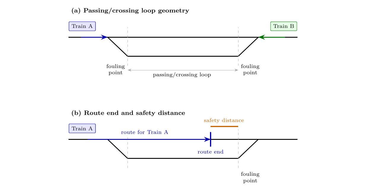
On a single-track railway, opposing trains can meet only at locations with more than one usable track. A passing/crossing loop (kryssingsspor) is a short double-track section inserted into a single-track line so that two trains travelling in opposite directions can enter the station, pass each other, and then continue onto the single track again. Its capacity is governed not only by the physical length of the loop, but also by what the interlocking must reserve beyond each authorised route. If two opposing trains cannot enter the loop at the same time, one train must wait outside the station until the other train has arrived and the route has been released. That waiting time consumes timetable margin and reduces the number of trains that can be planned through the line. Figure 11.15 introduces the basic track-layout terms used in this explanation; trains A and B are opposing trains approaching the loop from different ends. A fouling point is the clearance limit near a turnout: beyond it, a vehicle would obstruct the converging track.
11.9.1 Route-End Protection
At the end of every secured train route there is a safety distance: a protected zone that must remain free of conflicting activity. The required distance is a layout- and system-specific design parameter, affected by release speed, braking supervision, overlap philosophy, train detection, route locking and local Bane NOR rules. The release speed is the maximum speed the train is permitted to have when approaching the end of its route. The values in Table 11.3 are sample values used to explain the simultaneous-entry calculation, not universal constants.
For the simplified capacity check used here, compare the distance available from the route-ending object (signal or marker board) to the nearest fouling point with the required safety distance:
If the inequality is satisfied at both ends of the loop, the protected zones can stop before the fouling points and simultaneous entry is geometrically possible. If the required safety distance is longer than the available distance, the protected zone passes the fouling point and the opposite entry route cannot be set at the same time. The useful design margin is \(d_{\text{available}}-d_{\text{safety}}\).
| System | Protection assumption used here | Operational effect at a passing loop |
|---|---|---|
| Legacy interlocking | Lineside signal and overlap; sample 40 km/h release speed and 250 m safety distance. | Long envelopes can overlap around the fouling point. The interlocking may permit only one entry route, so the other train waits outside the station. |
| ERTMS Level 2 | Marker board and cab authority; sample 20 km/h release speed and 70 m safety distance. | Shorter supervised envelopes can fit before the fouling points. Both entry routes can be clear at once. |
Worked example: checking simultaneous entry.
Assume that a candidate route-ending marker board is 95 m before the fouling point at one end of a passing loop. With the sample ERTMS Level 2 safety distance of 70 m, the margin is
The margin is positive, so the protected zone can stop before the fouling point at this end. If the same layout were checked with the sample legacy safety distance of 250 m, the margin would be
The negative margin means that the protected zone would pass the fouling point, so the opposite entry route could not be set at the same time. For a complete station check, the same calculation must be satisfied at both ends of the loop.
11.9.2 Capacity Consequence at a Passing Loop
Simultaneous entry means that the interlocking can set two opposing train routes at the same time, so that two trains can enter the same crossing station simultaneously rather than one waiting for the other. The mechanism is shown in Figure 11.16. In the legacy case, the two route-end protection envelopes overlap near the centre of the loop. Each route may be safe on its own, but the interlocking cannot prove that both are safe together. In the ERTMS case, the shorter supervised envelopes stop before the fouling points, so the two routes can coexist.
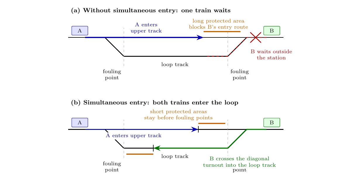
The shorter design distance in the ERTMS sample arises from supervised braking and release-speed enforcement. The ETCS onboard unit estimates train position from odometry and corrects it at balises, while Level 2 operation still relies on trackside train detection and fixed interlocking logic. Simultaneous entry is therefore a combined property of the marker-board layout, movement authority, release speed, route locking and train-detection design, rather than simply "knowing the exact train position".
11.9.3 Paired Marker Boards
The practical ERTMS solution is not only to shorten the protected envelope, but also to choose where the marker boards are placed. With a legacy 250 m safety distance, achieving simultaneous entry often requires either a very long station platform or a trap point that would derail a runaway vehicle before it reaches the fouling point. Figure 11.17 shows the ERTMS principle as a route-ending choice for one arriving train. If an opposing train must enter at the same time, the interlocking chooses the short route ending. If there is no opposing entry route, it can choose the longer route ending and give the arriving train more usable track.
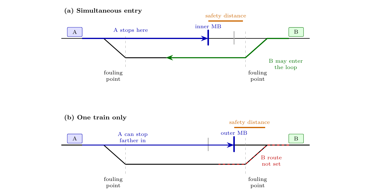
The paired boards are therefore not used at the same time. They are two possible movement-authority end points for the same arriving train, and the interlocking selects only one of them for a given movement; the selected board is shown in blue and the unused board in grey. In Figure 11.17a, the inner marker keeps the safety distance before the fouling point so train B may enter the loop at the same time. In Figure 11.17b, the outer marker gives train A more stopping length, but the opposite route is then not set.
11.10 Condition-Based Maintenance of Signalling
Modern signalling components increasingly incorporate sensors that record operational data continuously. Point machines can log force-versus-travel curves for each operation; deviations from the normal signature indicate a developing fault before it causes a signal failure. Track circuits generate voltage and current data that reveal degrading insulated joints or rail contamination.
By combining these data streams with machine-learning algorithms (Bane NOR has cooperated with Microsoft on such systems), the maintenance philosophy can transition from time-based (replace every \(n\) years) to condition-based (replace when the degradation trend predicts imminent failure) and ultimately to predictive maintenance (replace before the fault propagates to a service disruption). This approach reduces both maintenance costs and the frequency of operationally disruptive signal failures.
11.11 Chapter Summary
Movement authority. Trains cannot stop within sight distance like road vehicles, so train movement must be controlled by signals, movement authorities, route locking and train detection. The signalling system must prevent conflicting movements while still releasing capacity as soon as it is safe to do so. Safety and efficiency are therefore handled by the same technical system.
Interlocking. The interlocking verifies that track sections are free, points are correctly positioned and locked, conflicting signals are at stop, and the required safety zone beyond the route is protected. Only then can a signal display a proceed aspect or a movement authority be issued. Mechanical, relay-based and electronic interlockings implement this logic differently, but the fail-safe principle is the same: uncertainty must lead to the safe state.
Train detection. Track circuits detect trains by electrical shunting of the rails, while axle counters count axles entering and leaving a section. Each method has advantages and limitations: track circuits require insulated rail joints and are sensitive to poor electrical contact, while axle counters require reset procedures and do not inherently detect vehicles that bypass the counting logic. Detection quality is therefore central to both safety and availability.
Protection distances. Braking distance, overlap, safety distance, route release, simultaneous entry and flank protection determine both safety and station capacity. Long safety distances can reduce usable platform or loop length. At passing loops, simultaneous entry preserves capacity by allowing opposing trains to enter together.
ERTMS. Norway's transition to ERTMS responds to ageing legacy equipment, spare-part shortages, declining specialist knowledge and the need for standardised train control. ERTMS changes how movement authority is transmitted and supervised, especially at Level 2 where cab signalling and radio communication replace conventional lineside signals. The change is technical, operational and organisational at the same time.
Assignments
Assignment 1: Fail-safe principle and interlocking
The interlocking must guarantee that conflicting routes are never simultaneously set. Answer the following questions about the fail-safe principle:
(a) If a signal lamp fails, which signal aspect should be displayed, and why is that the fail-safe output?
(b) If a track circuit detects a broken rail or a failed receiver, should the section be reported as occupied or free? Explain why this is the safer output.
(c) For a set of points, what is meant by the normal position? What should happen if the point machine loses power during route setting?
(d) Use the route-setting rule from the chapter: a signal may clear only when the track is clear, the required points are proven, and no conflicting route is set. Complete the table by writing whether the signal may clear in each case. Here, points proven means that the points are locked and detected in the required position.
| Case | Track clear? | Points proven? | No conflict? | May signal clear? |
|---|---|---|---|---|
| All required checks true | yes | yes | yes | |
| Train detected in the route | no | yes | yes | |
| Point position not proven | yes | no | yes | |
| Conflicting route already set | yes | yes | no |
For each "no" case, explain briefly why clearing the signal would be unsafe.
Assignment 2: ERTMS safety distance and simultaneous entry
At a passing loop (a short double-track section on a single-track main line), the usable track length is 750 m. The fouling point at each end of the loop is located 120 m from the nearest possible marker board (or signal) position (i.e. the available distance from the marker board position to the fouling point is 120 m at each end). Use the route-end check and worked example from Section 11.9.1: compare \(d_{\text{available}}\) with \(d_{\text{safety}}\), and calculate the margin \(d_{\text{available}}-d_{\text{safety}}\).
(a) For the sample legacy case, use \(d_{\text{safety}}=250\,\mathrm{m}\). Is simultaneous entry geometrically possible with this station layout? Show the margin and state why or why not.
(b) For the sample ERTMS Level 2 case, use \(d_{\text{safety}}=70\,\mathrm{m}\). Is simultaneous entry geometrically possible? Show the margin and state why or why not.
(c) Based on the two margins, explain qualitatively why the shorter supervised safety distance in the ERTMS sample enables simultaneous entry at stations where legacy signalling cannot, and why this is especially important on a single-track line with high traffic.
Assignment 3: ERTMS levels and lineside signals
Compare ETCS Level 1, Level 2, and Level 3 with respect to: (i) whether lineside signals are required; (ii) how movement authorities are transmitted to the train; (iii) how train position/integrity is determined; and (iv) which level is being deployed on the Norwegian national network and why. Present your comparison as a table with one row for each ETCS level and columns for the four comparison points.