Overbygning
En valgfri KI-generert oversikt. Det skriftlige kapitlet er den autoritative kilden.
2.1 Innledning
Sporets overbygning er sporkonstruksjonen som ligger over formasjonsplanet. Den består av skinner, skinneskjøter og sveiser, befestigelsessystemer (inkludert isolatorer og mellomlegg), sviller og ballast. Sporveksler og sporkryss, samt ballastfrie sporkonstruksjoner, inngår også i overbygningen.
Det grunnleggende prinsippet i Bane NORs tekniske regelverk er at «alle komponenter som benyttes i sporet, skal kunne motstå belastningene de utsettes for som følge av trafikk eller andre påvirkninger.» [10]
Ballast behandles separat i kapittel 3, fordi spesifikasjon, kvalitetskrav og vedlikehold av ballast utgjør et eget jernbaneteknisk fagområde. Dette kapitlet omhandler skinner, befestigelsessystemer, sviller og ballastfritt spor [68, 130, 148].
2.2 Funksjonskrav
Sporets overbygning skal oppfylle flere funksjonskrav samtidig [68, 10]:
Lastoverføring.
Hovedoppgaven er å ta opp krefter fra trafikken og overføre dem til underbygningen uten at verken komponentene i overbygningen eller formasjonsplanet skades.
Kontrollert stivhet og elastisitet.
Overbygningens stivhet har stor innvirkning på utmattingslevetiden til alle komponentene og på kjørekomforten. For høy stivhet konsentrerer belastningen, mens for lav stivhet gir store nedbøyninger og fremskynder forringelse av sporgeometrien.
Slitasjemotstand.
God slitasjemotstand krever omhyggelig materialvalg. Skinneslitasjen avhenger av skinnekvaliteten, geometrien til skinne- og hjulprofilet og friksjonsforholdene i hjul–skinne-kontakten.
Opptak av temperaturkrefter.
Temperaturvariasjoner gir aksialspenninger i skinnene. Disse spenningene stiller krav til utformingen av befestigelser, sviller og ballastskuldre for å hindre sideveis utknekking (solslyng) ved høye temperaturer og skinnebrudd ved lave temperaturer.
Elektrisk isolasjon.
Der sporfelt brukes til togdeteksjon, ledes elektrisk strøm gjennom skinnene og kortsluttes av det rullende materiellet. Komponenter som er i kontakt med skinnen, skal gi tilstrekkelig elektrisk isolasjon til å hindre lekkstrøm gjennom sviller, befestigelser eller ballast som kan svekke signalanleggets funksjon.
Enkel montering og utskifting av komponenter.
Sportilgang er kostbar. Alle komponenter skal derfor være utformet for rask montering og effektiv utskifting.
Økonomi.
Livsløpskostnaden omfatter materialkostnader, komponentenes levetid, arbeidsinnsats, maskintilgang og kostnaden ved trafikkforstyrrelser som skyldes feil.
2.3 Lasttyper som virker på overbygningen
Overbygningen skal motstå påvirkninger i tre hovedretninger: vertikale krefter fra kjøretøyenes tyngde, langsgående krefter fra temperatur, trekkraft og bremsing samt tverrkrefter fra kurvekjøring og stabilitetsvirkninger.
2.3.1 Vertikale laster
Vertikal belastning deles vanligvis inn etter opprinnelse, fordi de ulike lasttypene påvirker dimensjoneringskontroller og vedlikeholdsrelatert nedbrytning på forskjellige måter.
-
Statiske laster skyldes kjøretøyets egenvekt fordelt på akslene.
-
Kvasistatiske laster skyldes sentrifugalkraft i kurver og manglende overhøyde eller overskuddshøyde, som gir lastomlagring mellom de to skinnene under en aksel.
-
Dynamiske laster (støtlaster) skyldes ujevnheter på skinnen (hjulslag, rifler og bølger, ujevne skjøter) eller på hjulets løpeflate. Ved lokale ujevnheter kan dynamiske laster bli opptil \(2{,}5\) ganger den statiske aksellasten.
2.3.2 Langsgående laster
Langsgående påvirkninger virker langs skinnen og overføres gjennom befestigelsessystemet, svillene og ballastens motstand.
-
Temperaturlaster: Høye temperaturer gir trykkspenning i skinnen og fare for sideveis utknekking (solslyng), mens lave temperaturer gir strekkspenning og fare for skinnebrudd.
-
Trekk- og bremsekrefter overføres gjennom befestigelsessystemet til sviller og ballast.
2.3.3 Tverrkrefter
Sidekrefter oppstår i hjul–skinne-kontakten i kurver, ved hunting-bevegelse (ustabile sideveis svingninger) og ved temperaturutvidelse i helsveist spor. Kreftene tas hovedsakelig opp av ballastskulderen (eller av platen i et ballastfritt spor).
2.4 Overbygningsklasser
Bane NOR definerer overbygningsklasser som angir største tillatte aksellast og hastighet for ulike kjøretøykategorier [32]. Klassen er en av de viktigste faktorene som bestemmer hvilken trafikk som kan framføres på en strekning. Tabell 2.1 gjengir verdiene som er publisert i Bane NORs Operativt regelverk, SJN 2.18.1, oppdatert 15. august 2025 [32].
| Klasse | Personvogner | Motorvognsett (EMU/DMU) | ||
|---|---|---|---|---|
| Aksellast [t] | v [km/h] | Aksellast [t] | v [km/h] | |
| a | 16 | 90 | 16 | 90 |
| b | 18 | 100 | 18 | 100 |
| c | 18 | 160 | 20,5/18 | 130/160 |
| c+ | 18 | 160 | 20,5 | 160 |
| d | 18 | 230 | 20,5/20/18/17 | 160/200/250/300 |
| Ofotbanen | 18 | 130 | 20,5 | 130 |
| Klasse | Gods- og arbeidskjøretøy | ||
|---|---|---|---|
| Aksellast [t] | v [km/h] | vboggi [km/h] | |
| a | 22,5/16,5 | 30/70 | 30/70 |
| b | 22,5/20,5/18 | 30/70/80 | 30/70/80 |
| c | 22,5/20,5/18 | 80/90/100 | 90/100/110 |
| c+ | 241/22,5/20,5/18 | 50/90/100/110 | 50/100/110/120 |
| d | 25/22,5/18 | 70/100/110 | 70/120/120 |
| Ofotbanen | 31/22,5 | 50/702 | 50/70 |
Verdier atskilt med skråstrek hører sammen etter plassering: Den første aksellasten leses sammen med den første hastigheten, den andre med den andre, og så videre. For gods- og arbeidskjøretøy er \(v_\mathrm{boggi}\) største hastighet for boggikjøretøy godkjent etter EN 14363 [90]. På Ofotbanen har dagens malmtrafikk normalt en aksellast på 30 t. Verdien 31 t er en øvre grense knyttet til infrastrukturen og særregler, ikke en generell driftstillatelse. Bruken forutsetter fortsatt godkjenning av strekning, kjøretøy og regelverk. 1Verdien 24 t gjelder bare på Nordlandsbanen mellom Guldsmedvik (km 499,517) og Ørtfjell (km 534,630). 2Største hastighet for tomme malmvogner er 60 km/h. Tabellverdiene er infrastrukturens øvre grenser, ikke skiltet hastighet på en bestemt strekning. Lokomotiver i persontog er begrenset til 22,5 t aksellast.
De følgende avsnittene beskriver de standardiserte sporkonstruksjonene som benyttes for klasse c, klasse d og den særskilte belastningen på Ofotbanen.
2.5 Skinner
Skinnene behandles først fordi de både utgjør løpeflaten og er hovedbjelken som fordeler hjullastene til resten av overbygningen.
2.5.1 Funksjon og dimensjoneringsparametere
Skinnene er det primære lastbærende elementet i overbygningen [85, 62]. Følgende dimensjoneringsparametere er avgjørende for valg av skinne:
-
Kontakttrykk og slitasje: Den høye Hertz-kontaktspenningen krever et stål med tilstrekkelig hardhet og slitasjemotstand.
-
Bøyemotstand: Et stort vertikalt arealtreghetsmoment \(I_y\) fordeler lasten over flere sviller og begrenser nedbøyningen.
-
Motstand mot temperaturutknekking: Et stort horisontalt arealtreghetsmoment \(I_z\) øker motstanden mot sideveis utknekking ved trykkspenning fra temperatur.
-
Seighet ved lav temperatur: Skinnestålet skal ikke få sprøbrudd ved laveste dimensjonerende temperatur (vanligvis \(-40\,^\circ\mathrm{C}\) i Norge).
-
Motstand mot utmatting og støt: Syklisk belastning og støtbelastning krever høy utmattingsfasthet og duktilitet.
-
Sveisbarhet: Fordi skjøtene i hovedsak utføres ved sveising, må legeringssammensetningen muliggjøre pålitelige sveiser i sporet.
2.5.2 Historisk utvikling av skinneprofiler
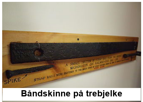
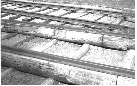
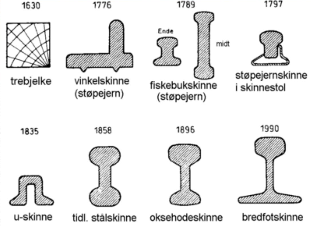
Figur 2.1 viser utviklingen av skinnetverrsnittet fra de tidligste jernbanene til dagens bredfotprofil (Vignole), som nå brukes over hele verden:
-
Tre- eller støpejernsbåndskinner (fra 1630) festet til trebjelker.
-
Støpejernskantskinne og fiskebukprofil (1776–1789).
-
U-profil (kanalskinne, 1835) og dobbelthodet skinne (bullhead, 1858).
-
Oksehodeprofil (1896).
-
Moderne bredfotskinne (flatbunnet skinne/Vignole-skinne), som nå er den universelle internasjonale standarden.
2.5.3 Skinneprofiler i Norge
Betegnelsessystemet følger UIC/EN-konvensjonen: Tallet angir masse per lengdeenhet i kg/m, og bokstavene identifiserer profilgeometrien [85, 10]. Tabell 2.2 viser profilene som finnes på det norske jernbanenettet.
| Profil | Masse [kg/m] | Merknader |
|---|---|---|
| 35 kg | 35 | Gammel profil; fortsatt i bruk på enkelte sidebaner |
| NSB40 | 40 | Tidligere NSB-standard |
| S41 | 41 | Tidligere standard |
| 49E1 | 49 | Mye brukt på strekninger i klasse c; fotbredde 125 mm |
| 54E1/E2/E3 | 54 | Standard for klasse c; 54E3 har samme fotbredde som 49E1 |
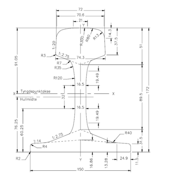
| 60E1 | 60 | Brukes i standardkonstruksjoner for klasse c og d; \(I_y = 3\,055 \times 10^4\,\mathrm{mm}^4\), \(W_{yf} = 335 \times 10^3\,\mathrm{mm}^3\) |
| 60E2 | 60 | Brukes i konstruksjonen BN24 W30, som er utviklet spesielt for Ofotbanen; litt større hoderadier enn 60E1 |
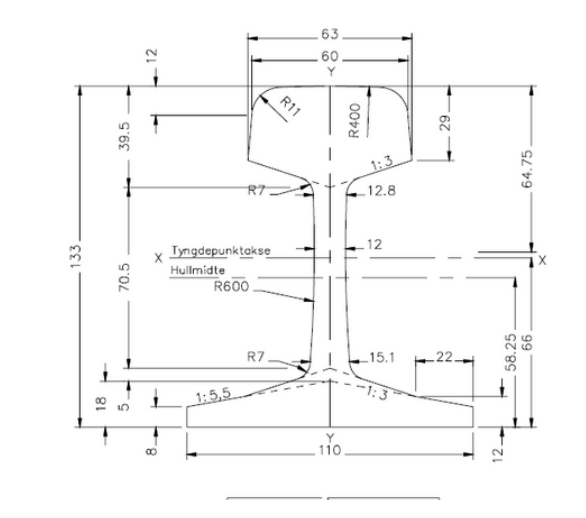
Profilene 60E1 og 60E2 brukes i standardkonstruksjonene som er oppført senere i tabell 2.4. Bruken av 60E2 på Ofotbanen er tilpasset malmtrafikk med normalt 30 t aksellast. Verdien 31 t er en øvre grense knyttet til infrastrukturen og særregler, og forutsetter godkjenninger; den er ikke en generell driftstillatelse. Kombinasjonen 49E1/54E3 brukes i spor i klasse c med konstruksjonen JBV54 FE. Figur 2.2 sammenligner et gammelt, lett skinneprofil med dagens 60E1-bredfotprofil.
2.5.4 Skinnestålets metallurgi
Skinnestål er et perlittisk stål med høyt karboninnhold. De mekaniske egenskapene styres gjennom legeringselementer og varmebehandling:
-
Karbon (C, 0,4–0,8 %): øker hardheten, men reduserer seigheten og sveisbarheten.
-
Mangan (Mn, 0,6–1,8 %): øker fastheten, slitasjemotstanden og seigheten ved lav temperatur, men reduserer sveisbarheten.
-
Silisium (Si, 0,13–1,12 %): deoksyderer smelten og hindrer porøsitet fra oksygen.
-
Krom (Cr) og vanadium (V, 0–1,3 % totalt): øker hardheten og slitasjemotstanden, men reduserer seigheten og sveisbarheten.
-
Urenheter (S, P, O, H, N): er uønskede og reduserer seigheten og sveisbarheten.
2.5.5 Skinnekvaliteter og Bane NORs utvalgskriterier
Kvaliteten på skinnestål angis ved minste strekkfasthet [165, 85]. Bane NOR bruker følgende kvaliteter:
-
R200 (680 MPa): utgått; finnes bare i gamle spor.
-
R260 (880 MPa): standardkvalitet uten forhøyet Mn-innhold.
-
R260Mn (880 MPa): standardkvalitet med forhøyet Mn-innhold og bedre seighet ved lav temperatur. Bane NORs standardkvalitet for rettlinjet spor og kurver med stor radius.
-
R320Cr (1 080 MPa): Cr-legert og med høyere hardhet.
-
R350HT: Hodeherdet ved akselerert kjøling. Strekkfastheten er \(\approx 1\,175\) MPa. Kvaliteten brukes i krappe kurver der sideslitasje er dimensjonerende.
Det tekniske regelverket angir nødvendig skinnekvalitet som funksjon av kurveradius og årlig trafikktonnasje (tabell 2.3).
| Kurveradius \(r\) | Trafikk [MBT/år] | Påkrevd kvalitet |
|---|---|---|
| \(r > 500\,\mathrm{m}\) | alle | R260Mn |
| \(250\,\mathrm{m} < r \leq 500\,\mathrm{m}\) | \(< 5\) MBT | R260Mn |
| \(250\,\mathrm{m} < r \leq 500\,\mathrm{m}\) | \(\geq 5\) MBT | R350HT |
| \(r \leq 250\,\mathrm{m}\) | alle | R350HT |
Grenseverdiene skal leses bokstavelig: \(r=500\) m tilhører kategorien \(250<r\leq500\) m, og \(r=250\) m tilhører kategorien \(r\leq250\) m. Trafikkverdien er årlig bruttotonnasje i MBT/år, det vil si millioner bruttotonn per år.
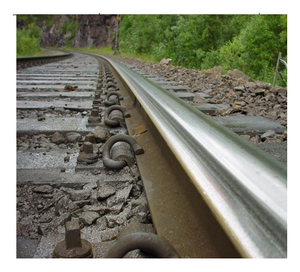
Figur 2.3 viser et typisk kurvespor der det kan være nødvendig med en skinne av høyere fasthet eller en hodeherdet skinne.
Merk at R350HT i rettlinjet spor eller kurver med stor radius ikke gir noen slitasjefordel sammenlignet med R260Mn. Hvis slitasjehastigheten er lav, kan kvaliteten tvert imot fremme rullende kontaktutmattelse (RCF) [68, 120]. På Ofotbanen kjører malmtogene normalt med 30 t aksellast. Den øvre grensen på 31 t, som er knyttet til infrastrukturen og særregler, forutsetter fortsatt godkjenninger. På Ofotbanen og Dunderlandsbanen kan slik tungtrafikk kreve spesialkvaliteter med enda høyere strekkfasthet.
Skinnene leveres fra valseverket i lengder på 40–120 m og forhåndssveises til skinnestrenger på 120–400 m ved stasjonær brennstuksveising før transport til anleggsstedet [84].
2.5.6 Skinnesveising
Helsveist spor (CWR) eliminerer de dynamiske støtene ved skjøter og er standarden for hovedspor. I praksis brukes to sveisemetoder for å skjøte skinneender ved framstilling av helsveist spor og ved sluttsveising i sporet.
Elektrisk motstandssveising (brennstuksveising).
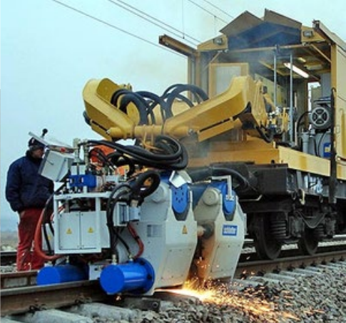
Høy elektrisk strøm og stor trykkraft påføres skinneendene samtidig. Endene varmes til smitemperatur og presses sammen. Sveisingen utføres i et sveiseverk (for lange skinnestrenger) eller med en mobil maskin i sporet ved slutt- og nøytraliseringssveiser.
Aluminiotermisk skjøtsveising.
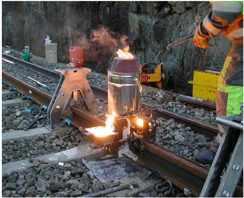
Den eksoterme reaksjonen mellom jernoksid og aluminium (termitten) produserer flytende stål ved omtrent \(2\,500\,{}^\circ\mathrm{C}\). Stålet helles i en form rundt skinnespalten og størkner slik at endene sveises sammen. Metoden brukes til sluttsveiser i sporet når en ny skinnestreng settes inn i en eksisterende helsveist skinnestreng.
De to sveisemetodene sammenlignes i figur 2.4, som viser aluminiotermisk skjøtsveising i sporet ved siden av en mobil maskin for elektrisk motstandssveising.
Det tekniske regelverket krever at alle sveiser ultralydkontrolleres etter utførelse, og at det ferdige sveiseprofilet oppfyller toleransene for skinnehodet i den relevante europeiske standarden [84, 81].
2.5.7 Skinneskjøter
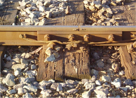
Der en fysisk spalte i skinnen er uunngåelig (ved seksjonsgrenser for signalanlegg eller på broer), brukes følgende skjøtetyper:
Laskeskjøter.
Konvensjonelle skrudde skjøter med stållasker. De brukes sjelden i moderne hovedspor fordi de gir dynamiske støtlaster og krever omfattende vedlikehold.
Midlertidig laskede skjøter.
Brukes etter skinnebrudd eller under sporarbeid. De gir mekanisk kontinuitet, men kan ikke overføre fullt bøyemoment.
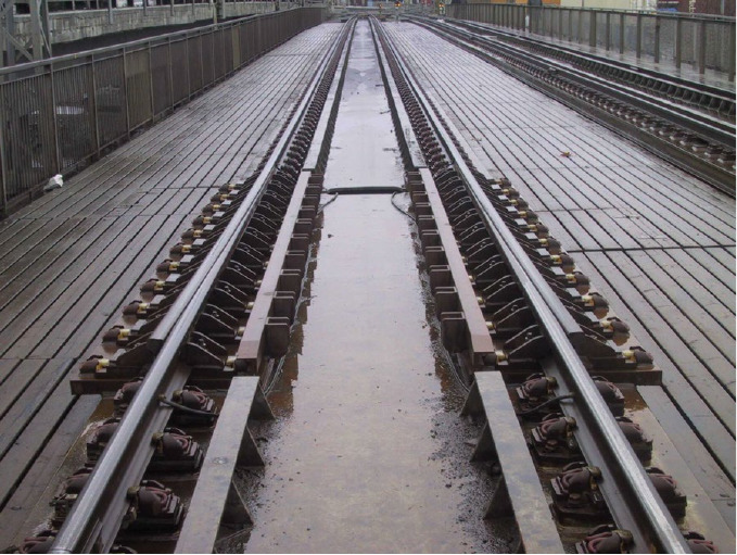
Glideskjøter.
Brukes på broer for å tillate langsgående skinnebevegelse der skinnen krysser en konstruksjon med en annen temperaturutvidelse enn helsveist spor på fri linje.
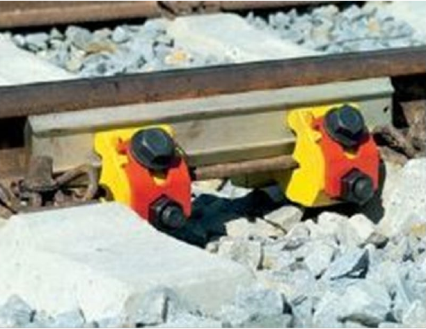
Figur 2.5 viser hvordan disse skjøtetypene ser ut i praksis.
Isolerte skjøter.
Elektrisk isolerende skjøter som skiller tilstøtende sporfeltseksjoner. Tre typer brukes:
-
MT-skjøt: limt isolasjonsmateriale mellom skinneende og lask. Historisk den vanligste typen; monteres ikke lenger på grunn av helse- og sikkerhetsfare ved avgasser.
-
S-skjøt (skråskjøt): prefabrikkert og limt på fabrikk, med skrått skinnesnitt. Høyere kvalitet enn MT; dagens standard for isolerte skjøter.
-
Excel-skjøt: lastoverførende laskekonstruksjon der langsgående spenninger tas opp av lasken i stedet for av den isolerende grenseflaten.
2.5.8 Skinnefeil
Skinnefeil klassifiseres som innvendige feil (under overflaten) eller overflatefeil. Her gis bare en kort oversikt. Skinnefeil, kontrollmetoder, klassifisering og vedlikeholdstiltak behandles mer detaljert i kapittel 4.
Innvendige feil.
-
Tverrsprekk/nyrebrudd: vokser fra et initieringspunkt under overflaten (vanligvis en hydrogeninneslutning eller en ikke-metallisk inneslutning) og forplanter seg på tvers gjennom skinnehodet. Feilen kan gi plutselig brudd og påvises ved ultralydkontroll.
-
Horisontal sprekk: forplanter seg parallelt med løpeflaten, ofte i overgangen mellom steg og hode.
-
Vertikal sprekk: forplanter seg nedover gjennom steget.
Overflatefeil og feil nær overflaten.
-
Avskalling: RCF-sprekker under overflaten vokser sammen og medfører materialtap fra skinnehodet, vanligvis ved kjørekanten eller på toppen av hodet.
-
Kjørekantsprekker («head checks»): fine overflatesprekker ved kjørekanten, forårsaket av RCF i kurver; de forplanter seg med liten vinkel inn i hodet.
-
Squat-feil: brede, grunne overflatefeil på toppen av skinnen, forbundet med en W-formet nedsenkning i løpeflaten. De initieres av små overflateujevnheter og utvikles videre ved plastisk flyt og RCF.
-
Hjulslag/sluresår: flate partier som oppstår når hjulet glir under bremsing. De gir kraftige støtkrefter for hver hjulomdreining.
Feil påvises ved periodiske kontroller med ultralydtraller og spormålevogner. Bane NORs tekniske regelverk angir kontrollintervaller og tiltaksgrenser for hver feiltype.
2.6 Befestigelse
Skinnebefestigelsen forbinder skinnen med svillen [88, 89]. Den skal overføre vertikale krefter, tverrkrefter og langsgående krefter fra skinnen, opprettholde riktig sporvidde og skinnehelning, gi elektrisk isolasjon, tillate kontrollert vertikal elastisitet, motstå utmatting og kunne monteres og skiftes raskt.
2.6.1 Ikke fjærende befestigelser
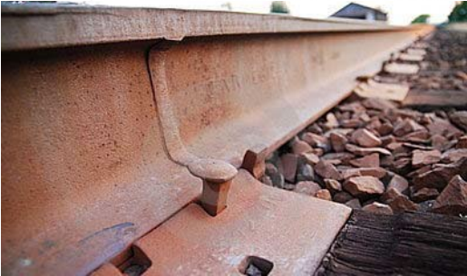
Skinnespiker («dog»).
En direkte, ikke fjærende befestigelse: En spiker med kvadratisk tverrsnitt slås gjennom en underlagsplate og ned i tresvillen ved siden av skinnefoten. Løsningen er enkel, men gir ingen klemkraft på skinnen. Den finnes bare i svært gamle eller lett belastede spor.
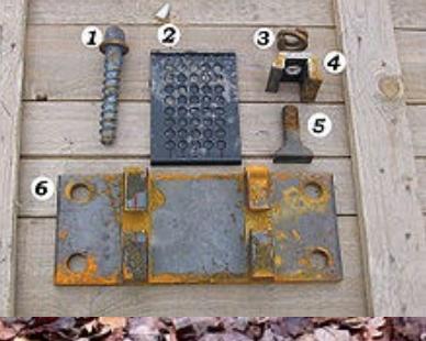
K-befestigelser (klemgods).
En indirekte, ikke fjærende klemme som er boltet til en underlagsplate festet med spiker til svillen. Den gir bedre sidestyring enn en skinnespiker alene.
Figur 2.6 sammenligner en direkte skinnespiker med en indirekte K-befestigelse og identifiserer hovedkomponentene i K-befestigelsen.
2.6.2 Fjærende befestigelser
Fjærende befestigelser bruker en fjærklemme som påfører skinnefoten en vedvarende klemkraft. Klemkraften hindrer skinnebevegelse under belastning og opprettholder den elektriske isolasjonen.
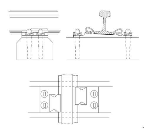
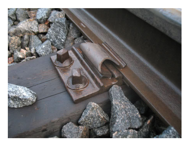
Hey-Back-befestigelse.
Befestigelsen ble utviklet av de norske jernbaneingeniørene Heyerdahl Larsen og Backe Hanson (derav navnet «Hey-Back»), patentert i 1942 og tatt i bruk i flere land, blant annet Sverige og Storbritannia. En fjærklemme med to ender griper inn i utsparinger i en underlagsplate og presser mot skinnefoten.
Figur 2.7 viser Hey-Back-løsningen både som prinsippskisse og som montert befestigelse.
Pandrol PR-klemme og E-klemme.
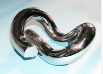
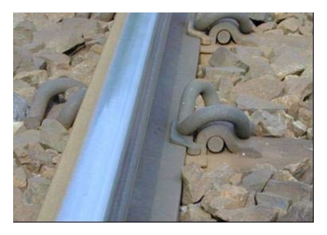
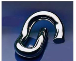
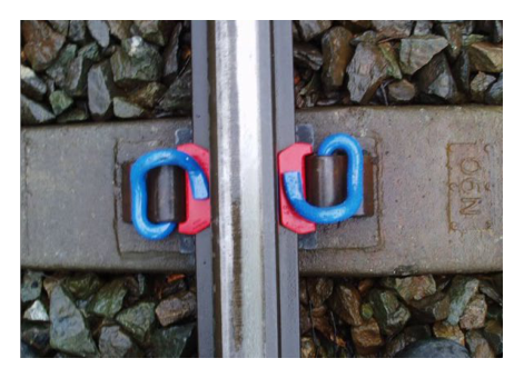
Løsningen ble utviklet av den norske jernbaneingeniøren Per Pande-Rolfsen (derav navnet «Pandrol»). En ensidig fjærklemme griper inn i et innstøpt svilleanker og presser mot skinnefoten. Den er billigere å produsere og montere enn Hey-Back og gir større og mer varig klemkraft. E-klemmen er en videreutviklet variant med bedre fjæregenskaper.
Figur 2.8 sammenligner PR-klemmen og E-klemmen både som løse komponenter og som monterte befestigelser.
Pandrol Fastclip FE [10, 88] (gjeldende Bane NOR-standard).
Fastclip har større klemkraft enn PR-/E-klemmen og kan forhåndsmonteres på svillen på fabrikken før levering til anleggsstedet. Dette reduserer tiden for sporbygging vesentlig. Gjeldende standard er Pandrol Fastclip FE 1404 med JBV 60 Dual Rail-anker (for både 49E1/54E3- og 60E1-profiler) eller JBV 54-anker (bare 49E1/54E3).
Figur 2.9 viser Fastclip i forhåndsmontert og låst stilling.
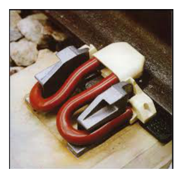
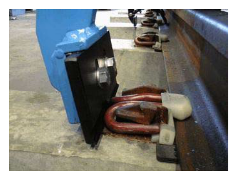
Dual Rail-konseptet gjør at én svillevariant kan brukes med to forskjellige skinneprofiler (for eksempel kan JBV 60 Dual Rail brukes med både 49E1/54E3 og 60E1). Svillen trenger derfor ikke å skiftes når skinneprofilet oppgraderes.
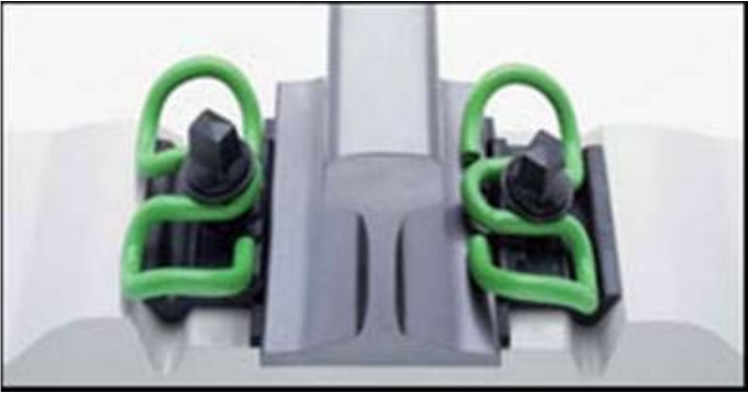
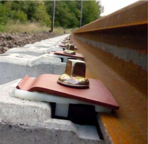
Andre befestigelsessystemer som brukes internasjonalt, men er mindre vanlige i Norge, er Vossloh W30 (brukt på Ofotbanen med 60E2 og BN 24-sville) og det franske Nabla-systemet (brukt i enkelte tunneler med begrenset plass), vist i figur 2.10.
2.6.3 Befestigelseskomponenter
Mellomlegg.
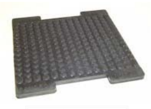
Mellomlegget plasseres mellom skinnefoten og svillen (eller underlagsplaten). Hovedfunksjonene er å redusere største kontakttrykk, gi kontrollert vertikal elastisitet (statisk stivhet 40–60 kN/mm per mellomlegg) og gi elektrisk isolasjon. Gjeldende standard er et 10 mm gummimellomlegg. Tidligere ble det brukt 5 mm EVA-plast. Mykere mellomlegg gir større demping, men tillater større skinnevridning og kan fremskynde utmatting i fjærklemmene. Mellomlegg må vurderes sammen med svillematter (avsnitt 2.7.6) for å unngå resonans og for stor samlet nedbøyning.
Isolatorer.
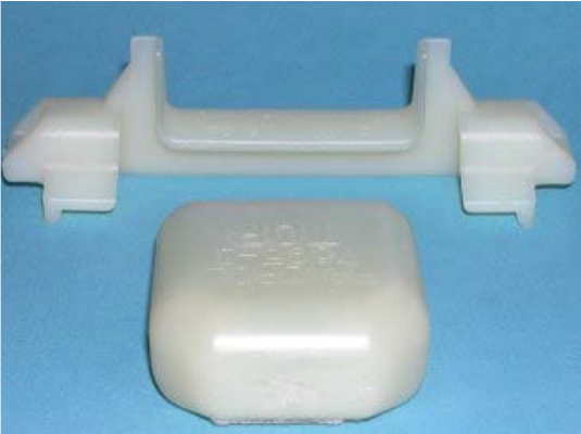
Tå- og skulderisolatorer av plast hindrer elektrisk kontakt mellom fjærklemmen og skinnefoten. De er fargekodet etter skinneprofil og befestigelsestype for å hindre monteringsfeil.
Svilleankre.
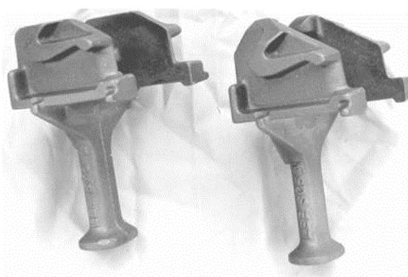
Ankrene støpes inn i svillen under produksjonen og danner anlegget som fjærklemmen griper i. Geometrien er spesifikk for befestigelsessystemet og svilletypen.
De enkelte mellomleggene, isolatorene og ankrene vises i figur 2.11.
2.6.4 Standardiserte sporkonstruksjoner i Bane NORs tekniske regelverk
Tabell 2.4 gjengir tabellen i det tekniske regelverket over standardiserte sporkonstruksjoner for nybygging og sporfornyelse.
| Betegnelse | Skinne | Befestigelse | Sville | Klasse |
|---|---|---|---|---|
| JBV60 FE | 60E1 | Pandrol FE 1404 Fastclip | Betong JBV 60 | d |
| BNF60 FE | 60E1 | Pandrol FE 1404 Fastclip | Betong BNF 60 | d |
| BN24 W30 | 60E2 | Vossloh W30 | Betong BN 24 | Ofotbane-spesifikk |
| JBV54 FE | 49E1/54E3 | Pandrol FE 1404 Fastclip | Betong JBV 54 | c |
2.6.5 Regneeksempel: valg av komponenter etter overbygningsklasse
Oppgave. Gjør et foreløpig valg av overbygning for en ny, dobbeltsporet hovedstrekning med overbygningsklasse d, minste kurveradius \(r=1000\) m og årlig bruttotonnasje 12 MBT/år. Angi skinneprofil og skinnekvalitet, standardisert sporkonstruksjon, befestigelse og sville, og vurder om friksjonssville eller svillematte automatisk er påkrevd.
Trinn 1: bekreft dimensjonerende klasse. Prosjektkravet er klasse d. Av tabell 2.1 framgår det at denne klassen dekker hastighets- og aksellastområdet som brukes ved nybygging av hovedspor. Klassen behandles derfor som en inngangsparameter ved valg av komponenter, ikke som noe som utledes av årlig tonnasje alene.
Trinn 2: velg skinneprofil og skinnekvalitet. Tabell 2.4 viser 60E1-skinne for JBV60 FE-konstruksjonen i klasse d. Fordi \(r>500\) m, krever tabell 2.3 R260Mn uavhengig av årlig tonnasje. Verdien 12 MBT/år ville først vært utslagsgivende i området \(250<r\leq500\) m. Å spesifisere R350HT her ville øke hardheten uten et dokumentert slitasjebehov og kunne redusere den gunstige slitasjen som fjerner grunne skader fra rullende kontaktutmattelse.
Trinn 3: velg standardisert konstruksjon. Et konsistent foreløpig valg er:
| Element | Valg | Begrunnelse |
|---|---|---|
| Skinne | 60E1, kvalitet R260Mn | Standardprofil for klasse d; \(r>500\) m bestemmer kvaliteten. |
| Befestigelse | Pandrol FE 1404 Fastclip | Samsvarer med standardkonstruksjonen JBV60 FE og gir elastisk fastholding. |
| Sville | Betong JBV 60 | Standard sville for klasse d med valgt befestigelse. |
| Konstruksjon | JBV60 FE | Komplett standardkonstruksjon fra Bane NOR, ikke en vilkårlig kombinasjon av komponenter. |
| Friksjonssville | Ikke påkrevd i dette tilfellet | Kurveradiusen 1000 m gir ikke behovet for fastholding i krapp kurve som ligger til grunn for BNF60. |
| Svillematte | Prosjektspesifikt alternativ | Brukes bare der overgangsstivhet, vibrasjoner eller kontaktforhold mot ballasten tilsier det. |
Ingeniørfaglig kontroll. Valget gir en kompatibel overbygning, men fullfører ikke spordimensjoneringen. Bæreevnen i formasjonsplanet, drenering, ballastprofil, stabilitet i helsveist spor, overgangssoner, sporveksler og vedlikehold gjennom levetiden krever fortsatt egne kontroller. På et industrispor med radius 150 m fjerner ikke lav hastighet behovet for å kontrollere slitasje og fastholding i krapp kurve i tillegg til grunnleggende komponentkompatibilitet.
2.7 Sviller
Svillene opprettholder sporvidden, fordeler trykket fra skinnefoten over ballasten, gir sideveis og langsgående motstand mot sporbevegelse, holder skinnen i riktig helning (1:20 for nye spor) og fester befestigelsessystemet [130, 148].
2.7.1 Tresviller
I dag brukes hardtresviller (bøk/eik fra Tyskland og Tsjekkia). Norsk furu, som tidligere var det vanlige materialet, er faset ut.
Fordeler.
Lav vekt (60–80 kg) gjør svillene enkle å håndtere uten maskiner. God naturlig elastisitet reduserer følsomheten for støtlaster og stiller mindre krav til ballastkvaliteten. Svillene kan bores, sages og tilpasses i sporet.
Ulemper.
Svillene er utsatt for råte: Skruehullene utvides, og underlagsplatene graver seg ned slik at befestigelsene løsner. De gir mindre sidemotstand enn betongsviller og er mer utsatt for solslyng.
Kreosotimpregnering er klassifisert som kreftfremkallende og har vært forbudt siden 2018. Erstatningsmiddelet «Sleeper Protect» har begrenset dokumentert brukstid.
Levetid.
15–40 år, avhengig av treslag, belastning og drenering.
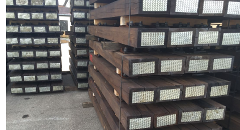
Figur 2.12 viser tresviller klargjort for montering.
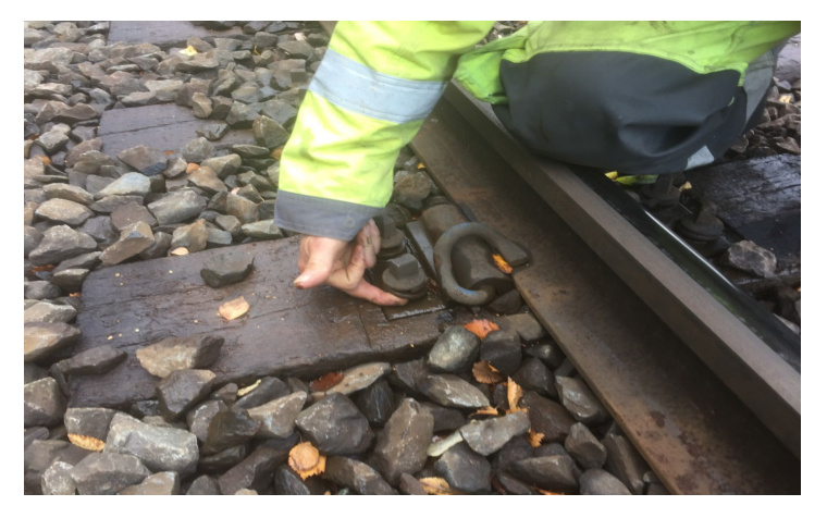
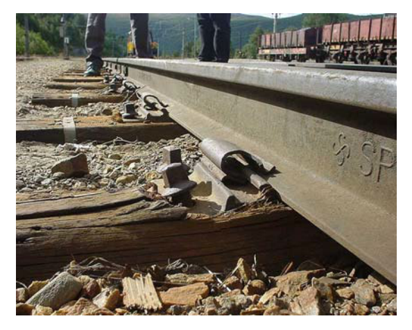
Når tresviller brytes ned, opptrer skadene ofte rundt skinnesetet. Typiske skadeformer er underlagsplater som skjærer seg ned i svillen, oppsprekking og lokal knusing rundt befestigelsen.
2.7.2 Brusviller
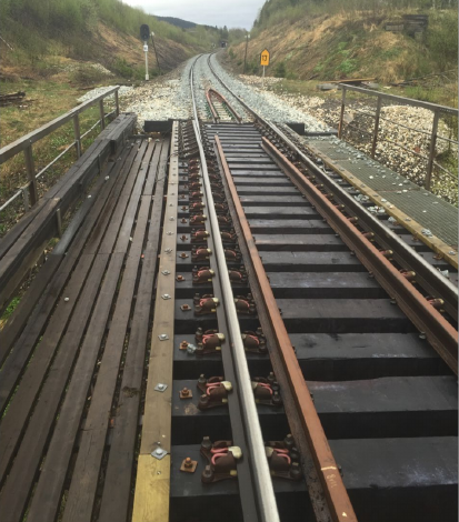
Brusviller er spesielle tresviller som brukes på broer med åpent brudekke og i andre brodetaljer der vanlig, ballastert svilleunderstøttelse ikke er tilgjengelig. De skal gi skinneunderstøttelse, holde sporvidden og forbinde sporet med brudekket, samtidig som de tilpasses gangbaner, ledeskinner og brospesifikke befestigelsesdetaljer, som vist i figur 2.14.
2.7.3 Komposittsviller
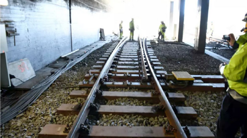
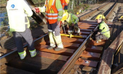
Komposittsviller framstilles av polymerbaserte materialer (vanligvis resirkulert plast eller glassfiberarmert harpiks). De kan bores og tilpasses på samme måte som tresviller. Levetiden er \(\geq 40\) år. Det forventes at de gradvis vil erstatte tresviller når de langsiktige virkningene av kreosotforbudet slår inn og treprisene stiger. Figur 2.15 viser komposittsviller både i sporet og under montering.
2.7.4 Betongsviller
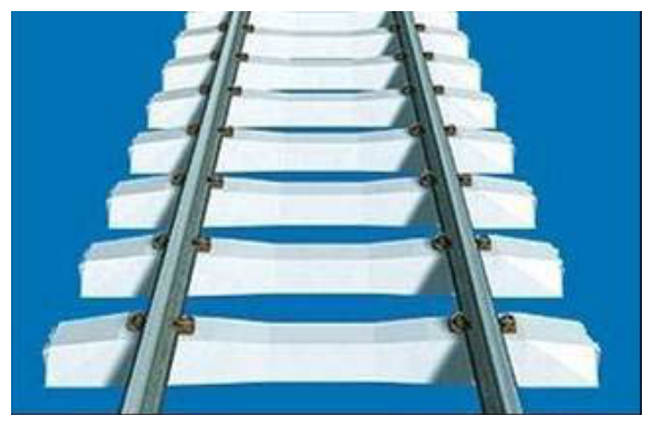
Forspente betongsviller i ett stykke (monoblokk) er standard ved all nybygging og større fornyelser på det norske hovednettet [10, 130].
Egenskaper.
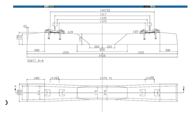
Den høye vekten (240–300 kg) gir stor sideveis og langsgående motstand. Svilleankrene støpes inn på fabrikken. Svillene kan ikke bores eller tilpasses i sporet uten å svekke armeringen. Betongsviller er langt stivere enn tresviller, slik at den elastiske nedbøyningen er liten sammenlignet med ettergiveligheten i mellomlegg, ballast og underbygning. For stor eller ujevn understøttelse i ballasten kan likevel gi bøyning og oppsprekking, og tilstrekkelig ballasttykkelse og jevn understøttelse er derfor avgjørende. De råtner ikke, og levetiden er vanligvis 40–50 år.
Figur 2.16 viser standard monoblokkutførelse og typisk geometri.
Typiske skader.
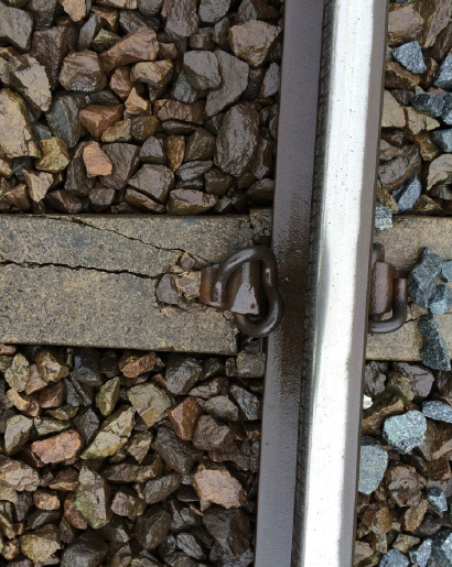
Alkali–silika-reaksjon (ASR): Alkalier fra sementen reagerer med reaktiv silika i tilslaget når vann er til stede. Det dannes en svellende gel som gir innvendig oppsprekking. Sprekkene er vanligvis langsgående og parallelle. Ved lav temperatur utvikles de langsomt (\(>20\) år), men utviklingen går raskere når sprekkbredden overstiger 1 mm på grunn av frost. Sprekker som når det innstøpte ankeret, er særlig kritiske. Sviller fra norske produksjonsserier før omtrent 1990 er berørt.
Figur 2.17 viser en ASR-skadet sville.
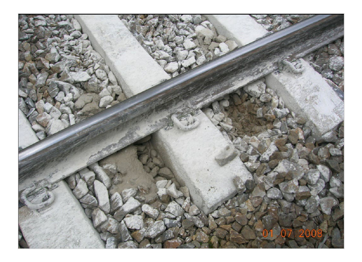
Knusing fra ballasten på undersiden (vaskesviller/knusing): Hvis ballastlaget er for tynt over et hardt formasjonsplan, slites undersiden av svillen bort. Dårlig drenering fremmer «pumping» av svillen under våte forhold, etterfulgt av knusing mot et hardt underlag under tørre forhold.
Figur 2.18 viser et typisk skademønster på undersiden.
2.7.5 Friksjonssville BN60
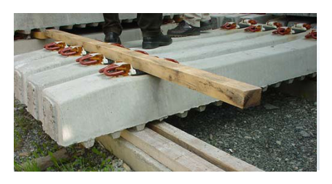
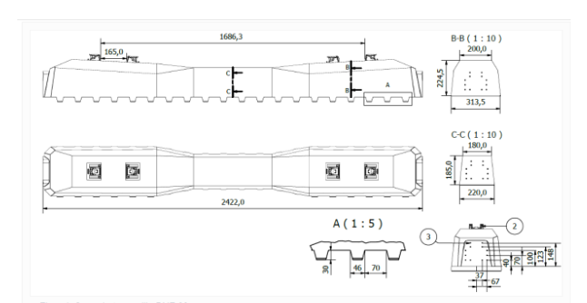
BN60-friksjonssvillen er en spesialutformet betongsville som øker sidemotstanden i kurver ved å flytte skjærplanet fra den glatte svilleundersiden og inn i ballastlegemet, der den indre friksjonen er større. Figur 2.19 viser den profilerte undersiden.
Krav i teknisk regelverk:
-
Obligatorisk: Bruk BN60-friksjonssviller ved nybygging og sporfornyelse der kurveradius \(r < 250\,\mathrm{m}\).
-
Anbefalt: Bruk BN60-friksjonssviller der \(250\,\mathrm{m} \leq r \leq 300\,\mathrm{m}\).
Kompatible skinneprofiler: 49E1, 54E3 og 60E1.
2.7.6 Svillematter (USP)
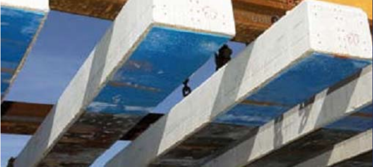
Svillematter (USP) er elastiske gummimatter som limes til undersiden av betongsviller, som vist i figur 2.20. De reduserer knusespenningen i ballasten, gir ekstra vertikal elastisitet på stive steder (broer, stikkrenner) og demper strukturlyd og vibrasjoner.
Det tekniske regelverket angir den arealspesifikke statiske stivheten \(C_\mathrm{STAT}\) (N/mm\(^3\)) som funksjon av svilletypen (tabell 2.5).
| Svilletype | \(C_\mathrm{STAT}\) [N/mm\(^3\)] |
|---|---|
| JBV 60 (standard) | 0,10–0,15 |
| JBV 60 (stivere variant) | 0,25–0,30 |
| OB35 HAL | 0,25–0,30 |
| JBV 60 Ofotbanen | 0,30–0,35 |
| JBV 54 (mykere) | 0,15–0,20 |
| JBV 54 (stivere) | 0,25–0,30 |
Bruksregler (teknisk regelverk):
-
\(C_\mathrm{STAT} \leq 0{,}15\,\mathrm{N/mm^3}\): tillatt der full ballasttykkelse ikke kan oppnås (tykkelsen kan reduseres med opptil 100 mm), og ved brå stivhetsoverganger (stikkrenner, brokar).
-
\(C_\mathrm{STAT} \leq 0{,}35\,\mathrm{N/mm^3}\): tillatt på fri linje for å redusere nedbrytning av ballasten og dempe kortbølgede rifler på innerskinnen i kurver.
-
Svillematter skal ikke kombineres med ballastmatter eller isolasjonsplater av XPS. Det kan gi ugunstige resonansvirkninger og for stor nedbøyning.
2.7.7 Sammenligning av svilletyper
Valget av sville er en avveining mellom kostnad, masse, elastisitet, mulighet for tilpasning under fornyelsesarbeid og forventet levetid.
| Egenskap | Tre | Kompositt | Betong |
|---|---|---|---|
| Kostnad (inkl. befestigelse) | \(\approx 3\,600\) NOK | \(\approx 3\,300\) NOK | \(\approx 900\) NOK |
| Masse | 60–80 kg | 70–80 kg | 240–300 kg |
| Svilleettergivelighet | Relativt stor | Relativt stor | Liten; systemets elastisitet kommer fra mellomlegg og understøttelseslag |
| Tilpasning i sporet | Ja | Ja | Svært begrenset |
| Levetid | 15–40 år | \(\geq 40\) år | 40–50 år |
| Viktigste skadeform | Råte | Ikke relevant | ASR-oppsprekking |
2.8 Ballastfritt spor
Ballastfritt spor tas med som en kontrast til konvensjonelt ballastert spor, fordi løsningen endrer hvordan understøttelsesstivhet, setninger, fornyelse og vedlikehold håndteres.
2.8.1 Prinsipp og egenskaper
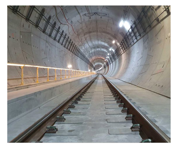
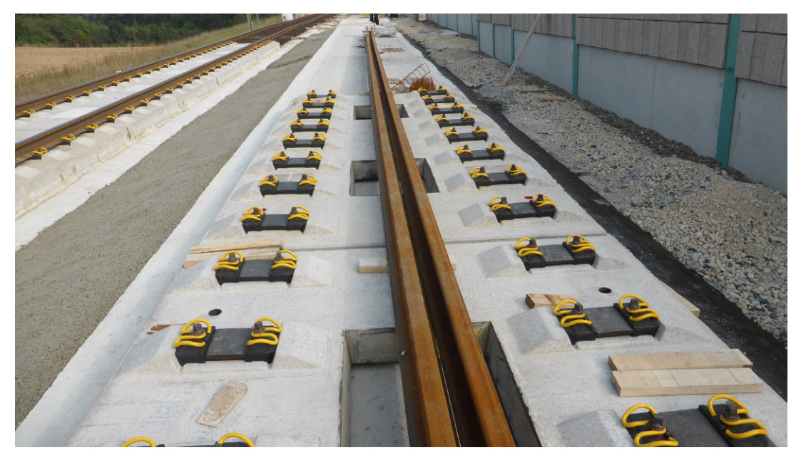
Ballastfritt spor (fastspor) er en sporkonstruksjon der skinner og befestigelser monteres på en kontinuerlig armert betongplate eller et asfaltdekke i stedet for på separate sviller i et ballastlag. Figur 2.21 viser eksempler fra tunnel og prefabrikkerte plater.
Fordeler.
Vesentlig lavere konstruksjonshøyde reduserer tunneltverrsnittet og utgravingskostnaden. Vedlikeholdsbehovet er svært lite: Det er ikke behov for pakking eller ballastfornyelse [68]. Sporgeometrien er svært stabil over tid.
Ulemper.
Anleggskostnaden er vesentlig høyere. Muligheten for å justere geometrien er svært begrenset: Små korreksjoner krever utskifting av mindre befestigelseskomponenter, mens store korreksjoner krever at platen pigges opp og bygges på nytt. Setninger i undergrunnen under platen er svært vanskelige å rette. Løsningen kan ikke kombineres med sporveksler og sporkryss med mindre hele sporvekselområdet ligger innenfor platestrekningen.
2.8.2 Bruk i Norge
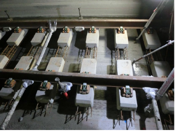
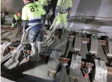
Ballastfritt spor er hittil tatt i bruk i Ulriken- og Blix-tunnelene. Den lave konstruksjonshøyden er særlig verdifull i tunneler. Ballastfritt spor brukes også på broer og kan i prinsippet brukes på fri linje, men risikoen for differansesetninger gjør bruk på fri linje krevende. Figur 2.22 viser byggerekkefølgen i Ulriken-tunnelen.
2.8.3 Standardiserte konstruksjoner for ballastfritt spor i Bane NORs tekniske regelverk
Det tekniske regelverket angir tre standardiserte Rheda 2000-systemer for ballastfritt spor, alle klassifisert som klasse d:
-
Rheda 2000 VIPA DFC: 60E1-skinne, Pandrol VIPA DFC-befestigelse og tvillingblokksville B 355.3-DFC innstøpt i betongplaten.
-
Rheda 2000 Fastclip FCA: 60E1-skinne, Pandrol Fastclip FCA-befestigelse og tvillingblokksville B 355.3-FCA innstøpt i platen.
-
Rheda 2000 Vanguard/VIPA DFC-ettermontering: brukes til å oppgradere eksisterende Rheda-plater med et nytt befestigelsessystem uten å bygge platen på nytt.
2.9 Oppsummering
Systemfunksjon. Skinner, befestigelser og sviller virker sammen for å bære hjullaster, opprettholde sporvidden, styre hjulsatsene og fordele kreftene til ballasten eller platen. Skinnen er løpeflate og hovedbjelke, men kan ikke fungere riktig uten at befestigelsessystemet holder den på plass og svillen gir stabil understøttelse. Overbygningen må derfor velges som et system, ikke som en liste over uavhengige komponenter.
Skinner og stål. Skinneprofiler som UIC 54 og 60E1 har ulik bøyekapasitet, hodeflate, slitasjereserve og kompatibilitet med moderne overbygningsklasser. Valg av skinnekvalitet er også viktig: Standardkvaliteter kan være egnet ved moderate forhold, mens hodeherdede kvaliteter eller spesialkvaliteter brukes når kurvatur, aksellast, trekkraft eller slitasjehastighet tilsier den ekstra ytelsen. Profil og skinnekvalitet knytter dermed den mekaniske dimensjoneringen til vedlikeholdsplanleggingen.
Befestigelser. Ikke fjærende befestigelser er historisk viktige, men moderne spor bruker vanligvis fjærende systemer som gir klemkraft, fastholding av sporvidden, isolasjon ved skinnesetet og kontrollert elastisitet. Befestigelsesstivheten påvirker skinnenedbøyning, vibrasjoner, støy, tendens til rifler og bølger samt lasten som overføres til svillen og ballasten. Valg av befestigelse er særlig viktig i kurver, på broer, i ballastfritt spor og andre steder der langsgående eller sideveis fastholding må kontrolleres nøye.
Sviller. Tresviller, brusviller, komposittsviller, betongsviller, friksjonssviller og betongsviller med svillematter løser ulike jernbanetekniske oppgaver. Betongsviller er standarden i hovedspor med høy kapasitet fordi de gir masse, dimensjonsstabilitet og gode forhold for befestigelsen, mens tre- og komposittsviller fortsatt er relevante på spesielle steder. Svillene påvirker også ballasttrykket, sporstivheten, pakkingen og muligheten for å opprettholde geometrien over tid.
Sporkonstruksjon. Ballastert spor er justerbart og velkjent, men geometrien avhenger av ballasttilstanden og periodisk vedlikehold. Ballastfritt spor gir et mer stabilt understøttelsessystem med mindre behov for geometrivedlikehold, men krever nøyaktig bygging og er vanskeligere å korrigere dersom det oppstår setninger. Riktig valg avhenger av trafikk, begrensninger i tunneler eller på broer, tilgang for vedlikehold, livsløpskostnad og hvor lange driftsavbrudd som kan aksepteres.
Oppgaver
Oppgave 1: Overbygningens funksjoner og komponenter
Sporets overbygning skal styre kjøretøyet, overføre laster, gi kontrollert elastisitet og kunne vedlikeholdes gjennom hele levetiden.
(a) Beskriv hovedfunksjonene og kravene til sporets overbygning.
(b) Oppgi minst seks hovedkomponenter eller elementer i overbygningen, og angi funksjonen til hver av dem. Ta med kjernekomponentene i et ballastert spor, og forklar hvordan spesielle elementer som sporveksler og ballastfritt spor inngår i overbygningen.
(c) Bruk tabellen over overbygningsklasser til å forklare hva som bestemmer nødvendig overbygningsklasse, og oppgi de oppførte kombinasjonene av aksellast og hastighet i klasse d for gods- og arbeidskjøretøy.
(d) Forklar hvorfor elastisitet og elektrisk isolasjon ikke er valgfrie tilleggsdetaljer, men inngår i den funksjonelle utformingen av overbygningen.
Oppgave 2: Komponentvalg etter overbygningsklasse
Bane NOR vurderer to tilfeller for valg av komponenter:
Tilfelle A: En ny, 4 km lang dobbeltsporet hovedstrekning (overbygningsklasse d). Minste kurveradius er 1 000 m, og prognosen for årlig tonnasje er 12 MBT/år.
Tilfelle B: Et sidespor til en papirfabrikk, tilknyttet et spor i klasse d, skal oppgraderes. Minste kurveradius på sidesporet er 150 m. Eieren ønsker å tillate 22,5 t aksellast, men driftshastigheten forventes ikke å overstige 30 km/h.
(a) Velg egnet skinneprofil, skinnekvalitet, betegnelse på standardisert sporkonstruksjon, befestigelsestype og svilletype for tilfelle A. Angi om friksjonssviller er påkrevd, og om svillematter kan brukes.
(b) Foreslå egnede skinner, befestigelser, sviller, ballast/elastiske elementer og eventuelle særskilte kontroller for tilfelle B, der kurveradiusen bare er 150 m.
(c) Forklar prinsippet for Pandrol Fastclip FE ved valg av befestigelse, og oppgi det typiske området for statisk stivhet til standardmellomlegget på 10 mm som brukes med systemet.
(d) Sammenlign de to valgene, og forklar hvorfor et lavhastighetssidespor fortsatt kan kreve omhyggelig utforming av overbygningen.
Oppgave 3: Identifisering av sporfeil
En sporkontrollør finner følgende tre feil:
(i) Fine, diagonale overflatesprekker ved kjørekanten på ytterskinnen i en kurve (\(r = 350\,\mathrm{m}\)).
(ii) En bred, grunn nedsenkning med W-form sett ovenfra på toppen av skinnen i rettlinjet spor.
(iii) Parallelle langsgående sprekker på undersiden av betongsviller produsert før 1990.
(a) Navngi hver feiltype og den grunnleggende årsaken.
(b) Angi om hver feil har sitt opphav i utmatting, slitasje, kjemi eller støt, og hvilken komponent som er hovedansvarlig.
(c) Hvilken feil er mest sikkerhetskritisk, og hvorfor?
Oppgave 4: Forringelse av geometrien i kurve
En kurve med radius 550 m på en strekning i klasse c (60E1-skinne, betongsviller, 130 km/h) har rask forringelse av sporgeometrien. Overhøyden er 130 mm. En kontroll på stedet viser slitte mellomlegg på 15% av svillene, 12 mm kjørekantslitasje på ytterskinnen, rifler med bølgelengde 120 mm på innerskinnen og en forurensningsindeks \(FI=38\) i ytre ballastskulder.
(a) Identifiser for hver feil hvilken sporkomponent som svikter, og hvilken mekanisme som virker.
(b) Beregn den relative reduksjonen i kjørekantslitasje dersom R350HT reduserer slitasjekoeffisienten med 35% sammenlignet med R260Mn under ellers identiske kontaktforhold. Forklar hvorfor hardhet alene ikke er en fullstendig slitasjemodell.
(c) Foreslå en prioritert utbedringsplan som omfatter alle de fire feilene.
Oppgave 5: Elastiske sportiltak
Støy og vibrasjoner fra tog kan bryte ned komponentene i overbygningen og forstyrre omgivelsene. En tunnelstrekning vurderes for elastiske sportiltak. Målet er å redusere passeringsstøyen med minst 3 dB(A). Sporets understøttelsesstivhet uten svillematte er \(C_t = 120\) kN/mm. En myk svillematte reduserer den til \(C_t = 60\) kN/mm.
(a) Identifiser tiltak i overbygningen som kan redusere nedbrytning av komponenter, støy og vibrasjoner. Ta med mellomlegg, svillematter og ballastmatter i drøftingen.
(b) Bruk den forenklede formelen for skinnenedbøyning under én aksellast (\(\delta = Q/C_t\)) til å sammenligne nedbøyningen med og uten svillematte for \(Q = 100\) kN. Kommenter konsekvensene for spenningsfordelingen i ballasten.
(c) Det hevdes at svillematter reduserer passeringsstøyen med omtrent 2–4 dB(A) i typiske installasjoner. Forklar den fysiske mekanismen som gjør at redusert sporstivhet gir mindre støy.
(d) Angi to ulemper ved myke svillematter som må håndteres i spordimensjoneringen, og forklar hvorfor svillematter ikke skal kombineres med ballastmatter eller XPS-isolasjonsplater.
Oppgave 6: Sammenligning av ballastert og ballastfritt spor
Sammenlign en norsk ballastert sporkonstruksjon i klasse d med en Rheda 2000 Fastclip FCA-konstruksjon for ballastfritt spor i klasse d.
(a) Sammenlign hovedkomponentene og prinsippene for lastunderstøttelse i de to systemene.
(b) Oppgi de viktigste fordelene og ulempene ved ballastert spor.
(c) Oppgi de viktigste fordelene og ulempene ved ballastfritt spor.
(d) Forklar hvorfor ballastfritt spor er særlig attraktivt i tunneler, men krevende på fri linje.