Track Substructure
4.1 Introduction
The track substructure comprises all load-bearing earthworks and civil structures that sit below the ballast or formation plane and ultimately transfer railway loads to the natural ground. While the superstructure (rails, fasteners, sleepers, ballast) is the focus of Chapters 2 and 3, the substructure determines the long-term stability, settlement behaviour, and operational reliability of the line.
The latest official Bane NOR sources available for this 2026 edition do not provide a single updated table with exactly the same categories. For orientation, the network operated by Bane NOR comprises approximately [28, 34]:
-
4,660 kilometres of main track
-
413 kilometres of tunnels
-
55 kilometres of bridges
-
336 railway stations in Bane NOR's property and service-facility portfolio
-
a continuing level-crossing reduction programme, with 117 level crossings closed in 2025
The high proportion of tunnels and bridges is a direct consequence of Norway's rugged topography. This chapter covers the three principal substructure types encountered in railway design: tunnels, cuttings, and embankments. For each type, the functional requirements, design principles, material requirements, stability considerations, and relevant Norwegian technical regulations are discussed.
4.2 Tunnels
Tunnels are introduced first because they combine alignment constraints, structural support, drainage, frost protection, and safety requirements in a confined railway environment.
4.2.1 Definition and Scope
A railway tunnel is defined as a closed structure that guides the track through a blasted, bored, or excavated underground passage. Bane NOR technical regulations for tunnels (section 02766 and associated subchapters) apply to:
-
New railway tunnels \(\geq 20\) m long with standard cross-section
-
Upgrading of existing tunnels (for train speeds \(\leq 250\) km/h)
-
Service tunnels, cross-passages, and evacuation tunnels
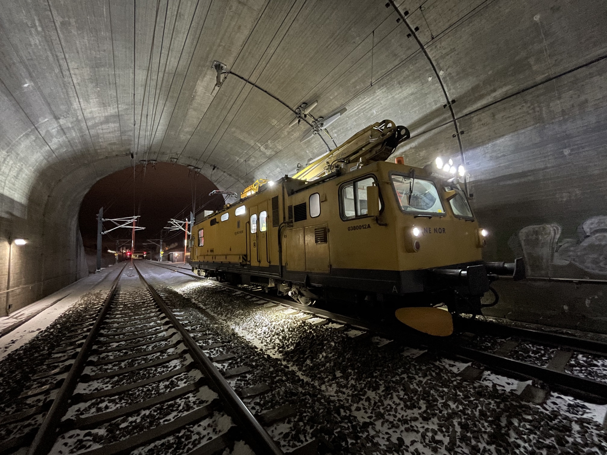
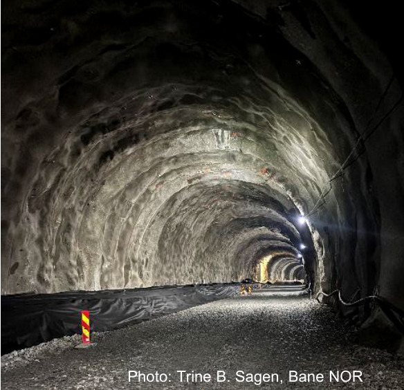
The design lifetime for the tunnel structure including waterproofing is 100 years. Figure 4.1 shows the kind of confined rock-tunnel environment where structural, drainage, electrification and maintenance requirements must work together.
4.2.2 Functional Requirements
A railway tunnel must do more than create an opening through terrain; it must also support safe railway operation, emergency access, inspection, and long-term maintenance:
-
Allow the railway line to pass through elevated terrain in a cost-effective way
-
Protect the environment from railway traffic, including both the natural environment and densely populated areas
-
Safety: safe for trains, passengers, and maintenance personnel
-
Reliability: reliable for traffic operation throughout the design life
-
Maintainability: easy to maintain with low downtime
4.2.3 Standard Tunnel Profile
The tunnel cross-section must accommodate the train's kinematic envelope, including structural gauge, catenary equipment, drainage installations, cable routes and walkways. In Norwegian rock tunnels, the standard profile is typically excavated by the drill-and-blast method. The resulting space claim is captured in Figure 4.2, which shows Bane NOR's normal profile for a double-track railway tunnel with space for the principal railway and technical systems. The theoretical blasting profile is normally set outside this profile to allow for rock support, water and frost protection, and construction tolerances.
![Bane NOR normal profile for a double-track railway tunnel (normalprofil tunnel, dobbeltspor), showing clearance dimensions, track centres, catenary space, drainage, cable routes, walkways and technical installation zones [33].](../../assets/chapters/ch04/original/figures_banenor/fig_normalprofil_tunnel_dobbeltspor_banenor.jpg)
4.2.4 Concept Review and Design Control
Before detailed design begins, a concept review is mandatory for both new tunnels and tunnel renewals. The review must address:
-
Number of tunnel bores (single or twin tube)
-
Tunnel profile (cross-sectional shape and dimensions)
-
Excavation method (drill-and-blast, tunnel boring machine (TBM), etc.)
-
Rock support strategy
-
Waterproofing system
-
Safety measures
Design drawings and technical descriptions must be submitted to Bane NOR's office for technical regulations for approval before construction commences.
Design control must comply with Eurocode 0\ (NS-EN 1990:2002+A1:2005+NA:2016). Tunnels are generally assigned to Reliability Class RC3, the highest level, with Control Class PKK3/UKK3. This involves self-check, internal quality assurance, and extended external verification [14]. Classification as RC2 is therefore an exception, not a speed-based default. It may be considered only for a tunnel, or part of a tunnel project, without special difficulty: for example a short and geometrically simple tunnel section in competent rock, with limited water ingress and settlement risk, no unusual portal or cross-passage conditions, and no critical interface with existing traffic, nearby buildings or sensitive infrastructure. The reliability class must be fixed in the early planning phase and agreed through the project approval process.
4.2.5 Planning and Geotechnical Investigations
The scope of site investigations must be proportional to the complexity, site sensitivity, and decision needs. Investigations must provide detailed tunnel-level data and assess risks to surroundings, covering:
-
Engineering geology: rock mass quality and suitability of excavated rock for reuse as crushed aggregate, for example in drainage layers, frost-protection layers or embankment fill. Reuse as railway ballast (ballastpukk) requires separate testing of grading, particle shape, durability and resistance to fragmentation and wear, as described in Chapter 3 [10, 76].
-
Hydrogeology: groundwater flow, tunnel leakage potential, water ingress control
-
Geotechnical mapping: soil zones in portals, settlement risks, regional stability
-
Environmental assessments: flora, fauna, cultural heritage, geohazards
4.2.6 Rock Classification: The Q-System
Rock mass quality in Norwegian tunnelling is typically assessed using the Q-system (Barton et al., 1974) [14]. The Q-value is used together with the excavation span and the Excavation Support Ratio (ESR) to determine the required permanent rock support, such as bolting pattern, bolt length and sprayed concrete thickness. In practice, this is read from the NGI support chart in Figure 4.3.
For crown support, the actual Q-value is used directly with the equivalent dimension \(D_e = \mathrm{span}/\mathrm{ESR}\). For wall support, the wall height is used instead of the span width, and the Q-value is adjusted before entering the support chart.
| Actual Q-value range | Adjusted wall design Q-value | Crown design Q-value |
|---|---|---|
| \(Q < 1\) (poor rock) | Use actual \(Q\) | Use actual \(Q\) |
| \(1 < Q < 10\) (poor–fair rock) | \(Q_w = 2.5Q\). Use actual \(Q\) in cases of high rock stress. | Use actual \(Q\) |
| \(Q > 10\) (good rock) | \(Q_w = 5Q\) | Use actual \(Q\) |
| Wall height greater than span width | Use actual \(Q\) for the whole profile | Use actual \(Q\) |
![NGI Q-system support chart for permanent rock support recommendations as a function of rock mass quality Q and equivalent dimension De. Source: NGI [132].](../../assets/chapters/ch04/original/figures_ngi/fig4_q_system_support_chart_ngi_2025.jpg)
The NGI handbook provides detailed guidance on rock support selection as a function of Q-value, span, ESR and support category [132].
4.2.7 Loads on Tunnel Structures
Tunnel design loads are grouped by origin and duration, so the technical regulations distinguish the following categories for tunnel structures:
-
Permanent loads: structure self-weight, equipment attachments, construction loads
-
Variable loads: aerodynamic pressure and suction from passing trains, temperature effects, water pressure in undrained tunnels
-
Deformation loads: concrete shrinkage, creep, settlement effects
-
Accidental loads: fire, derailment impact, water pressure in drained tunnels
-
Seismic loads: where applicable
These load requirements apply specifically to waterproofing systems and technical installations inside tunnels. Structural loads for portals and overbuilds are covered by separate requirements.
4.2.8 Tunnel Floor: Scaling and Formation Plane
After blasting, the tunnel floor must be scaled so that rock protrusions are no higher than 50 mm above the theoretical profile. Rock exceeding the design profile must be removed.
In the frost zone, the required frost depth must be computed; if the floor elevation is above the frost depth, stagnant water must be drained or the area concreted. In frost-free zones, drain water or fill excavation as needed.
The formation plane in tunnels has no fixed thickness requirement, but materials must be frost-safe, well-draining friction materials with gradation from 20–120 mm. The surface must be levelled and compacted. If under-ballast mats (ballastmatter) are used, the underlying aggregate must be able to support them. A fine compacted aggregate such as FK 2–32 mm in thickness no less than twice the largest particle size is recommended.
4.2.9 Drainage in Tunnels
A closed drainage trench must be installed in the tunnel floor. Tunnel leakage water must be led in a frost-proof system out of the tunnel [14]. Drain placement must be either:
-
Centrally between the tracks, or
-
Flush on one side only
Exception: if the floor elevation is above the frost depth, frost-secured drains on both sides are required. In springtime, auxiliary drainage may be needed.
Figure 4.4 shows the technical regulations drainage-placement principle. The same drainage logic is used in tunnels: water must be collected below the formation plane, kept away from the track structure, and conveyed out through a frost-safe system.
![technical regulations detail of a closed drainage trench along the track. The numbered callouts indicate drainage pipe (1a), stormwater pipe (1b), and sand trap (4). Source: Bane NOR [8].](../../assets/chapters/ch04/original/figures_trv/fig4_tunnel_drainage_closed_trench_trv_detail.png)
Water and frost penetration into tunnels is one of the most common maintenance challenges on the Norwegian network, particularly in older tunnels without modern waterproofing membranes. Typical protection works are shown in Figure 4.5, ranging from membrane installation to a completed protected tunnel profile.
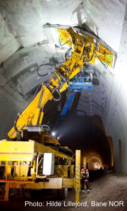
(a) Installation work
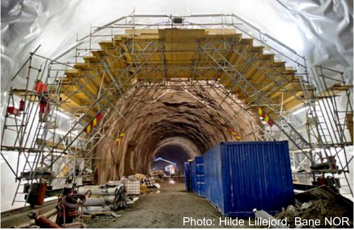
(b) Lining works
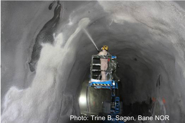
(c) Sprayed membrane
(d) Protected profile
4.2.10 Tunnel Safety
Tunnel safety is governed by the interaction between railway operations, evacuation possibilities, fire behaviour, and the technical systems installed in the tunnel.
4.2.10.1 Differences from Road Tunnels
Railway tunnel safety is fundamentally different from road tunnel safety. In railway tunnels:
-
Transport is guided by rails, so lateral deviation is not possible
-
All traffic is controlled by the signalling system (speed control, interlocking)
-
Strict fire protection regulations apply to rolling stock and installations
-
Human error is usually only one layer in a chain of technical, organisational and operational barriers, rather than a sufficient direct cause by itself
Risk modelling scenarios from road tunnels are therefore not directly applicable to railway tunnels.
4.2.10.2 Tunnel Safety Concepts
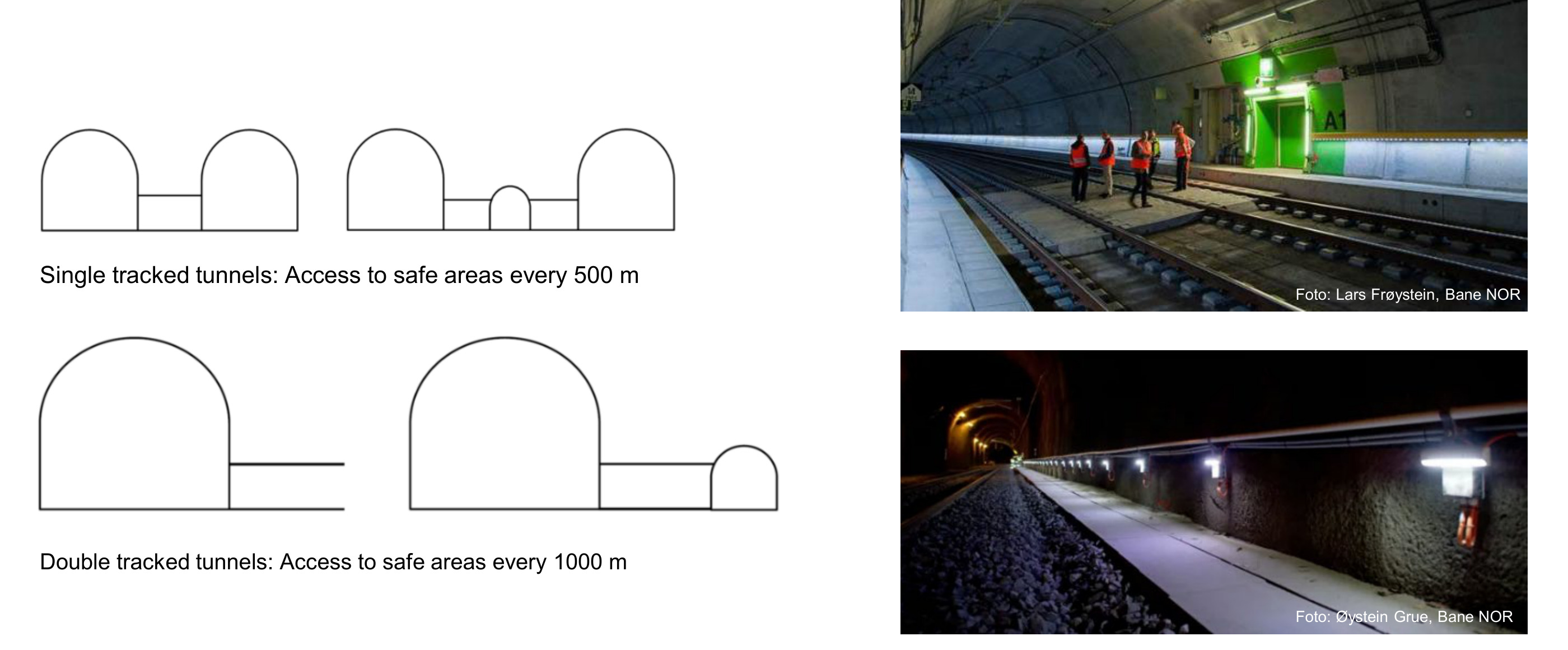
The EU Technical Specification for Interoperability: Safety in Railway Tunnels (TSI SRT) defines evacuation, safe-area and infrastructure requirements based on tunnel length, traffic concept and number of tracks. The summary below is an overview; the current TSI SRT and Bane NOR tunnel rules must be checked for a real design case. Figure 4.6 brings these safety concepts together by comparing the typical access arrangements for single-track and double-track tunnel concepts.
Key requirements from TSI SRT include:
-
Fire resistance of tunnel structures (all tunnels \(>100\) m)
-
Fire reaction of building materials (all tunnels \(>100\) m)
-
Fire detection in technical rooms (all tunnels)
-
Safe areas, cross-passages or emergency exits at prescribed spacing, depending on tunnel concept and length
-
Communication means in safe areas
-
Emergency lighting, emergency stop buttons, and telephone communication
Tunnel safety design therefore combines evacuation, fire resistance, lighting, communication, and drainage requirements, with applicability depending on tunnel length and layout.
| Requirement | Description | Single track | Double track |
|---|---|---|---|
| Fire resistance of structures | All structural elements | \(>100\) m | \(>100\) m |
| Fire reaction of materials | Reaction class of materials | \(>100\) m | \(>100\) m |
| Fire detection in technical rooms | Automatic detection systems | All | All |
| Emergency exits / safe areas | Exits every 500 m in single-track tunnels and 1000 m in double-track tunnels | \(>1000\) m | \(>1000\) m |
| Communication in safe areas | Emergency communication | \(>1000\) m | \(>1000\) m |
| Emergency lighting | Lighting in all areas | \(>500\) m | \(>500\) m |
| Emergency stop buttons | At platform areas | \(>1000\) m | \(>1000\) m |
| Telephone communication | At safe areas and cross-passages | \(>1000\) m | \(>1000\) m |
| Traction power disconnection | Remote disconnection means | \(>5000\) m | \(>5000\) m |
| Piston effect ventilation | Aerodynamic ventilation control | \(>1000\) m | \(>1000\) m |
| Smoke extraction ventilation | Active smoke control | \(>1000\) m | \(>1000\) m |
4.3 Cuttings
Cuttings are open excavations, but they share many design concerns with tunnels: stability, drainage, frost protection, and protection against falling material.
4.3.1 Definition and Functional Requirements
A railway cutting (skjæring) is an excavation through elevated or sloping terrain to maintain the required alignment and gradient. Like tunnels, cuttings are civil structures that must be properly designed. For visual orientation, examples of soil cuttings are shown later in Figures 4.7 and 4.8.
Functional requirements for cuttings include:
-
Allow the railway line to pass through elevated or slanting terrain in a cost-effective way
-
Protect the environment from railway traffic
-
Safety: stable slopes, safe for trains and passengers, including in winter conditions when snow drift build-up or ice formation is a risk
-
Reliability: reliable for traffic operation throughout changing seasons
-
Maintainability: low-maintenance design
4.3.2 Where Slopes Occur in Railways
Slopes and cuttings are encountered in several locations along a railway alignment:
-
Embankment fills: built to elevate the track over depressions or low terrain; embankment behaviour and failure modes are illustrated in Figures 4.11 and 4.15
-
Cut slopes: excavated through hills, ridges, or rock masses; soil and rock cutting examples are shown in Figures 4.7, 4.8, and 4.9
-
Sidehill cut-fills: a combination of excavation and fill on sloping terrain, combining the cutting and embankment situations illustrated in the figures above
-
River valleys: require alternating fills and cut-fills due to meandering rivers, often with repeated transitions between the situations shown in the cutting and embankment figures
4.3.3 Cuttings in Soil
Soil cuttings require careful design because the material properties determine the permissible slope inclination. Table 4.3 gives recommended maximum slopes for different granular material types under dry conditions. These are indicative values for preliminary assessment; final design must check groundwater, erosion, cutting height, construction stage, and long-term stability according to Eurocode 7 and Bane NOR's understructure requirements [7].
| Material type | Maximum slope (H:V) |
|---|---|
| Stone | 1:1.25 |
| Gravel, coarse sand | 1:1.5 |
| Fine sand, silt (dry) | 1:2 |
| Stratified / water-saturated | Evaluate separately |
| Clay | 1:2 |
In fine-grained, clayey soils, long-term stability is a particular concern. Immediately after excavation, the offloading causes negative pore pressures (suction), which temporarily increases effective stress and friction angle, thereby ensuring initial stability. However, over time this suction dissipates (pore pressures equalise), effective stress decreases, and the available shear strength falls. This means a cutting in clay that appears stable immediately after construction may become unstable months or years later. This is particularly important after heavy rainfall or snowmelt.
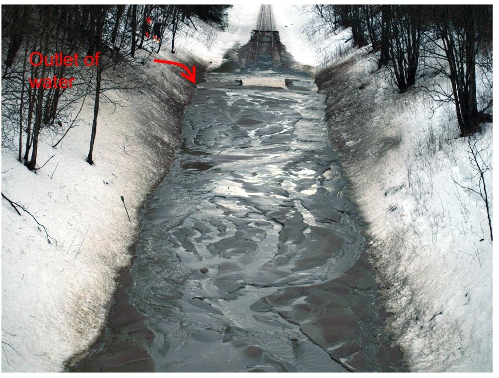
The failure at Valla on the Nordland line on 25 February 2008 illustrates the risk of instability in highly erodible soils. Saturation of fine-grained material behind a soil crust led to a rapid slope failure. The incident underscores the importance of proper drainage design in soil cuttings; the Valla failure in Figure 4.7 is a concrete example of this type of instability.
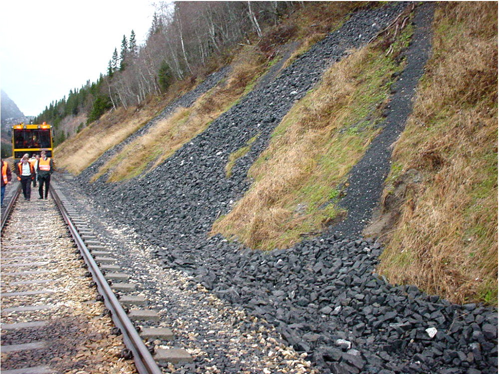
In such situations, drainage measures, for example diagonal drainage ditches (diagonale grøfter) on the cutting slopes, can significantly increase stability by reducing pore pressures within the slope. Diagonal ditches are more effective than straight horizontal ditches because they intercept a larger portion of the groundwater flowing through the slope; Figure 4.8 shows this measure in an existing soil cutting.
4.3.4 Cuttings in Rock
Rock cuttings require a stability assessment, much as for tunnel design. Key design considerations include:
-
High rock cuttings (more than approximately 20 m) should be avoided; a tunnel may be preferable
-
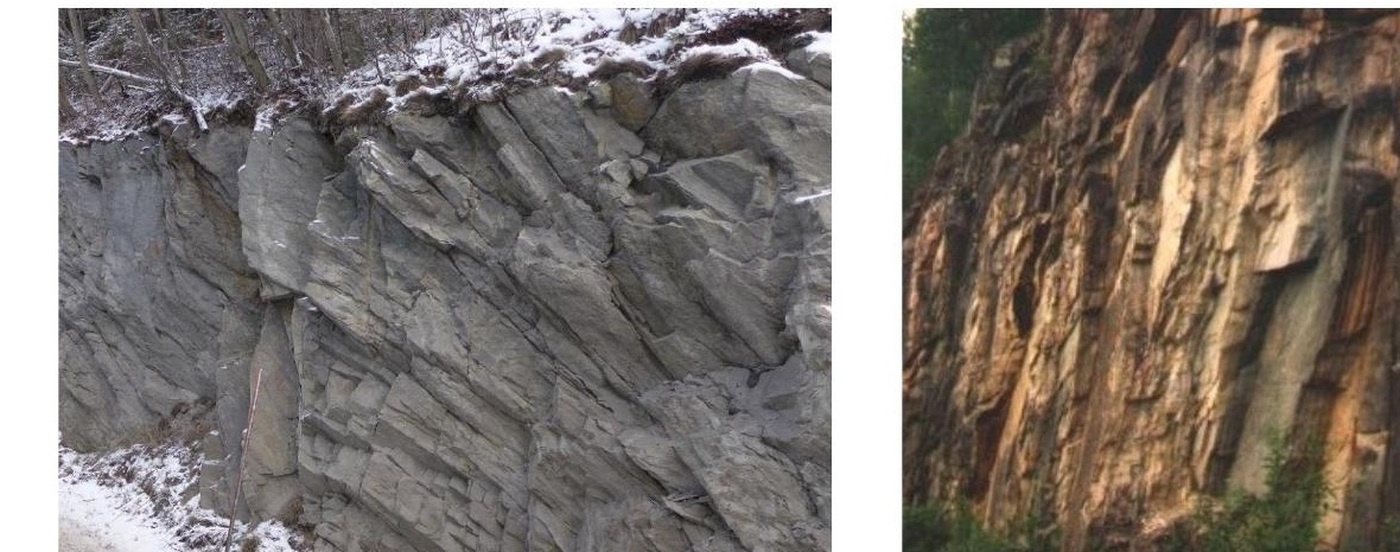
The orientation of discontinuities, joint sets, bedding, and foliation is decisive for slope stability and must be mapped by an engineering geologist
-
Steep slopes minimise excavated volume but require careful assessment
-
Ditches must safely collect minor stones and block larger ones (bolting required for large unstable blocks)
-
Ice build-up during winter must be addressed in the ditch design
The discontinuity patterns sketched in Figure 4.9 are typical of the geometrical checks needed before a rock cutting slope can be accepted.
4.3.4.1 Rock Fall Ditch Design
A key safety element in rock cuttings is the rock-fall catch ditch (fanggrøft) at the base of the cutting slope. The ditch is not designed from a single rock trajectory; it is a geometric safety zone between the track and the rock face. Its width \(E\) and depth \(D\) are selected from the cutting height \(H\) and slope angle \(\alpha\) so that falling blocks are intercepted before they can reach the track area [7]. The design geometry is defined in Figure 4.10, and the corresponding recommended dimensions are given in Table 4.4.
.](../../assets/chapters/ch04/original/figures_lecture_crops/fig_rockfall_ditch_lecture.png)
| Slope angle | Height \(H\) (m) | Width \(E\) (m) | Depth \(D\) (m) |
|---|---|---|---|
| Vertical, ca. \(80\text{--}90^\circ\) | 5–10 | 3.0 | 1.0 |
| 10–20 | 5.0 | 1.5 | |
| \(>20\) | 6.5 | 1.5 | |
| \(4{:}1\) to \(3{:}1\), ca. \(75^\circ\) | 5–10 | 3.0 | 1.0 |
| 10–20 | 5.0 | 1.5 | |
| 20–35 | 6.5 | 2.0 | |
| \(>35\) | 8.0 | 2.0 | |
| \(2{:}1\), ca. \(65^\circ\) | 5–10 | 3.0 | 1.0 |
| 10–20 | 5.0 | 2.0 | |
| 20–35 | 6.5 | 2.0 | |
| \(>35\) | 8.0 | 3.0 | |
| \(4{:}3\), ca. \(55^\circ\) | 0–10 | 3.0 | 1.0 |
| 10–20 | 3.0 | 1.5 | |
| \(>20\) | 5.0 | 2.0 | |
| \(1{:}1\), ca. \(45^\circ\) | 0–10 | 3.0 | 1.0 |
| 10–20 | 3.0 | 1.5 | |
| \(>20\) | 5.0 | 2.0 |
4.4 Embankments
Embankments raise the track above existing ground and therefore introduce settlement, bearing capacity, drainage, and slope-stability checks.
4.4.1 Definition and Vulnerability
A railway embankment (fylling) is a raised earthwork structure that carries the track above the surrounding terrain. Embankments are among the most common substructure elements on the Norwegian network and can be vulnerable to both settlement and slope instability.
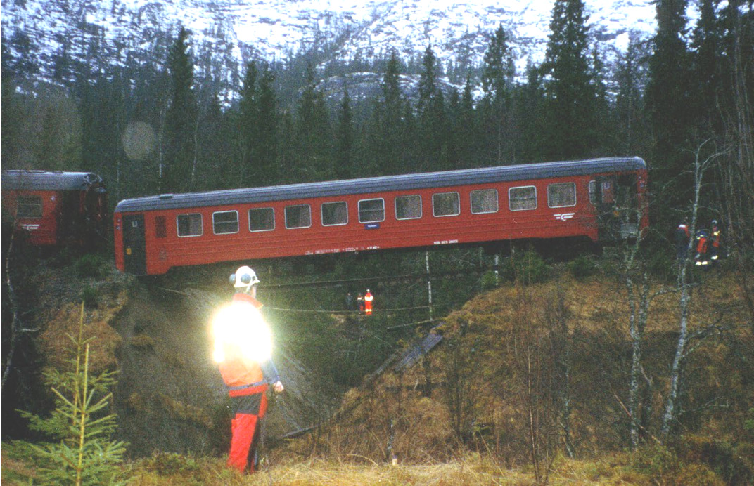
A severe embankment failure occurred on the Nordland line on 17 December 1998 (Figure 4.11). Such events highlight the need for systematic geotechnical design and risk management for all embankments [122, 124].
4.4.2 Material Selection
Material selection for railway embankments is governed by erosion resistance and shear strength: coarse granular materials are normally preferred, while organic soils and weak fine-grained materials require treatment or replacement.
| Material type | Erosion resistance | Embankment strength |
|---|---|---|
| Rockfill | Excellent | Excellent |
| Gravel, well to poorly graded | Excellent–Good | Good |
| Sand, well to poorly graded | Good–Fair | Good |
| Clays of low plasticity, sandy clays | Good with moisture control | Conditional |
| Clays of high plasticity | Poor | Conditional / treatment required |
| Organic soils, peat | Unsuitable | Unsuitable |
Preliminary side slopes depend on the same material behaviour; they are only starting values before groundwater, height, frost and stability calculations are checked.
| Material type | Typical minimum side slope (H:V) |
|---|---|
| Rockfill | 1.5:1 |
| Sand and gravel | 1.8:1 |
| Sand | 2:1 |
| Fine-grained clay/silt | 2.5:1 to 3:1 |
Compaction requirements must be specified for each embankment. The degree of compaction achievable is material-dependent: granular materials compact well under vibratory rollers, while cohesive materials require sheepsfoot or pneumatic-tyred rollers [122, 141].
4.4.3 Settlements
Settlement is a reduction in the elevation of the embankment and underlying soil due to loading. Settlement in soft soils is one of the most significant operational challenges on low-lying sections of the Norwegian network.
4.4.3.1 Types of Settlement
Settlement mechanisms are separated by when they occur and by whether deformation is recoverable, consolidating, or creep-related:
-
Initial (elastic) settlement: occurs immediately during construction due to elastic deformation of the soil
-
Primary settlement (consolidation): occurs over time as excess pore water drains from the soil, reducing volume. This is often the dominant settlement type in clay and silt.
-
Secondary settlement (creep): occurs under constant effective stress after primary consolidation is complete. Rate is approximately proportional to \(\log(t)\) and continues indefinitely.
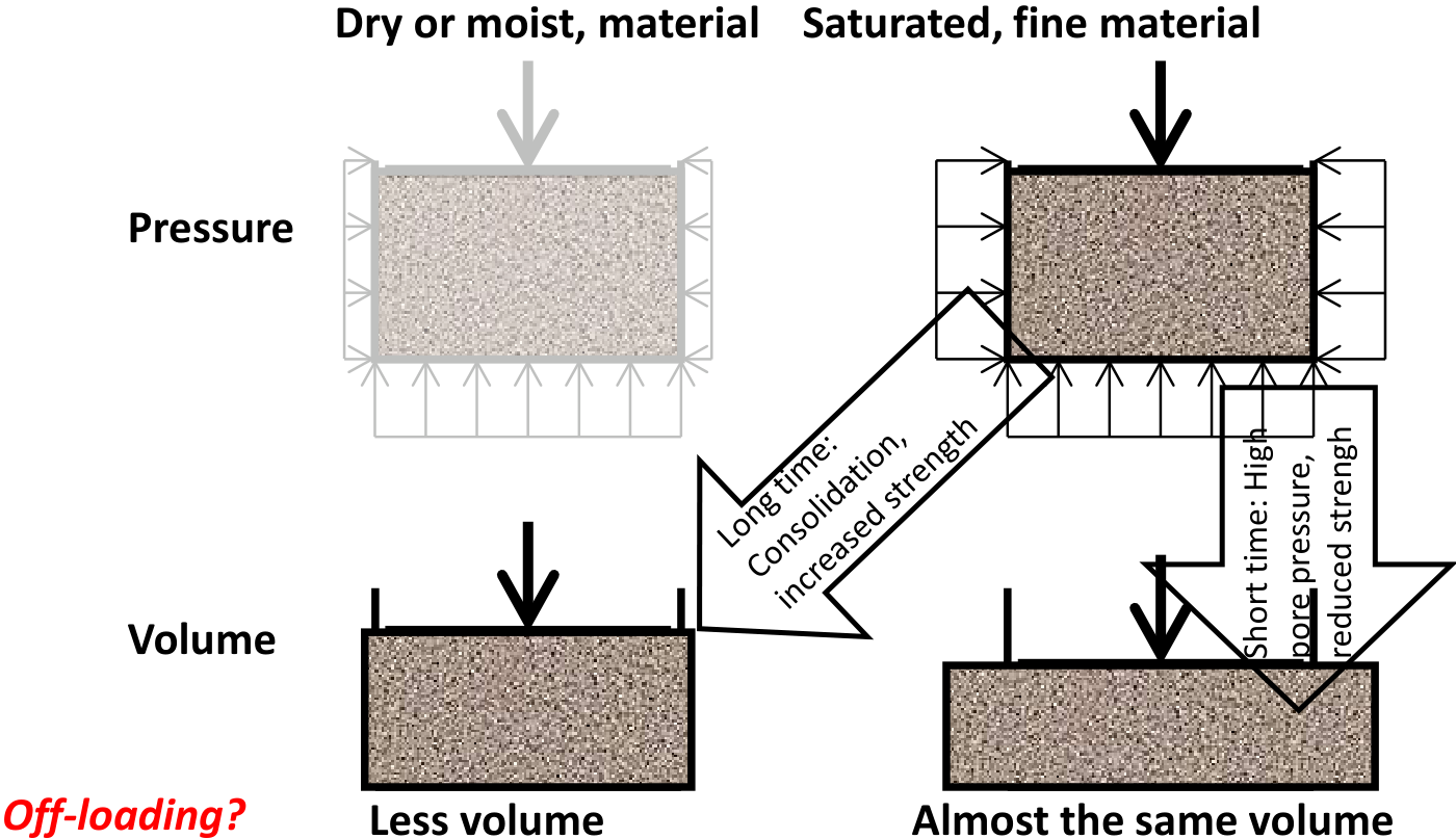
Figure 4.12 helps explain why saturated fine-grained soils behave differently from dry or moist granular materials: pore pressure initially carries part of the load, and settlement develops as water drains.
The rate of primary consolidation depends on the drainage distance (typically half the layer thickness) and the permeability of the soil. For thick, low-permeability clay layers, consolidation may take decades.
4.4.3.2 Critical Settlement Factors
Even uniform long-term settlements are generally not a problem for the track itself, but they can be corrected by tamping. The critical factors are:
-
Differential settlements along the track: create vertical alignment irregularities (track geometry defects) that directly affect ride quality and safety
-
Differential settlements across the track: can affect cant (superelevation), creating cross-level defects
-
Transition zones: where ground conditions change abruptly, for example from embankment to rock cutting, or from soft ground to a bridge abutment. These are the most problematic locations because the stiffness transition causes dynamic amplification.
-
Effects on structures: overhead line masts, bridges, and other structures founded on settling soils
These mechanisms later appear as subgrade and embankment defects in Chapter 15, and as measured longitudinal level, cross-level and twist problems in Chapter 16.
4.4.3.3 Settlement Reduction Measures
Several methods are used to reduce settlement:
General methods
-
Reduce the applied load (lower embankment height, use lightweight fill materials)
-
Increase the soil stiffness (soil replacement, lime-cement pile treatment)
-
Smooth the differential settlement profile (gradually varying embankment thickness, soil reinforcement with geogrids)
-
Accelerate settlement before track opening (preloading, vertical drains)
Lightweight fill materials
Expanded clay aggregates (LECA) and foam glass (skumglass) are used to reduce embankment weight. This provides a double benefit: reduced settlement and improved slope stability (lower driving load). Expanded polystyrene (EPS) blocks are also used in selected cases.
Piled embankment
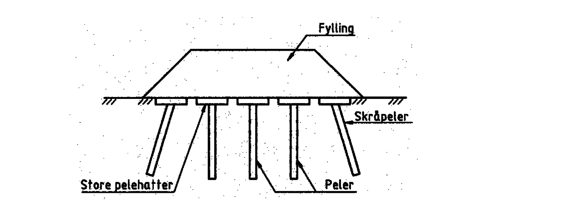
A piled embankment transfers embankment loads to piles driven to a firm stratum, bypassing the compressible soft layer. Load distribution from embankment to pile caps is achieved through synthetic geogrids. This is a costly solution but may be cost-effective compared to constructing a bridge.
Figure 4.13 presents the load-transfer concept: the embankment load is spread through the fill and geogrid system before being carried by piles into a firmer bearing layer.
Preloading and wick drains
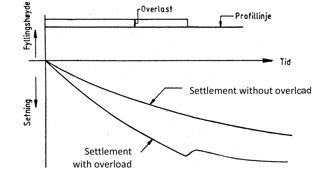
The embankment is built temporarily to a greater height than its final design level (overloading). Prefabricated vertical drains (wick drains) are installed in the soft layer to accelerate pore water drainage. This speeds up primary consolidation so that most settlement occurs during construction, before the track is laid. Once the target settlement has been achieved, the excess fill is removed and the track laid on the consolidated, stronger soil.
The settlement-time sketch in Figure 4.14 shows why this can be effective: the temporary overload forces much of the settlement to occur before the line is opened to traffic.
4.5 Slope Stability
The previous substructure types all depend on slope stability. This section gathers the basic safety check used to assess whether soil and rock masses can resist failure.
4.5.1 Basic Concepts
Slope stability is assessed by the partial factor against landslide \(\gamma_m\):
where \(\tau_k\) is the characteristic (maximum) shear strength (capacity) and \(\tau\) is the calculated shear stress (demand). The slope is considered stable when \(\gamma_m > 1\) and unstable when \(\gamma_m < 1\). Typical required values are \(\gamma_m = 1.3\)–\(1.6\).
Simple example.
If a potential slip surface has available shear strength \(\tau_k=80\) kPa and calculated shear stress \(\tau=50\) kPa, then \(\gamma_m=80/50=1.60\). If the required partial factor is 1.4, the slope passes because \(1.60>1.4\). If the shear stress increases to 65 kPa, then \(\gamma_m=80/65=1.23\), so the same slope would fail the requirement.
4.5.2 Required Partial Factors in the Technical Regulations
Bane NOR technical regulations specify minimum partial factors for stability analyses as a function of the consequence of failure, the mechanism of failure (brittle or ductile), and the method of analysis [7]:
Higher consequence classes and brittle failure mechanisms require larger partial factors, so the selected analysis method directly affects the design margin.
| Analysis method | Consequence of failure | Ductile | Neutral | Brittle |
|---|---|---|---|---|
| Effective stress analysis, \(a\phi\)-method | Less serious | 1.25 | 1.30 | 1.40 |
| Serious | 1.30 | 1.40 | 1.50 | |
| Very serious | 1.40 | 1.50 | 1.60 | |
| Total stress analysis, ADP-method | CC1 less serious | 1.40 | 1.40 | 1.40 |
| CC2 serious | 1.40 | 1.40 | 1.50 | |
| CC3 very serious | 1.40 | 1.50 | 1.60 |
For effective stress (drained) analysis using the \(a\phi\)-method, required partial factors range from 1.25 (less serious, ductile) to 1.60 (very serious, brittle failure). For total stress (undrained) analysis using the ADP-method, factors range from 1.40 to 1.60. Additional regulations are set by the Norwegian Water Resources and Energy Directorate (NVE) and the National Public Roads Administration.
4.5.3 Bearing Capacity of Soft Subsoil
When an embankment is constructed on soft clay, the foundation may fail by overall shear before excessive settlement even occurs. The undrained bearing capacity (Skempton's formula for a strip footing, which is a conservative and widely used approximation for railway embankments) is:
where \(q_f\) is the foundation failure pressure [kPa], \(c_u\) is the undrained shear strength of the soft layer [kPa], and \(N_c\) is the bearing capacity factor. For a surface strip footing on a homogeneous undrained clay, Prandtl's solution gives \(N_c = \pi + 2 \approx 5.14\). Skempton (1951) provided depth and shape corrections, but \(N_c = 5.14\) is standard for a conservative analysis of long embankments.
The applied foundation pressure from the embankment:
where \(\gamma_\mathrm{fill}\) is the unit weight of fill [kN/m\(^3\)] and \(H\) is the embankment height [m].
For this simplified bearing-capacity screening, define the available bearing-capacity ratio:
This is a first-screening ratio, not a separate regulatory symbol. It is compared with the required ADP-method material partial factor \(\gamma_m\) from Table 4.7; for example, a serious consequence, neutral failure mechanism requires \(\gamma_m=1.40\).
Worked example.
Consider a 4.0 m high railway embankment on soft clay with undrained shear strength \(c_u = 28\) kPa. The fill unit weight is \(\gamma_\mathrm{fill}=19\) kN/m\(^3\), and a first screening is made with the simplified uniform embankment pressure:
For the simplified check, \(F_\mathrm{bc}=1.89\) is higher than the required \(\gamma_m=1.40\), so the embankment passes the initial undrained bearing-capacity screening. The available height for the same soil strength and fill density can also be estimated by rearranging Eq. 4.4:
This means that a 4.0 m embankment has a clear margin in this first-screening calculation. A detailed design must still include traffic surcharge, staged construction, pore-pressure development, settlement, and global slope stability.
4.5.4 When to Assess Stability
Stability must be assessed for all of the following:
-
Embankments, both in flat and slanting terrain
-
Soil cuttings and rock cuttings
-
Natural slopes in the vicinity of new construction
-
Foundations for structures and bridges
-
Retaining walls and slopes with soil reinforcement
Stability must also be re-assessed for existing lines if construction work is carried out nearby, if river bank erosion occurs, or if excavated material is placed on slopes (e.g., from ditch clearing or ballast cleaning).
4.5.5 Loads for Stability Calculations
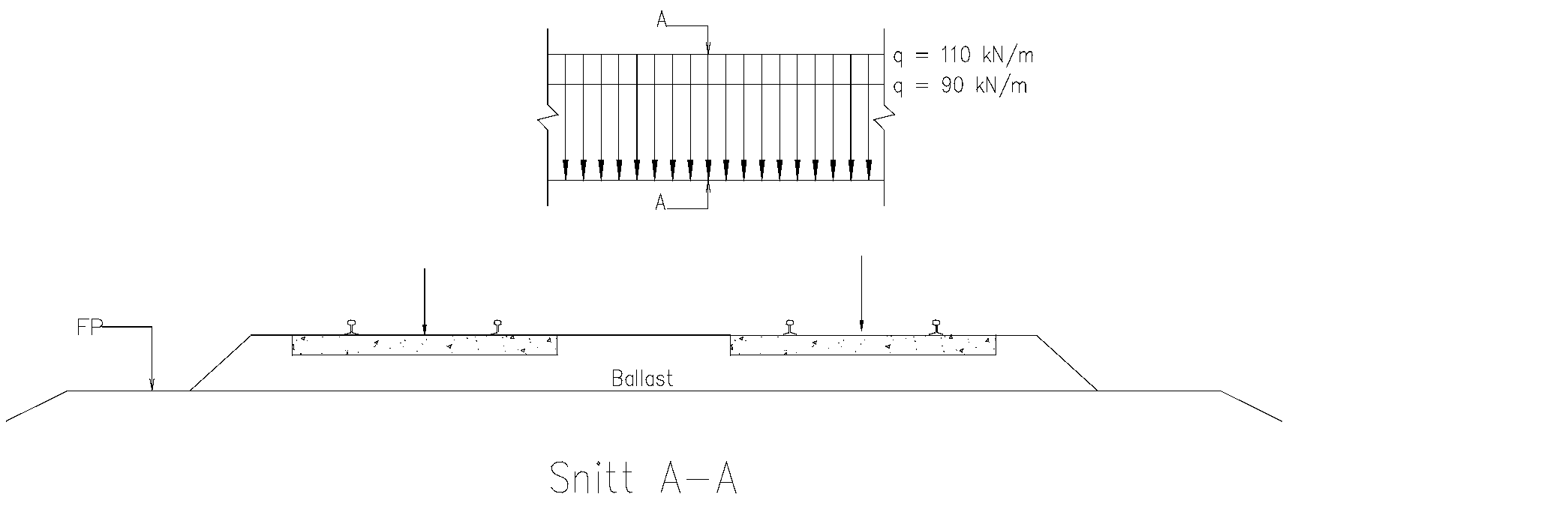
The standard load configuration for stability analysis of railway embankments accounts for the track structure and train loading. Bane NOR defines standard load intensities for single-track and double-track configurations for slope-stability assessment; these loads should not be confused with detailed bridge or vehicle–track dynamic load models. Figure 4.15 separates the single-track and double-track load cases used for these geotechnical checks.

(a) Single-track load configuration
(b) Double-track load configuration
4.5.6 Quick Clay
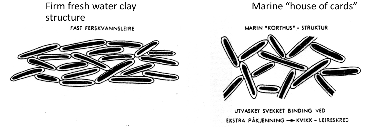
Quick clay (kvikkleire) is a particular hazard in Scandinavia. It is a marine clay whose internal structure collapses upon remoulding, causing a dramatic reduction in shear strength from its original value to a remoulded value sometimes below 0.5 kPa [122]. Failure in quick clay is brittle and can progress rapidly, involving much larger volumes of soil than the initial slip. Quick clay deposits must be identified from geological maps and site investigations. For undrained analyses in anisotropic soft or quick clay, the ADP total-stress method with appropriate consequence-class partial factors is normally used. The Nesvatnet landslide in Figure 4.16 shows the kind of large infrastructure consequence that quick-clay terrain can produce. The structural contrast in Figure 4.17 explains why quick clay can lose strength so abruptly when remoulded.
![Quick-clay landslide at Nesvatnet, Levanger, 30 August 2025. The slide damaged both the E6 highway and the railway corridor. Photo: Ole Martin Wold/NTB, reproduced from NGI [131].](../../assets/chapters/ch04/original/figures_web/fig_nesvatnet_quick_clay_levanger_2025.jpg)
4.5.7 Stabilising Measures
For quick-clay and slope-stability problems, stabilising measures either improve soil strength, reduce driving shear stress, or transfer load to a stronger stratum:
-
Improving soil strength: lime-cement treatment (kalksementpaler), drainage to reduce pore pressures, soil replacement
-
Reducing shear stress: reduce slope angle, remove material from the driving zone, reduce cut depth, install berms at the toe of the slope
-
Transferring load to stronger stratum: sheet piles (spunt), retaining walls, piles, or rock bolts
It is important to note that stabilising measures that reduce shear deformations do not necessarily reduce settlements:
-
Removing material reduces settlements (lower vertical load)
-
Adding material such as berms increases settlements (higher vertical load)
-
Lime-cement treatment has varying effects, but the additional drainage effect increases the speed of consolidation
4.6 Components of the Track Substructure
The complete substructure cross-section typically comprises the following layers from the ground surface upward:
-
Natural ground / subgrade [122, 65]: the in-situ material after excavation or below the embankment; must meet bearing capacity and settlement requirements
-
Embankment body / fill: compacted granular or cohesive fill to achieve the required track level
-
Subballast / formation layers: one or more layers of crushed rock or graded aggregate that provide frost protection, drainage, and a stable platform for ballast; in technical regulations terminology referred to as the underbygning layers
-
Formation plane (planum): the top of the substructure; the interface with the ballast bed; defined at a specific level relative to the top of rail (TOR) as discussed in Chapter 3
4.6.1 Frost Protection
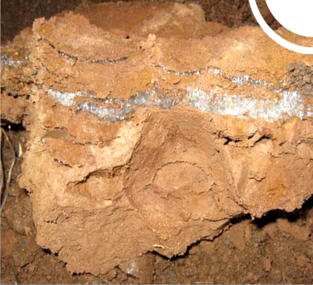
The Norwegian climate imposes strict frost protection requirements on the substructure [7, 122]. The formation plane level must be set deep enough that frost penetration does not reach frost-susceptible materials (clay, silt). the technical regulations specify frost protection design based on the climatic frost index for each region, the thermal properties of the substructure layers, and the traffic load. Typical subballast and formation layer thicknesses on the Norwegian network range from 0.4 m to over 1.0 m depending on the frost exposure zone. Frost susceptibility is screened from soil type and grain-size distribution; the technical regulation classification links the soil class to the expected frost-heave risk. Silts and silty moraines are often critical because they combine capillary water supply with enough permeability to feed the freezing front, whereas very fine clays may have high capillary rise but slower water movement. The ice lenses in Figure 4.18 show the mechanism that frost protection is intended to prevent.
| Class | Frost susceptibility | \(<0.02\) mm | \(<0.2\) mm | Typical soils |
|---|---|---|---|---|
| T1 | Not frost-susceptible | \(\leq 3\,\%\) | N/A | Sand, gravel, peat and organic soil |
| T2 | Slightly frost-susceptible | \(>3\)–\(\leq 12\,\%\) | N/A | Sand, gravel, sandy or gravelly moraine |
| T3 | Moderately frost-susceptible | \(>12\,\%\) | \(<50\,\%\) | Sand, clayey moraine, clay with more than 40 % clay-size particles |
| T4 | Highly frost-susceptible | \(>12\,\%\) | \(>50\,\%\) | Silt, silty moraine, clay with less than 40 % clay-size particles |
4.6.2 Drainage
Effective drainage of the substructure is essential for [122, 7]:
-
Preventing pore pressure build-up that could trigger slope instability
-
Removing water from the ballast bed (longitudinal track drains)
-
Preventing frost heave by keeping frost-susceptible materials dry
-
Ensuring long-term drainage capacity throughout the service life of the track.
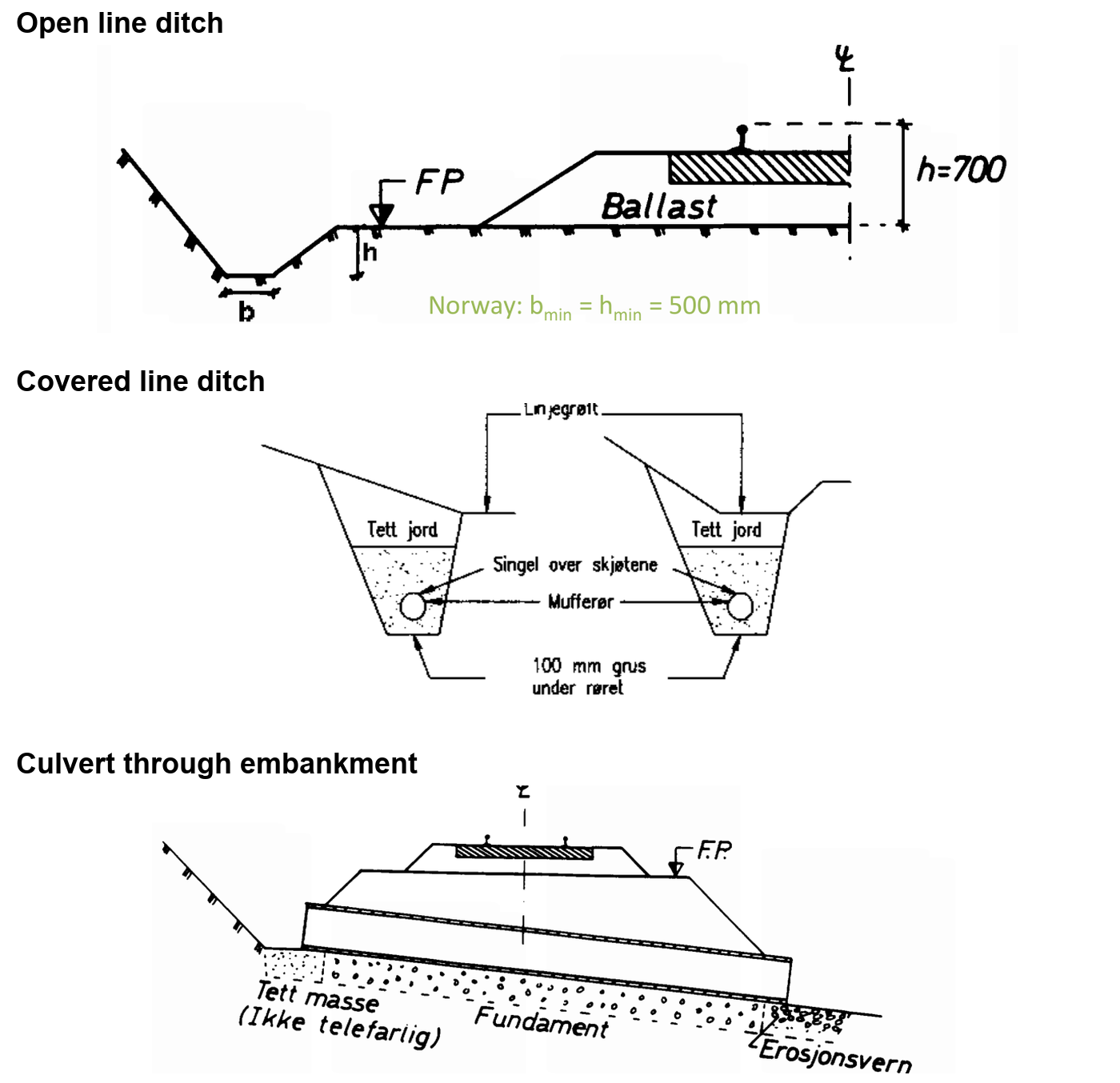
Drainage design on Norwegian railways follows Bane NOR technical regulations Underbygning/Prosjektering, which specifies minimum longitudinal track drain dimensions, catch pit spacing, and requirements for geotextile filters at the ballast–subgrade interface to prevent fines migration into the drain. Common drainage elements are gathered in Figure 4.19. For preliminary sizing of surface-water runoff, a rational-method estimate is often used:
where \(C\) is the runoff coefficient, \(i\) is the design rainfall intensity, and \(A\) is the catchment area. If \(i\) is given in \(\mathrm{L\,s^{-1}\,ha^{-1}}\) and \(A\) in \(\mathrm{ha}\), \(Q\) is obtained directly in \(\mathrm{L\,s^{-1}}\). The selected design storm and return period must reflect the consequence of flooding, local meteorological statistics, and the available discharge path.
Worked example.
Assume that two catchments drain towards the same railway ditch. An urban catchment has \(A=1.5\) ha, \(C=0.80\), and \(i=60\,\mathrm{L\,s^{-1}\,ha^{-1}}\). A forested catchment has \(A=4\) ha, \(C=0.25\), and \(i=45\,\mathrm{L\,s^{-1}\,ha^{-1}}\). The design runoff is:
If both catchments discharge to the same downstream ditch or culvert, the preliminary combined design flow is \(Q_\mathrm{tot}=72+45=117\,\mathrm{L\,s^{-1}}\) before applying any additional allowances required by the design rules. Although the urban catchment is smaller, it produces the larger runoff because the runoff coefficient and rainfall intensity are higher.
4.7 Chapter Summary
Foundation role. Rails, fastenings, sleepers and ballast can only perform well if the ground below them provides adequate stiffness, drainage and stability. The substructure includes formation, embankments, cuttings, slopes, tunnels, frost protection and drainage systems. These elements are less visible than the superstructure, but they often determine whether geometry deterioration is slow and manageable or rapid and recurrent.
Tunnels and cuttings. Tunnel design requires rock classification, support selection, drainage, frost protection and safety planning. Cuttings require similar attention to geology and water, because soil instability, rockfall and erosion can threaten both track safety and availability. The engineering task is not only to excavate the required profile, but to maintain a stable boundary around the railway throughout operation.
Embankments and slopes. Embankments transfer repeated train loads to the underlying ground and can be vulnerable to differential settlement, bearing-capacity failure and slope instability. Soft soils, quick clay, poor drainage and high groundwater levels increase risk and may require stabilisation, staged construction, lightweight fill, piles or other ground-improvement measures. Stability checks therefore combine soil strength, load effects, geometry and partial factors.
Water and frost. Poor drainage reduces soil strength, accelerates ballast fouling, increases frost susceptibility and creates maintenance problems that reappear after each correction. Frost heave and thaw weakening can damage geometry even when the track has adequate capacity under dry summer conditions. Drainage and frost protection must therefore be treated as structural requirements, not as secondary details added after the alignment is designed.
Long-term risk. Ground conditions are variable, and failures often develop gradually before becoming operationally critical. Robust design combines investigations, classification, calculation, monitoring and maintenance access. The best substructure solution is one that limits deformation, controls water, provides sufficient stability and remains inspectable and repairable under railway operating constraints.
Assignments
Assignment 1: Embankment bearing capacity and stability
An embankment carries a double-track railway at a height of 5 m above the original ground level. The embankment is built on a soft clay subgrade with undrained shear strength \(c_u = 30\) kPa. The embankment fill has unit weight \(\gamma = 20\) kN/m\(^3\); the embankment slopes are 1:2 (vertical:horizontal).
(a) Estimate the contact stress at the base of the embankment using the simplified uniform load model.
(b) Check whether the bearing capacity of the subgrade is adequate using the simple undrained bearing capacity formula \(q_{\mathrm{ult}} = 5.14\,c_u\).
(c) For a total-stress (ADP-method) stability analysis, the technical regulations require a material partial factor of at least \(\gamma_m = 1.40\). Explain what this factor means in practice, and why a passed bearing-capacity check is not by itself enough to approve the embankment.
Assignment 2: Quick clay hazard and stabilisation
A soil investigation for a new railway line in the Oslo region reveals a clay layer with remoulded shear strength \(s_r = 0.4\) kPa at a depth of 4 m below the embankment base.
(a) Identify the type of clay and explain why it poses a particular hazard for railway construction.
(b) Describe two stabilisation measures appropriate for this situation.
(c) Explain why performing a standard slope stability calculation without recognising the quick clay hazard could lead to a dangerously unconservative result.
Assignment 3: Frost protection for high-speed track
A section of track in a region with a design frost index \(I_F = 60{,}000\,\mathrm{h}\!\cdot\!{}^\circ\mathrm{C}\) is to be upgraded to allow 250 km/h operation. The existing subballast depth is 250 mm, and the subgrade contains silty material that may be frost-susceptible.
(a) Explain the purpose of the frost protection layer and why its required depth is speed-dependent.
(b) State qualitatively how the required frost depth relates to the design frost index, water availability, and the thermal properties of the substructure materials.
(c) Explain why silts are often more frost-heave critical than very fine clays, even though clays can have high capillary rise.
(d) Describe how the Norwegian frost-susceptibility classes T1–T4 are used in design, and identify which end of the scale is most critical.
(e) If the existing subballast does not meet the frost protection requirement, describe two design options for bringing the track into compliance.
Assignment 4: Drainage catchment runoff
A railway line passes through two catchments that discharge towards the track drainage system. In the first catchment, an urban area of 2 ha has runoff coefficient \(C=0.85\) and design rainfall intensity \(i=70\,\mathrm{L\,s^{-1}\,ha^{-1}}\). In the second catchment, a forested area of 5 ha has runoff coefficient \(C=0.30\) and design rainfall intensity \(i=50\,\mathrm{L\,s^{-1}\,ha^{-1}}\).
(a) Describe the primary purposes of railway drainage, and give examples of what can happen if drainage stops working properly.
(b) List the main drainage elements used in railway substructures and explain when each is used: terrain ditches, slope ditches, open or covered line ditches, and culverts.
(c) Use \(Q=C\,i\,A\) to calculate the design runoff from each catchment.
(d) Compare the two results and explain why catchment area alone is not enough to judge drainage demand.
(e) Explain why the selected design storm, return period, and meteorological statistics matter for culvert and ditch design.
Assignment 5: Cutting slope stability warning signs
A cutting on an existing single-track line passes through a hillside of glacial till overlying marine clay. Recent ditch-clearing work has removed material from the cutting slope, and a small tension crack has appeared at the top of the slope.
(a) Identify the signs that a stability assessment is urgently required.
(b) Describe the investigation steps that Bane NOR would require before deciding on a remedial measure.
(c) Discuss the implications for slope stability of removing material from the upper (driving) zone versus adding a berm at the toe of the slope, with reference to the respective effects on driving shear stress and resisting moment.
(d) Explain why the presence of a marine clay layer in the cutting face increases the risk of progressive failure, and what factor is used to account for this in the ADP stability calculation.