Track Damage and Defects
15.1 Introduction
Track damage and defects are the unavoidable consequence of subjecting a mechanically complex system to millions of repeated high-magnitude load cycles. Understanding the mechanisms, appearance, and consequences of track defects is fundamental to railway engineering: it underpins inspection planning, maintenance scheduling, and the design choices that minimise damage accumulation [65, 124].
Defects are categorised by their location in the track structure (rail, sleeper, fastening, ballast, subgrade) and by the mechanism causing them (contact fatigue, bending fatigue, wear, corrosion, environmental loading). A defect that is merely an inconvenience in one location may be a safety-critical failure mode in another: a surface scratch on the rail head is of no consequence, whereas a transverse crack at the same depth below the surface can lead to sudden rail fracture.
This chapter describes the most important defect types for each track component, their causes, detection methods, and maintenance responses. Rail surface and internal defects receive the most attention because they carry the highest safety risk.
15.2 Rail Surface Defects
Rail surface defects occur on the running surface and gauge face of the rail head. They are initiated by concentrated contact stresses at the wheel–rail interface; Chapter 1 gives the preliminary stress chain, while Chapter 8 explains the local contact mechanics. The defects then propagate by the combined action of contact stress cycling, thermal loading, and corrosion.
15.2.1 Rolling Contact Fatigue
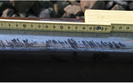
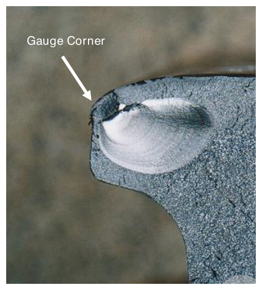
Head checks (kjørekantsprekker) are fine surface-initiated RCF cracks on the gauge corner of the rail head. They appear as closely spaced, oblique-to-transverse cracks, typically at 1–10 mm spacing, and are most common on the outer rail in curves where flange-root contact gives high tangential stress. Shallow head checks are usually treated by corrective rail grinding; deeper cracks may require local rail replacement or traffic restrictions. If the cracks turn downward, they can become transverse cracks and eventually cause rail fracture [36]. Figure 15.1 shows the repeated shallow cracks on the gauge corner.
Squats are dark, kidney-shaped RCF defects on the crown of the rail head, as shown in Figure 15.2. They often start at a local stress concentration, surface pit, or material irregularity and develop into a depressed patch with branching cracks around its rim. They are detected visually, by the sound of wheel impact, and by automated geometry measurement when the local depression affects longitudinal level.
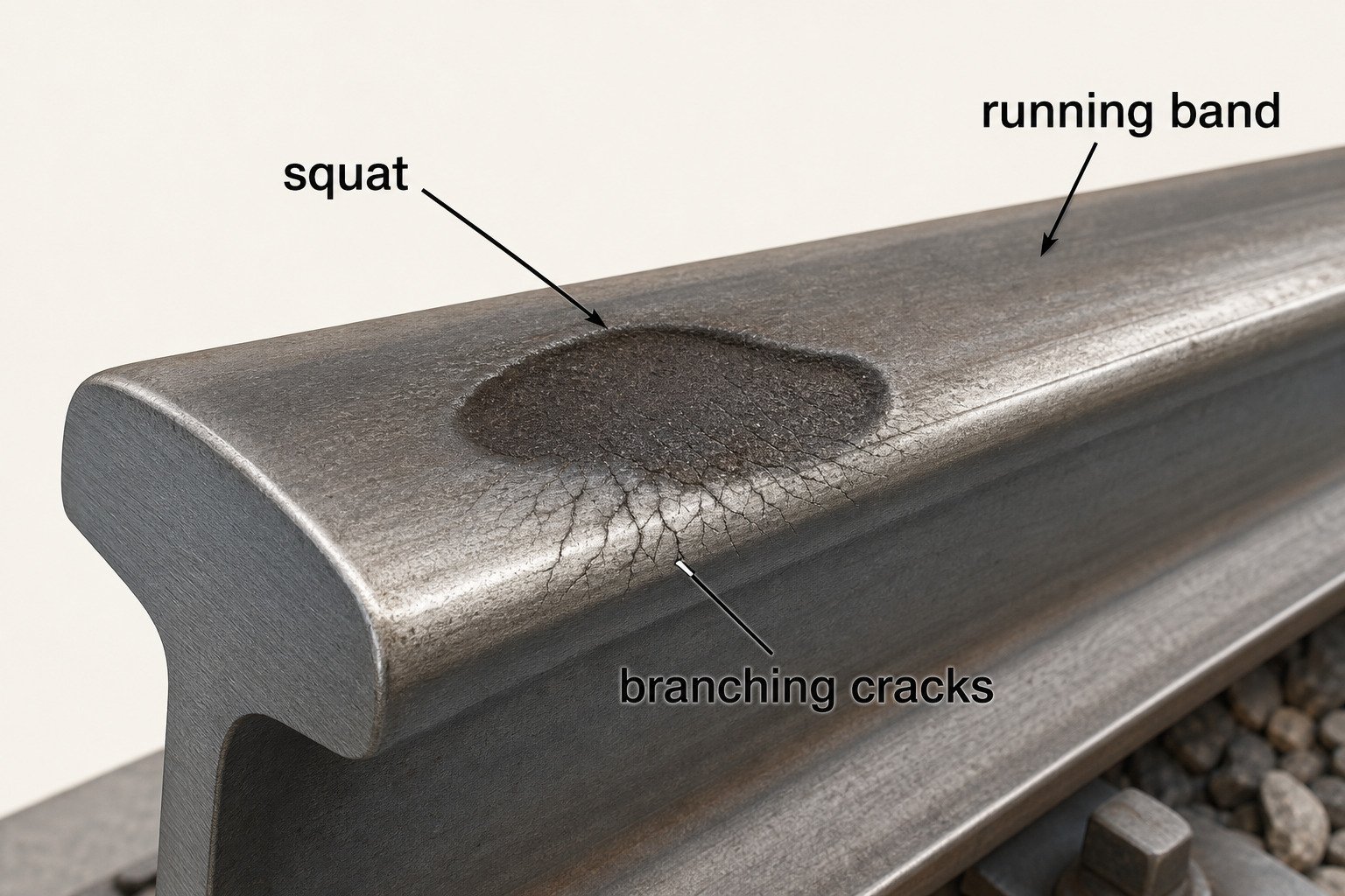
Bane NOR records squats as UIC defect code 227, sprekker og lokale nedsenkninger på kjøreflaten. The response is based on fracture condition and ultrasonic indication, not on an A–B–C surface-size class. The ultrasonic limits below describe signal size: an equivalent flat-bottom-hole reflector size is used for crack amplitude, while full-screen height refers to the echo height on the ultrasonic display.
| Condition | Group | Required response |
|---|---|---|
| Rail already broken | 0 | Remove the defect immediately and introduce traffic restrictions. |
| Large ultrasonic indication: equivalent flat-bottom-hole reflector size \(> 10\) mm, or at least two indications \(\geq 40\%\) full-screen height within three sleepers | 1 | Remove the defect as soon as possible. |
| Medium ultrasonic indication: equivalent flat-bottom-hole reflector size \(\geq 5\) mm and \(< 10\) mm | 2a | Remove the defect. |
| No recordable transverse crack | 2b | Keep the rail under observation. |
Shallow squat cracks may be removed by reprofiling, by grinding or milling, if the crack depth is still within the removable rail-head material; Bane NOR gives a typical maximum of 4–8 mm depending on rail profile and wear condition [36].
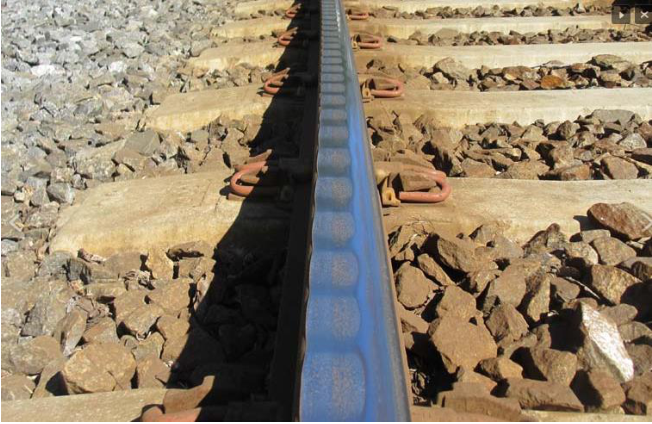
Corrugation (rifler) is the periodic light–dark banding visible on the running surface in Figure 15.3. It is a short-wavelength waviness rather than a crack defect. Corrugation is driven by wheel–rail dynamic interaction and wear; it increases noise and vibration and is removed by rail grinding [101, 102, 124].
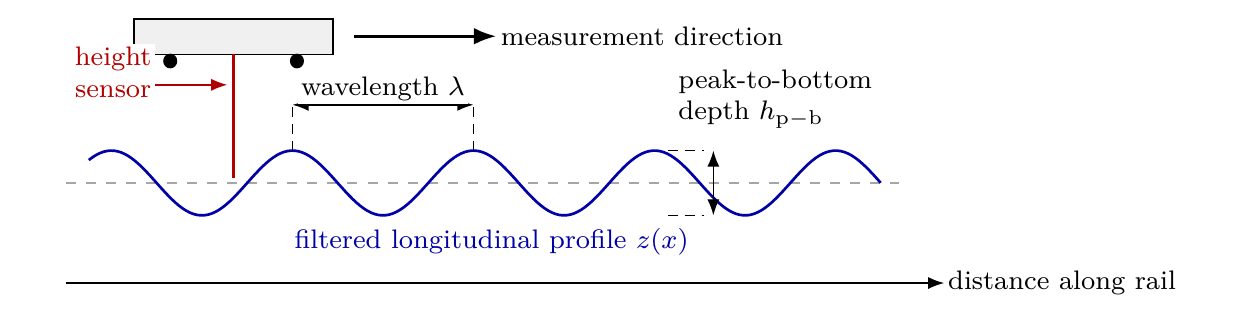
Corrugation is measured from the longitudinal profile of the rail running surface, not from the colour contrast alone. A measuring trolley or vehicle-mounted roughness system records the rail-head height \(z(x)\) along the running band. After the long trend is removed and the relevant wavelength band is filtered, the result is reported either as RMS wave depth,
or as peak-to-bottom wave depth, \(h_{\mathrm{p-b}}=z_{\max}-z_{\min}\). Figure 15.4 shows the measurement principle. Bane NOR uses intervention criteria for rifler og bølger with wavelength 0–300 mm, expressed with both RMS and peak-to-bottom values [13].
For field description, corrugation is commonly grouped by wavelength:
| Category | Wavelength | Typical interpretation |
|---|---|---|
| Short-pitch | about 20–80 mm | Common on tram, metro and tight-curve track; gives high-frequency wheel–rail roughness, rolling noise and vibration. |
| Long-pitch | about 80–300 mm | More typical on main-line and heavy-axle-load track; usually linked to lower-frequency vehicle–track dynamics and uneven wear. |
For maintenance planning, the measured wave depth is compared with speed- and traffic-dependent intervention criteria:
| Line speed | Traffic load | RMS depth | Peak-to-bottom depth |
|---|---|---|---|
| \(v>160\) km/h | any | 0.02 mm | 0.06 mm |
| \(130\leq v\leq160\) km/h | \(\geq4\) MGT/year | 0.02 mm | 0.06 mm |
| \(130\leq v\leq160\) km/h | \(<4\) MGT/year | 0.03 mm | 0.08 mm |
| \(v<130\) km/h | \(\geq2\) MGT/year | 0.03 mm | 0.08 mm |
| \(v<130\) km/h | \(<2\) MGT/year | 0.05 mm | 0.15 mm |
The more detailed mechanism-based classification distinguishes heavy-haul, light-rail, booted-sleeper, contact-fatigue, rutting, and roaring-rail corrugation; the common feature is that a dynamic wavelength-fixing mechanism repeatedly loads the rail at nearly the same spacing [101, 102].
15.2.2 Wear
Rail wear is the progressive material loss from the rail head surface due to mechanical abrasion, plastic deformation, and oxidative wear. Figure 15.5 shows the link between wheel–rail contact geometry and the visible wear pattern: tread contact affects the running band, while flange contact in curves attacks the gauge corner.
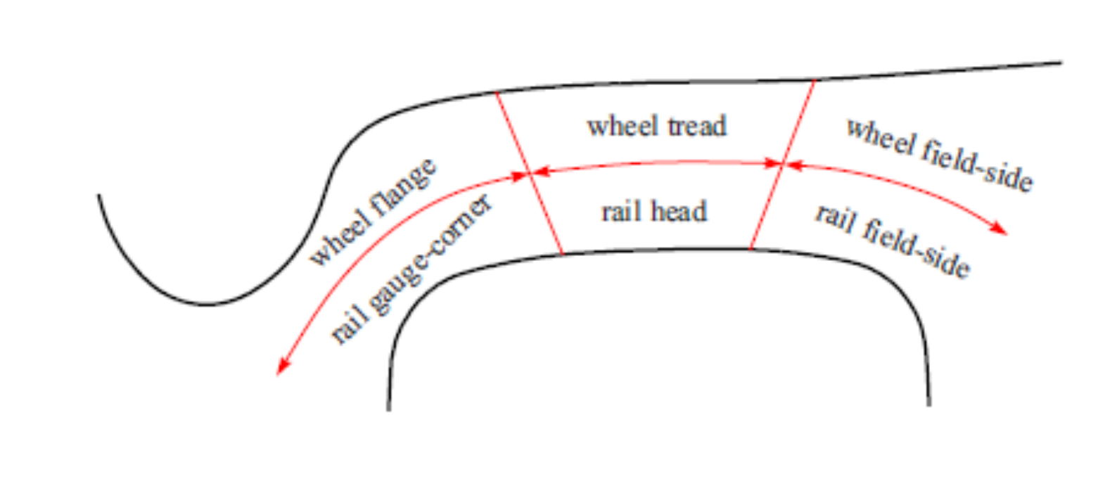 (a) Wheel tread, flange, gauge-corner, and field-side contact zones
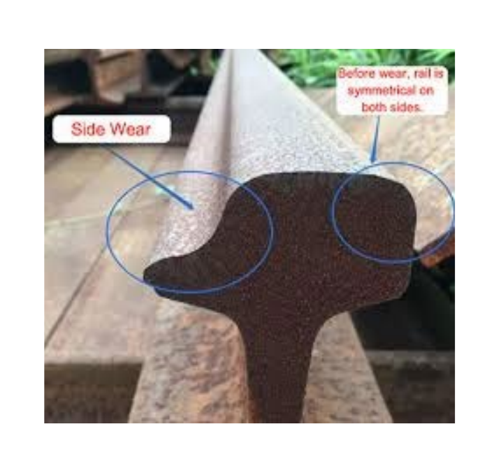 (b) Gauge-corner side wear on a worn rail profile
Vertical wear (crown wear; høydeslitasje) occurs on the rail crown and reduces the rail height, mainly in the tread–rail-head contact zone in Figure 15.5(a). Bane NOR evaluates rail wear using a combined total-wear measure that includes vertical wear and both sides of lateral wear; for 60E1 rail the allowable value depends on overbygning class and sleeper spacing rather than on crown loss alone [13]. Wear rates on curved track can exceed 0.3 mm per MGT under high contact forces [115].
Lateral wear (gauge-face wear; sideslitasje) occurs on the high rail gauge corner in curves, where the wheel flange contacts the rail with a large angle of attack and high contact force, as illustrated in Figure 15.5(b). Severe gauge-face wear widens the gauge and changes the rail head profile, altering the wheel–rail contact geometry and potentially creating unfavourable contact conditions.
Rail profile grinding can restore the gauge corner profile and redistribute the contact stress, significantly reducing lateral wear rates. Anti-wear rail grades (R320Cr, R350HT) provide a harder running surface and reduce wear rates by a factor of 2–3 compared with standard R260 grade.
15.2.3 Shelling
Shelling (avskalling) is the detachment of thin, flat pieces of material from the rail head surface. It arises when subsurface horizontal cracks, propagating at the boundary between the hardened near-surface layer and the underlying bulk material, reach the surface and cause delamination. Figure 15.6 shows the crack plane and the resulting local material loss at the gauge corner. Shelling is common where the head-hardened zone is thin and the traffic is heavy. It is detected visually and by ultrasonic testing.
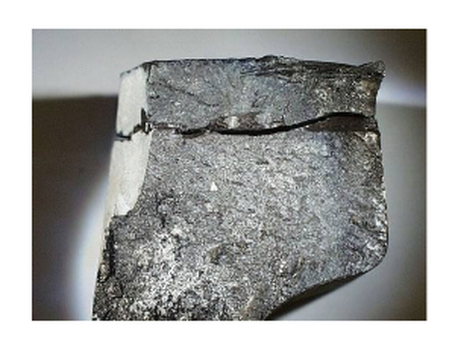
(a) Horizontal crack plane in the rail head
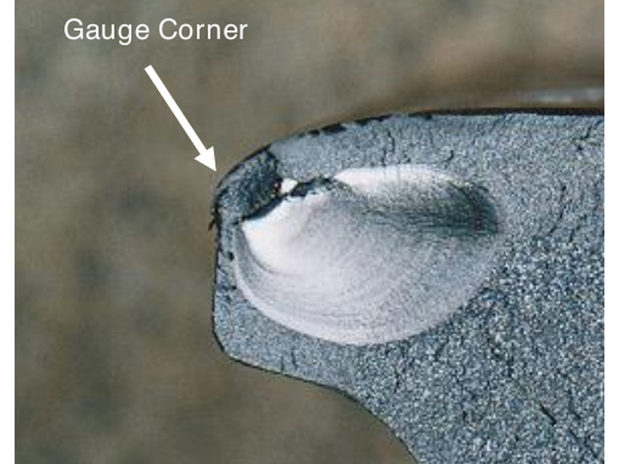
(b) Local shelling/spalling at the gauge corner
15.3 Rail Internal Defects
Internal rail defects are cracks or flaws that develop within the body of the rail, below the surface. They are more dangerous than surface defects because they are not visible to visual inspection, and they can propagate suddenly to cause rail fracture under traffic loading.
15.3.1 Transverse Defects
Transverse defects (tverrsprekker) are cracks oriented approximately perpendicular to the rail axis. They can originate from:
-
Propagation of head checks or squats that turn downward ("dive" cracks).
-
Hydrogen-induced cracking at inclusions in the rail steel (hydrogen embrittlement, most common in older rail manufactured with inadequate degassing).
-
Fatigue cracks at weld defects or rail foot contact points.
-
Shatter cracks (internal hydrogen flakes) in older rail.
Transverse defects are the most critical rail failure mode because they can cause rail fracture (skinnebrudd), a complete transverse break of the rail [65, 115]. Rail fracture is a primary derailment risk and is treated as an emergency requiring immediate track closure and rail replacement.
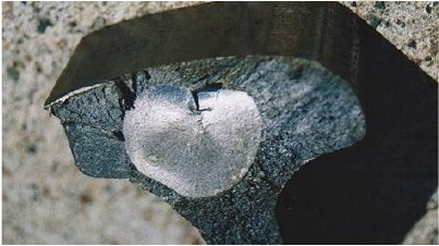
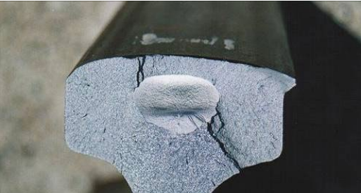
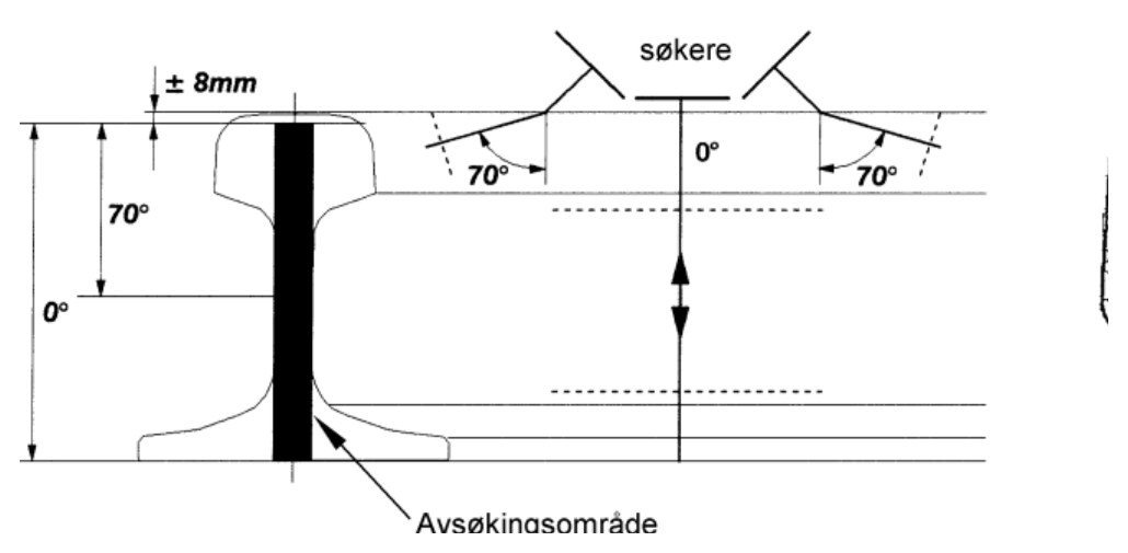
Transverse defects are detected by ultrasonic rail testing. Rail-testing systems use several probe angles; angled probes, often including \(70^\circ\) beams in rail-head inspection, are used so the ultrasonic beam intersects cracks that are roughly transverse to the rail axis. Automatic registrations must be followed up by qualified manual ultrasonic and visual control according to Bane NOR's rail-maintenance rules [13]. Figure 15.7 shows two examples where internal transverse cracking grew unseen inside the rail head until the section fractured.
 (a) Transverse fatigue defect in the rail head
 (b) Rail-head fracture from an internal defect
15.3.2 Weld Defects
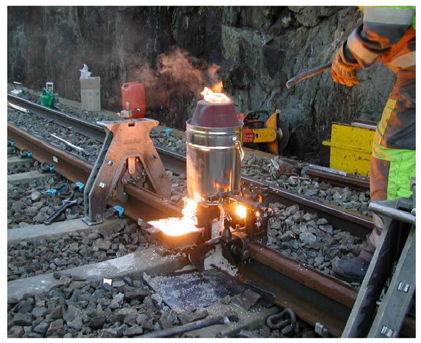
Weld defects occur at thermite (aluminothermic) or flash-butt welds. Common weld defects include:
-
Lack of fusion (bindefeil): incomplete bonding between the weld metal and the rail steel.
-
Porosity: gas pockets in the weld metal that reduce cross-sectional area.
-
Hot cracking: solidification cracks in the weld during cooling.
-
Poor profile: a weld "hump" or "dip" that creates a local impact load.
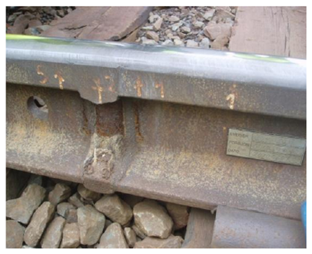
The visible weld zone in Figure 15.8 is the location where inspectors look for poor profile, cracks, lack of fusion, and other weld irregularities after installation and during service.
(a) Thermite weld being made in track
(b) Finished weld zone in the web and head
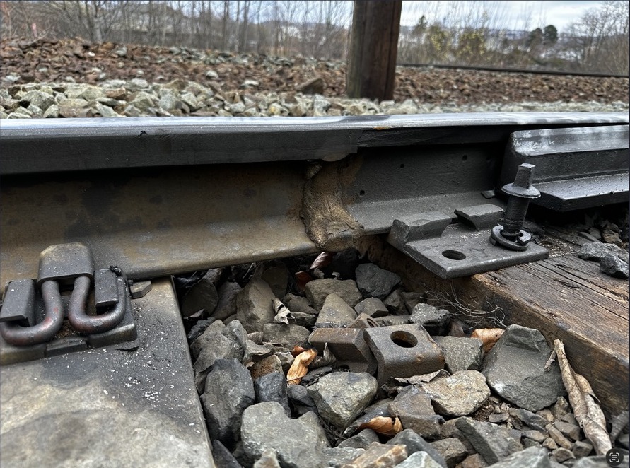
(c) Rail-web and fastening field context
All welds are inspected by ultrasonic testing after installation and at regular intervals during service. Profile measurement ensures that weld humps and dips are within tolerance.
15.4 Sleeper Defects
Sleeper defects are important because they affect both rail support and gauge restraint. The failure mode depends strongly on sleeper material, fastening type, drainage, and traffic loading.
15.4.1 Concrete Sleeper Defects
Prestressed concrete sleepers are durable, but subject to the following failure modes and material degradation patterns:
Cracking at the rail seat: The alternating tensile and compressive stresses under the rail seat can initiate fatigue cracks in the concrete at the rail seat centre. In severe cases, the sleeper fractures transversely beneath the rail. Defective rail seat pads that concentrate stress rather than distributing it accelerate this failure mode.
Longitudinal cracking: Longitudinal cracks along the sleeper soffit may result from inadequate concrete cover, chloride-induced corrosion of the prestressing wires, or freeze-thaw cycling of water in the concrete pores. Corroded prestressing wires cause the concrete to spall.
End splitting: Transverse cracks at the sleeper ends may form due to inadequate concrete mix design or manufacturing defects. End splits reduce the effective bearing area and can propagate to structural failure.
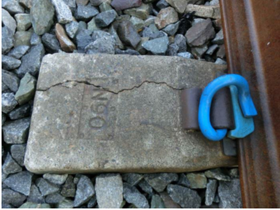
Alkali–silica reaction (ASR): Alkalis from the cement react with reactive silica in the aggregate to form a gel that expands when it absorbs water, cracking the concrete from within. ASR is recognised by several visible signs:
Map cracking: Fine, intersecting cracks form a polygonal pattern on the concrete surface as the expanding ASR gel strains the cover concrete. Figure 15.9 shows this early warning sign.
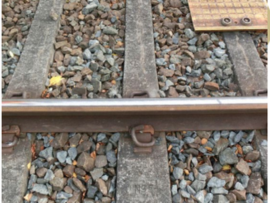
Affected sleepers in track: ASR may affect several sleepers from the same production batch or in the same wet environment. Figure 15.10 shows how the defect is assessed in its track context, not only on a single sleeper.
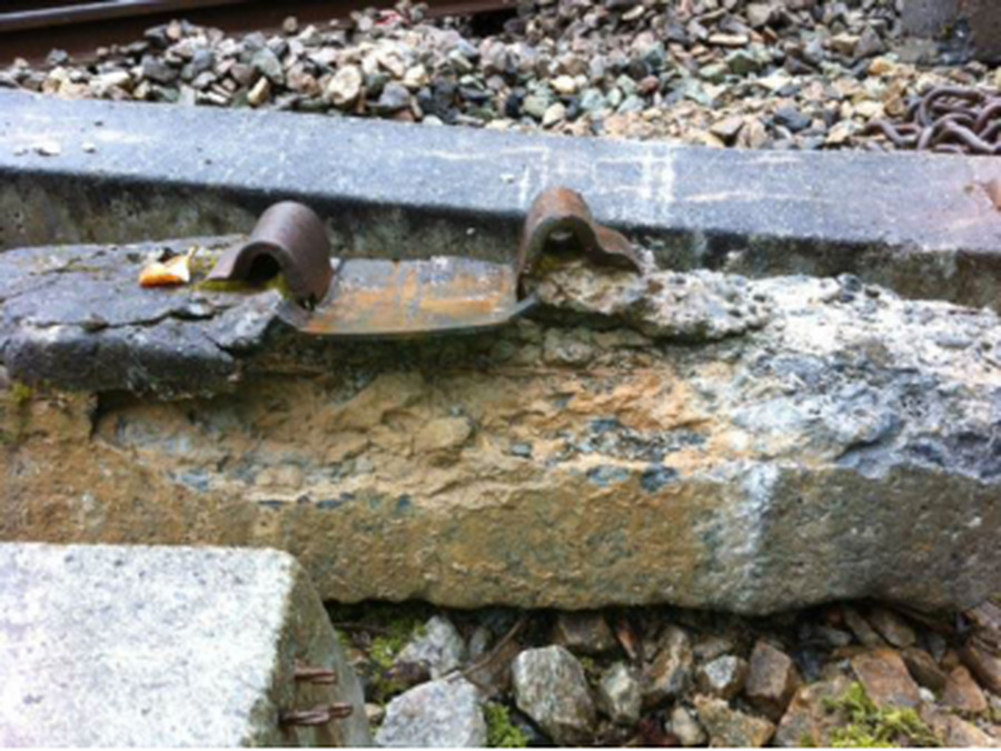
Surface scaling and spalling: As cracking opens the cover concrete, thin surface layers can detach and leave rough, scaled patches. Figure 15.11 shows the local surface loss associated with this damage.
Repeated damage pattern: If the underlying material problem or water exposure is common to a group of sleepers, similar damage can repeat along the track. Figure 15.12 shows this repeated pattern.
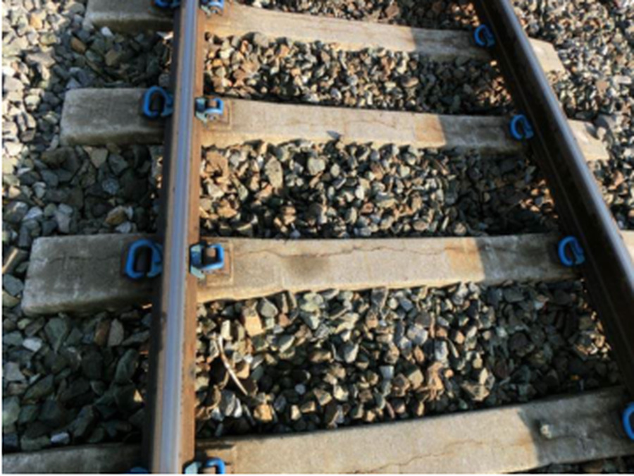
Concrete sleepers are inspected during walking inspections. Cracked or fractured sleepers are replaced individually when found; if multiple adjacent sleepers are defective, a section replacement is programmed.
15.4.2 Timber Sleeper Defects
Timber (wood) sleepers, found on secondary lines and sidings in Norway, fail through several visible mechanisms.
Rot (råte) is biological decomposition of the wood by fungi. It reduces the sleeper's strength and its ability to hold spikes and screws. Figure 15.13 shows the dark, weakened timber condition inspectors look for.
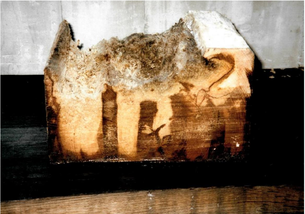
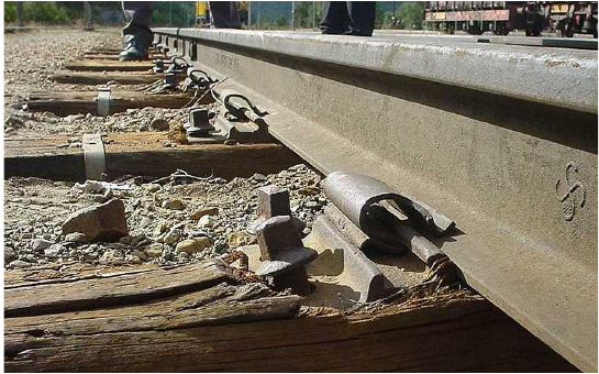
Spike killing is repeated spike or screw loading that widens the hole until the fastener no longer provides adequate resistance. The fastener must be moved to a new position or the sleeper replaced. Figure 15.14 shows a related rail-seat condition where the plate has cut into the timber and reduced the support around the fastening.
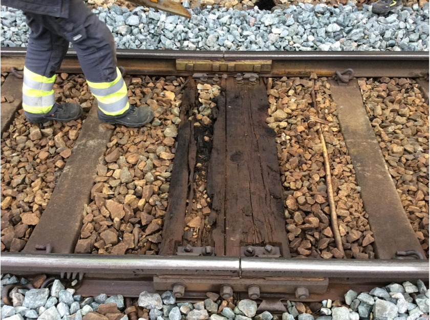
Splitting and cracking can result from tamping damage, local overload, frost action or long-term deterioration of the timber. Figure 15.15 shows a split sleeper where the timber no longer provides reliable support and fastener holding capacity.
The service life of timber sleepers on Norwegian lines is typically 15–25 years, depending on wood species (hardwood lasts longer than softwood), impregnation treatment, and traffic intensity.
15.5 Fastening Defects
Elastic rail fastenings (e.g. Pandrol e-clip, Vossloh W14) fail through:
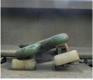
Fatigue of the clip: The elastic clip is subjected to millions of load cycles as trains pass. Fatigue cracks initiate at stress concentration points (bends in the clip). A fractured or ineffective clip provides no clamping force and must be replaced; Figure 15.16 shows the type of failed clip or anchorage condition that inspectors look for.
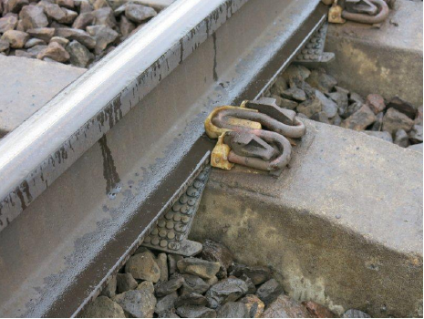
Deterioration of the rail seat pad: The elastomeric rail seat pad softens, wears, or is displaced under traffic loading, reducing its vibration isolation and load distribution properties. Figure 15.17 shows a displaced pad condition; pad replacement is routine.
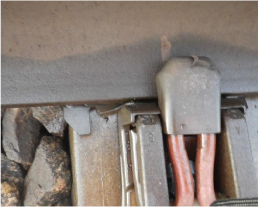
Loss of insulators: Electrical insulators that prevent current leakage between rail and sleeper can wear, crack, or fall out. Figure 15.18 shows a damaged insulator; missing insulators can cause short circuits in the track circuit signalling system.
Fastening defects are detected during walking inspections. A practised track inspector can identify missing, fractured, displaced, or worn fastening components visually; automated systems using machine vision are being introduced on high-traffic lines to target the same visible conditions.
15.6 Ballast Defects
As described in Chapter 3, ballast deteriorates through three common field mechanisms:
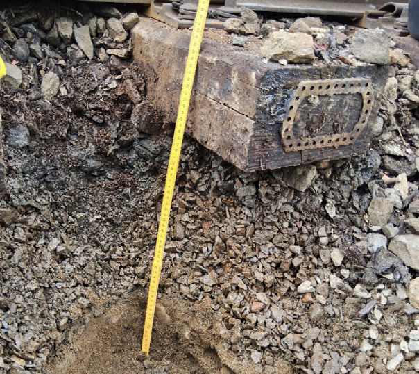
Fouling (ballastforurensning): Accumulation of fines from particle breakdown, sleeper wear, and subgrade contamination. Fouling impairs drainage and reduces the load-distribution and geometry-stabilising functions of the ballast. Figure 15.19 shows open ballast voids filled by fine material reaching the sleeper soffit. Fouling is assessed by the Fouling Index (FI) from sieve analysis [144].
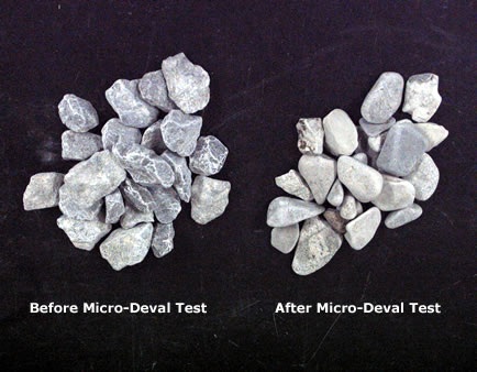
Particle breakdown: Repeated load cycling and tamping progressively crush and abrade ballast particles, reducing their size and angularity. Figure 15.20 shows the visual effect of mechanical abrasion: sharp angular particles become smaller and more rounded. Rounded, finely crushed particles do not interlock well and provide less lateral resistance.
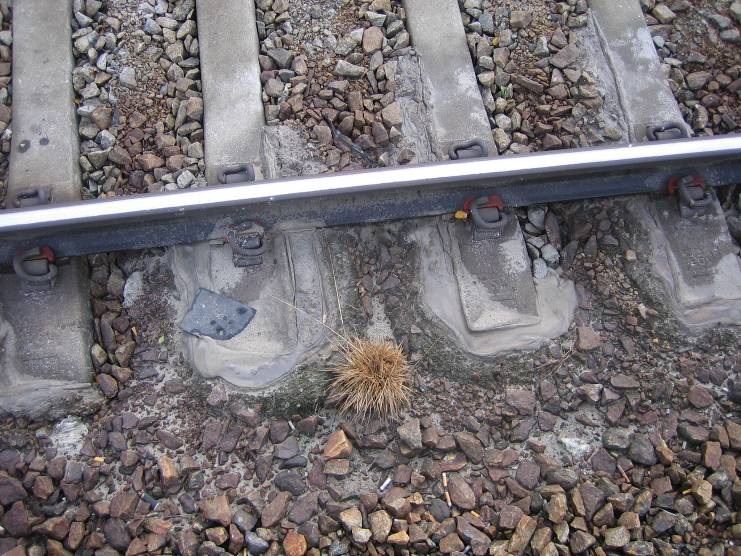
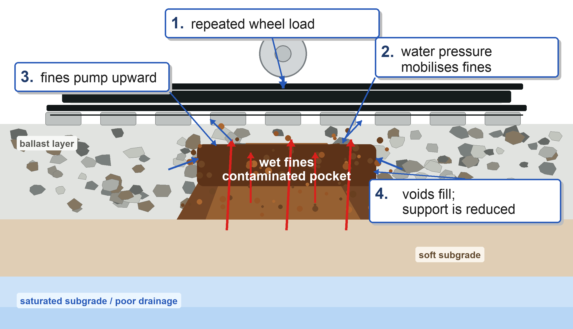
Mud pumping: On lines with poor subgrade drainage, water and fine subgrade material collect at the ballast–subgrade interface. Under repeated wheel loads, the local water pressure rises and mobilises the saturated fines; these fines are then squeezed upward through the ballast voids. The field sign is wet, pale or dark contaminated material at sleeper and rail-seat level, as shown in Figure 15.21. Once the voids are filled with fines, drainage and load distribution deteriorate, the sleeper loses support and moves more under traffic, and the pumping process accelerates. These spots require prompt intervention, normally combining subgrade stabilisation or drainage improvement with ballast renewal. The pumping mechanism is shown schematically in Figure 15.22.
15.7 Subgrade and Embankment Defects
Subgrade defects cause long-wavelength geometry irregularities that cannot be corrected by tamping alone:
Differential settlement: Non-uniform compressibility of the subgrade (at transitions from embankment to bridge or tunnel, at changes in soil type) creates differential settlements that manifest as geometry dips at the transition. Figure 15.23 shows the kind of severe longitudinal level distortion that develops when support is lost locally. These "transition zones" require intensive maintenance and are a primary cause of geometry deterioration on older Norwegian lines.
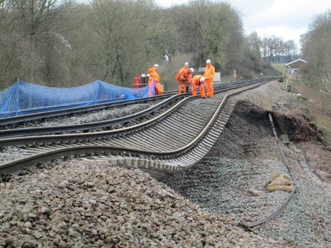
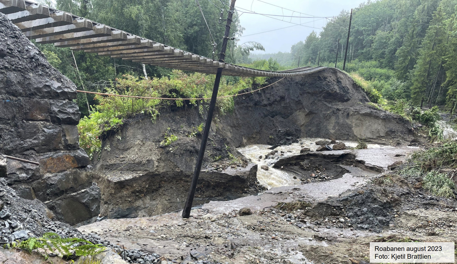
Erosion and scouring: Water flowing beneath or through the subgrade can erode fine particles, creating voids that cause sudden settlement. Inadequate drainage, broken culverts, and erosion at embankment toes are common causes. Figure 15.24 shows a severe washout where flowing water has removed the support below the track.
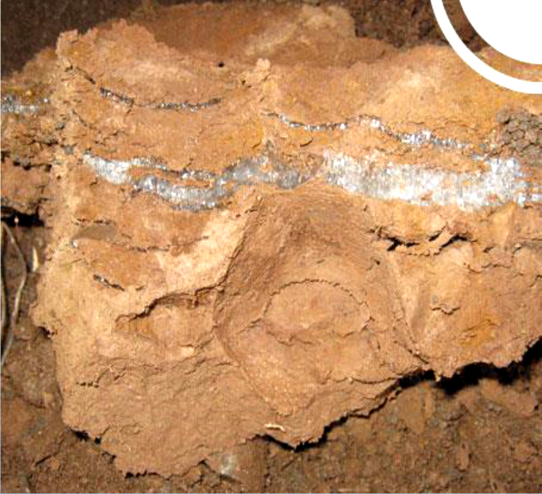
Frost heave: Seasonal frost penetration into frost-susceptible (silty) subgrade soils causes frost heave, which uplifts the track in winter and is followed by settlement in spring. The mechanism is the growth of ice lenses in the soil, illustrated in Figure 15.25. Frost protection layers (non-frost-susceptible fill, extruded polystyrene foam insulation) mitigate this.
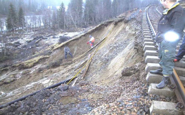
Slope failure: Embankment slopes and rock cuttings may fail under saturated conditions (heavy rainfall) or under earthquake loading. Figure 15.26 shows a trackside slope failure where the ground supporting the formation has moved. Slope failures are the most geographically variable subgrade failure mode on the Norwegian network, which traverses challenging terrain.
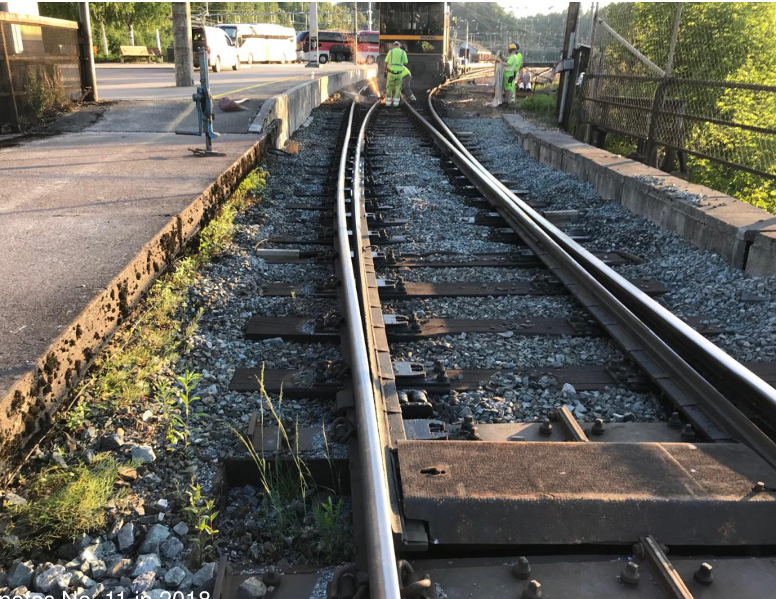
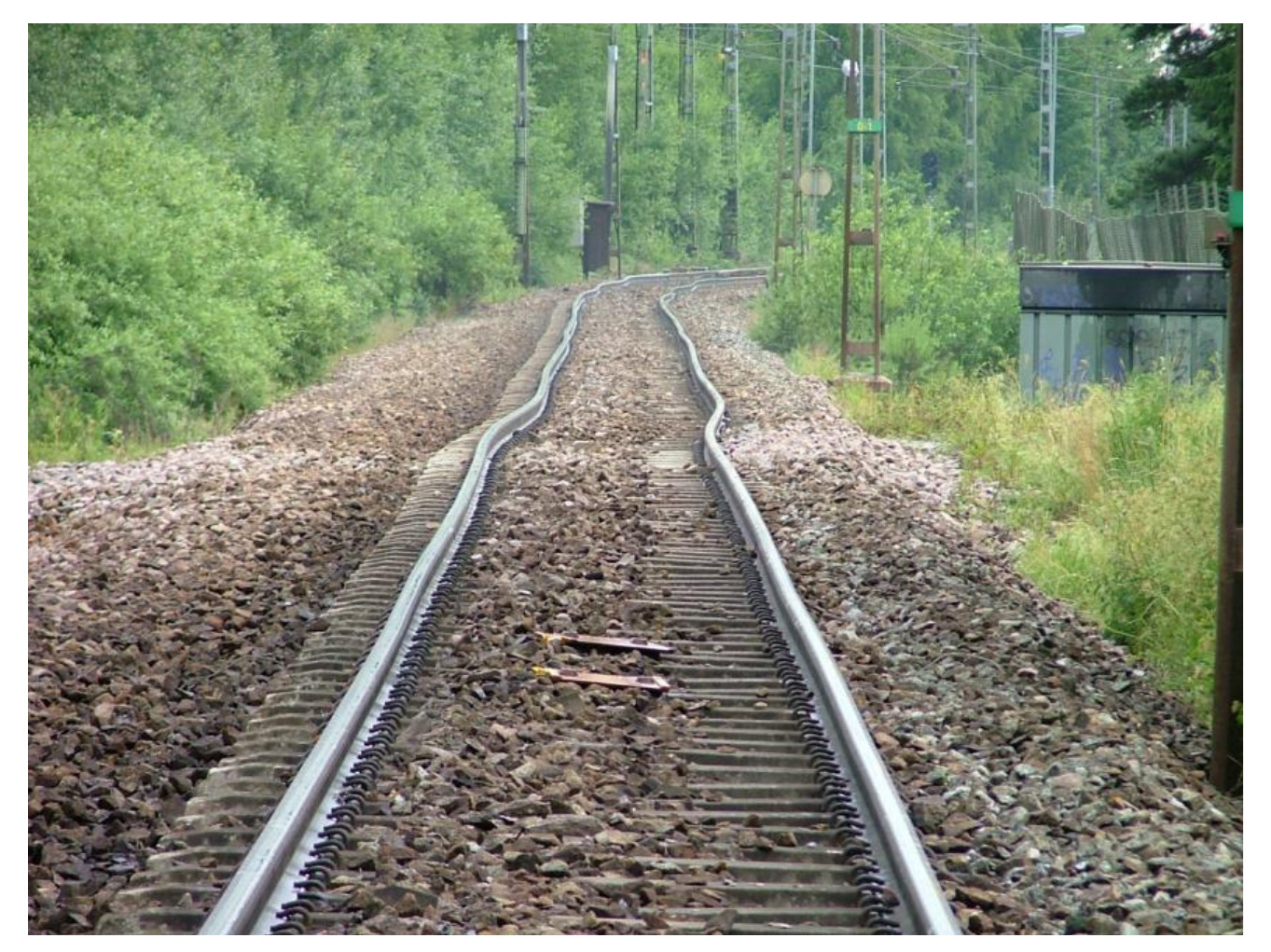
Track buckling (solslyng): On CWR lines, insufficient lateral ballast resistance combined with high rail temperature can cause the track to buckle laterally out of alignment. As described in Chapter 9, the thermal compressive force in the rail must be resisted by the ballast–sleeper lateral resistance. The critical temperature rise is not a fixed universal number; it depends on neutral temperature, curve radius, lateral resistance, alignment defects, recent tamping, ballast shoulder condition, and the restraint from fastenings and sleepers. A section with fouled ballast, fresh tamping, inadequate shoulder width, or a shifted neutral temperature therefore needs special attention during warm weather. Buckling is a high-severity incident that requires immediate track closure [6, 157, 65].
The buckles in Figure 15.27 show the typical sharp lateral misalignment that develops within seconds once the compressive rail force exceeds the local lateral resistance.
15.8 Geometry Defects
Track geometry defects are deviations of the track alignment and cross-section from the design values. They are the integrated result of all the component defects described above, plus the elastic and plastic deformation of the track under repeated loading. The five geometry parameters and their tolerance limits are described in Chapter 16 Section 16.3. Figure 15.28 shows the EN 13848-1 measurement sketches used to define these parameters.
![Track-geometry parameters and measurement signatures: gauge, longitudinal level, horizontal alignment, cross-level, and twist, adapted from EN 13848-1 [89].](../../assets/chapters/ch15/original/figures_lecture_crops/fig_geom_gauge_diagram_crop.png)
![Track-geometry parameters and measurement signatures: gauge, longitudinal level, horizontal alignment, cross-level, and twist, adapted from EN 13848-1 [89].](../../assets/chapters/ch15/original/figures_lecture_crops/fig_geom_longitudinal_level_diagram_crop.png)
![Track-geometry parameters and measurement signatures: gauge, longitudinal level, horizontal alignment, cross-level, and twist, adapted from EN 13848-1 [89].](../../assets/chapters/ch15/original/shared/ch16_rail_maintenance/figures_lecture_crops/fig_geom_horizontal_alignment_lecture.png)
![Track-geometry parameters and measurement signatures: gauge, longitudinal level, horizontal alignment, cross-level, and twist, adapted from EN 13848-1 [89].](../../assets/chapters/ch15/original/figures_lecture_crops/fig_geom_cross_level_diagram_crop.png)
![Track-geometry parameters and measurement signatures: gauge, longitudinal level, horizontal alignment, cross-level, and twist, adapted from EN 13848-1 [89].](../../assets/chapters/ch15/original/figures_lecture_crops/fig_geom_twist_diagram_crop.png)
The most safety-critical geometry defect is track twist, illustrated in Figure 15.28(e): a change of cross-level over a short distance. Twist reduces the vertical load on the diagonal wheel pair, and if severe, can lead to wheel lift and potential derailment. The applicable immediate limit depends on quality class, measuring base and local rule set; Chapter 16 gives the full Bane NOR geometry-limit tables, while line-specific thresholds must be stated explicitly for any calculation or decision [48].
Differential settlement at transition zones (overgangssoner) is the most common cause of repeat geometry complaints on the Norwegian network. Where a slab track section meets a ballasted section, or where a bridge abutment meets an embankment, the difference in track stiffness creates a longitudinal-level defect (Figure 15.28(b)) that rapidly re-develops after tamping. These zones require engineering interventions beyond tamping: grout injection, stiffening pads, or transition slabs.
15.9 Inspection Methods
Each inspection method answers a different question. Walking inspection shows visible defects, ultrasonic testing finds hidden rail and weld defects, eddy current testing measures shallow RCF cracks, track recording vehicles measure the track geometry, and GPR supports ballast and subgrade assessment. A reliable defect assessment normally combines several methods rather than relying on one observation.
15.9.1 Walking Inspection
Walking inspection (linjevisitasjon) remains the backbone of defect detection for defects that have progressed to surface visibility: fractured clips, broken sleepers, missing fastenings, obvious rail-head defects, mud pumping spots, and drainage problems. Trained track inspectors cover assigned sections at regular intervals and record the defect location, severity and corrective action. Walking inspection is therefore a condition check for visible components, not a substitute for ultrasonic rail testing or track geometry measurement.
15.9.2 Vehicle-Mounted Ultrasonic Testing
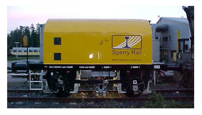
Vehicle-mounted ultrasonic testing (UT) is used for production testing of long rail sections and welds. The vehicle in Figure 15.29 carries several probes and records internal indications while moving along the line. This method is used because transverse cracks, weld flaws and split-head defects can be hidden inside the rail and cannot be found reliably by walking inspection.
15.9.3 Manual Ultrasonic Trolley Verification
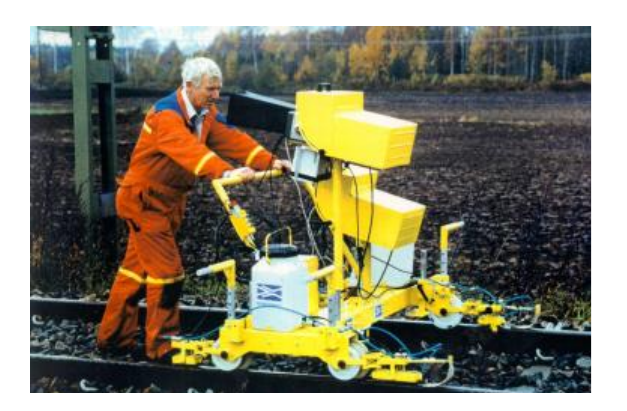
Manual ultrasonic trolleys are used for local verification after a vehicle-mounted system has reported an indication, and for slower detailed inspection at welds or short critical sections. Figure 15.30 shows the scale of this method: the inspector works directly at the track and can repeat the measurement over the suspected location.
15.9.4 Ultrasonic Probe Coverage and B-Scan Output
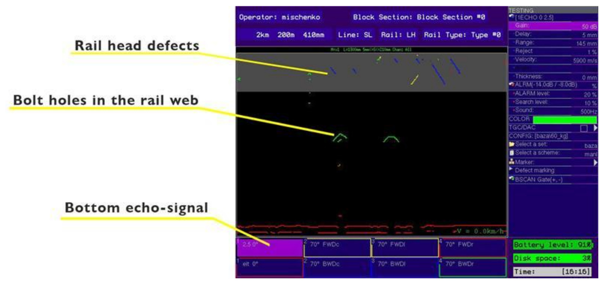
The ultrasonic probes must cover the parts of the rail where cracks are expected. Figure 15.31 shows why different beam angles are used: normal-beam probes detect horizontal laminations and shelling, angled probes detect transverse defects, and surface-wave probes help with near-surface head checks. The result is interpreted on the inspection display; in Figure 15.32, the B-scan shows where reflectors occur in the rail profile and whether they require verification or immediate response.
15.9.5 Eddy Current Testing
Eddy current (EC) testing is used for surface and near-surface RCF defects, especially head checks and shallow cracking in the running band. An electromagnetic coil induces eddy currents in the rail-head surface layer; surface cracks disturb the current field and are detected by a sensor. EC testing complements UT: it is sensitive to shallow surface cracking, but it cannot detect deep internal rail or weld defects.
15.9.6 Track Recording Vehicles and Geometry Measurement
Track recording vehicles (TRV), also called diagnostic or measurement vehicles, are the platform used to collect repeatable track-condition data at line speed (Figure 15.33). The vehicle shown here is the ROGER 1000, a 24 m, 62 t measurement train built by Mermec and used in Norway for traffic-speed inspection of rails and overhead lines [164]. For geometry inspection, track recording vehicles carry inertial measurement units, laser profilometers and optical alignment systems that measure gauge, longitudinal level, alignment, cross-level and twist (see Chapter 16). Repeated runs make it possible to find trends, not only single defects: transition-zone dips, track twist and settlement can be identified from how the measured geometry changes over distance and over time.
![ROGER 1000 track recording vehicle used for repeatable geometry and track-condition measurements [164].](../../assets/chapters/ch15/original/figures_lecture_crops/fig_track_recording_vehicle_roger1000.jpg)
15.9.7 Ground-Penetrating Radar
Ground-penetrating radar (GPR) is used to assess ballast and subgrade condition from the surface. GPR can identify ballast fouling zones, mud pumping spots and void formation beneath sleepers without excavation [144, 124, 165, 107]. Figure 15.34 shows a practical railborne arrangement: antenna units are mounted below the vehicle frame, while the data logger and processing software convert reflected radar signals into layer boundaries, moisture and fouling information. It is often mounted on the same multi-function recording vehicle as the geometry equipment, but it is a different sensor system: GPR explains support and drainage condition below the sleepers, while geometry measurement shows the track response at rail level.
![IDS GeoRadar SRS SafeRailSystem for railway ballast inspection: vehicle-mounted antenna equipment and interpretation output [107].](../../assets/chapters/ch15/original/figures_repaired/fig_gpr_srs_equipment_ids.png)
![IDS GeoRadar SRS SafeRailSystem for railway ballast inspection: vehicle-mounted antenna equipment and interpretation output [107].](../../assets/chapters/ch15/original/figures_repaired/fig_gpr_srs_data_view_ids.jpg)
Table 15.4 summarises the normal pairing between defect family, field symptom, inspection method and maintenance response.
| Defect family | Typical field symptom | Primary inspection method | Typical response |
|---|---|---|---|
| Rail surface | Head checks, squats, corrugation, wear bands | Walking inspection, eddy current, profile or roughness measurement | Grinding, local repair, or rail replacement if cracks are deep |
| Rail internal and welds | Transverse cracks, weld flaws, split head defects | Vehicle-mounted UT, manual trolley verification, normal and angled probes | Speed restriction, urgent verification, or rail replacement |
| Sleepers and fastenings | Cracked sleepers, missing clips, pad or insulator damage | Walking inspection and image-based inspection | Component replacement and gauge-restraint check |
| Ballast and subgrade | Fouling, mud spots, settlement, drainage failure | Walking inspection, track recording vehicle trends, GPR or excavation | Drainage repair, ballast cleaning, subgrade treatment, or renewal |
15.10 Defect Classification and Severity Limits
Systematic defect classification is essential for comparing condition data between lines, tracking trends over time, and triggering the correct maintenance response. Different defect families are not classified in exactly the same way: Bane NOR rail defects are assigned to defect groups with follow-up rules, while geometry defects use maintenance, action and immediate limits. For preliminary assessment, the common decision logic can be represented by the three response bands below [13, 48, 65].
15.10.1 Defect Severity Levels
For geometry defects, the response logic can be explained using three escalating limit levels. Bane NOR's geometry tables use the terms vedlikeholdsgrense, tiltaksgrense and umiddelbar grense. The related maintenance-workflow abbreviations are [31]:
-
Preventive maintenance inspections (FVK; forebyggende vedlikeholdskontroller).
-
Deferred corrective maintenance (utsatt korrektivt vedlikehold, UKV).
-
Urgent corrective maintenance (akutt korrektivt vedlikehold, AKV).
| Limit level | Description | Maintenance response |
|---|---|---|
| Maintenance limit | ||
| (vedlikeholdsgrense) | Defect has exceeded the planned-maintenance limit but has not yet reached the action limit. | Plan and follow up so the defect is corrected before the action limit is expected to be exceeded; if a corrective work order is raised, it is normally handled as UKV. |
| Action limit | ||
| (tiltaksgrense) | Defect has reached the level where corrective action is required. | Correct the defect and follow it up so the immediate limit is not exceeded before the next measurement; this is normally planned corrective follow-up rather than AKV. |
| Immediate limit | ||
| (umiddelbar grense) | Defect has exceeded the immediate limit or has an uncertain safety margin. | Start AKV: repair immediately and reduce speed or close the track as required by the defect rule. |
This three-band structure maps directly to the geometry tolerance logic in Chapter 16, Section 16.3. For rail defects, the official Bane NOR rail-defect catalogue gives the controlling defect group and deadline; the head-check depth bands below are therefore used as screening bands for preliminary analysis, not as a complete replacement for the catalogue.
| Severity | Crack depth [mm] | Action |
|---|---|---|
| Alert | \(< 1\) | Record; monitor; include in next preventive grinding cycle. |
| Intervention | 1–3 | Corrective grinding (remove to below crack tip depth). |
| Priority intervention | 3–5 | Urgent corrective grinding or local rail replacement planning; consider temporary monitoring or restrictions depending on line speed and crack angle. |
| Immediate action | \(> 5\) | Immediate verification, corrective grinding or rail replacement; consider speed restriction. |
15.11 Defect Recording and Reporting
Defect recording converts field observations into maintenance decisions. The value of the inspection depends on consistent coding, severity classification, and traceable follow-up.
15.11.1 Defect Coding
Bane NOR records detected defects in maintenance and infrastructure-data systems using standardised defect coding and follow-up workflows. For rail defects, automatic ultrasonic registrations are followed up by manual ultrasonic and visual control, and rail defects are reported through Bane NOR's rail-defect follow-up tool (UL-kontroll) before the data is transferred to infrastructure records (Banedata) [13]. The rail defect catalogue (Katalog over feil og brudd i skinner) uses the UIC-based 3- or 4-digit defect code (feilkode/UIC-kode) and assigns a defect group (feilgruppe) that controls the response: group 2b (hold skinnen under observasjon), group 2a (ta ut feilen), group 1 (ta ut feilen snarest) or group 0 (ta ut feilen umiddelbart og innfør trafikkrestriksjoner) [36].
| Coding field | Norwegian term | Use in the defect record |
|---|---|---|
| Location | stedfesting: bane/strekning, spor, km, skinnestreng | Find the same defect again and compare it with traffic, geometry and maintenance history. |
| Component or object | objekt, komponent | Rail, weld, sleeper, fastening, ballast, drainage, subgrade or other asset. |
| Defect code | feilkode, UIC-kode | Official rail-defect code; identifies location in the rail, profile position and damage or crack type. |
| Defect type | feiltype, skadetype | Readable name, e.g. head checking (kjørekantsprekker), squat (sprekker og lokale nedsenkninger) or rail break (skinnebrudd). |
| Severity or defect group | alvorlighetsgrad, feilgruppe | Response category. Rail defects use groups 0, 1, 2a and 2b in the catalogue. |
| Dimension or extent | feilstørrelse, utbredelse | Measured depth, length, area, width, missing material or other classification dimension. |
| Detection method | kontrollmetode, funnmetode | Visual inspection (visuell kontroll), UT (ultralydkontroll), EC (virvelstrømkontroll), measurement vehicle (målevogn), GPR (georadar) or excavation. |
| Action and deadline | tiltak, utbedringsfrist | Monitoring, planned maintenance, urgent repair, immediate repair, speed restriction or track closure. |
15.11.2 Defect Trend Analysis
Accumulated defect records form the basis for trend analysis: the important question is not only whether a single defect exceeds a limit, but whether the same type of defect is appearing more often, growing faster, or returning after maintenance. Bane NOR's technical regulations give several examples where trend information changes the maintenance decision. For rail defects, general rail fatigue is indicated by a marked increase in rail breaks or serious ultrasonic indications over a short section. If the number of rail breaks increases by 30% over a five-year period, starting from a break frequency of at least 6 per 10 km per year, rail replacement should be planned; the track is assessed in 10 km sections. The same rule treats the trend variable as either observed rail breaks or class 1 ultrasonic indications, while weld breaks are excluded and changes in inspection method must be considered when comparing years [13].
For geometry, trend analysis uses measurement-vehicle data. The Norwegian term is målevognsdata. Bane NOR defines the quality number, K-tallet, as the share of a section where all relevant standard-deviation values, \(\sigma\)-values, are within the quality limits. The K-number should be as high as possible; low values accelerate track degradation. If the K-number falls below the action limit, the cause of the poor quality must be assessed promptly, and possible compensating actions include speed reduction, track adjustment, component replacement or more frequent inspections until the defect is removed (see Section 16.3 for the calculation) [48].
| Trend indicator | Norwegian term / rule signal | Maintenance interpretation |
|---|---|---|
| Rail breaks and serious UT indications | skinnebrudd; class 1 indications from ultralydkontroll | A 30% increase over five years, with at least 6 breaks per 10 km per year as basis, triggers rail-replacement planning in 10 km sections. |
| Visible contact-fatigue cracking | kontaktutmatting; head checks and squats | Increasing RCF means the grinding interval, lubrication, rail grade and curve contact conditions should be reviewed. |
| Gauge change over time | sporviddeendring over tid | A change of 6 mm or more in one year requires investigation; rapid change indicates sleeper or fastening deterioration. |
| Geometry quality number | K-tallet; section-based \(\sigma\)-value check | Low K-values trigger cause analysis and possible adjustment, component replacement, speed reduction or increased inspection frequency. |
| Repeated geometry exceedances | oppfølging av sporgeometriske feil | Plan maintenance-limit exceedances before the action limit is expected to be reached; repeats suggest support or drainage causes. |
15.11.3 Worked Example: Rail-Break Trend Decision
Question. A 10 km section recorded an average of 6.0 qualifying rail breaks per year five years ago. The current annual value is 8.0. The inspection method and reporting coverage have remained unchanged, and weld breaks have been excluded. Does the trend meet the rail-replacement planning criterion described above, and what should the engineer do next?
Step 1: check the starting frequency. The rule is applied only when the starting frequency is at least 6 breaks per 10 km per year. Here,
so the starting-frequency condition is satisfied.
Step 2: calculate the five-year increase.
Step 3: compare with the trend criterion. Because \(33.3\,\%>30\,\%\), both parts of the planning criterion are met: the baseline is at least 6 and the increase exceeds 30 %. Rail replacement should therefore enter the renewal plan for the assessed 10 km section.
Engineering interpretation. The trend rule is a planning trigger, not an automatic statement that the whole section must be closed immediately. The engineer must still localise the breaks and class 1 ultrasonic indications, confirm that the data series is comparable, investigate traffic and rail-grade history, and apply the required immediate response to any individual safety-critical defect. A complete maintenance plan must extend this single-trend decision to RCF, ultrasonic indications, geometry, ballast, drainage, and bridge-transition behaviour.
15.12 Chapter Summary
Central idea. Track defects should be read as symptoms of a mechanism in the whole track system. Location, growth and consequence matter as much as the defect name: a surface crack, worn profile or geometry dip has different meaning depending on whether it is in the rail head, a weld, the rail seat, the ballast layer or a transition zone. The purpose of inspection is therefore to connect what is seen in the field with the cause, the severity and the required maintenance response.
Rail-head defects. The rail-surface part of the chapter separates crack defects from wear and roughness defects. Head checks and squats are rolling contact fatigue (RCF) cracks: head checks form on the gauge corner, often in curves, and may turn downward into transverse cracks; squats form dark depressed patches in the running band and can develop branching cracks. Corrugation is different: it is a periodic roughness and wear pattern rather than an RCF crack. Vertical and lateral wear remove material and change the wheel–rail contact geometry, while shelling is local delamination caused by horizontal or near-surface cracking.
Internal rail and weld defects. Internal rail defects are more safety-critical than ordinary surface damage because they may remain invisible until rail fracture. Transverse defects can grow from RCF cracks, hydrogen-related flaws, rail-foot fatigue or weld defects, and they require ultrasonic testing with suitable beam angles followed by manual verification when needed. Weld defects include lack of fusion, porosity, hot cracking and poor weld profile; the poor profile itself is important because it creates impact loading and can accelerate fatigue around the weld.
Support and restraint defects. Sleepers, fastenings, ballast and subgrade determine rail support and gauge restraint. Concrete sleepers may suffer rail-seat cracking, longitudinal cracking, end splitting and alkali–silica reaction; timber sleepers may suffer rot, plate cutting, spike-hole enlargement and splitting. Fastening defects such as broken clips, worn or displaced rail pads and damaged insulators reduce clamping force, load distribution or electrical insulation. These component defects often become track-system problems because poor support increases dynamic loading and can make rail defects and geometry deterioration return after local repair.
Ballast, drainage and formation defects. Ballast deterioration is mainly a loss of drainage and interlock. Fouling fills the voids with fine material, particle breakdown rounds and weakens the ballast stones, and mud pumping combines poor drainage, repeated wheel loading and saturated fines into a self-accelerating loss of support. Below the ballast, differential settlement, erosion and scouring, frost heave and slope failure produce long-wavelength geometry defects that tamping alone cannot remove. On CWR track, loss of lateral resistance or shifted neutral temperature can also lead to track buckling, which is an immediate safety-critical condition.
Geometry as the track response. Track geometry defects are the measured expression of deterioration in the track structure. Gauge, longitudinal level, horizontal alignment, cross-level and twist describe how the rail position has changed after the combined effects of rail damage, sleeper condition, fastening restraint, ballast support and subgrade movement. Twist is especially important because it can unload one wheel and increase derailment risk. Transition-zone dips are a good example of why mechanism matters: the defect may disappear after tamping but return quickly if the stiffness or support change at the transition is not corrected.
Inspection methods. The inspection part of the chapter shows that each method answers a different question. Walking inspection finds visible component damage and drainage or support warning signs. Vehicle-mounted ultrasonic testing screens long rail sections and welds for hidden defects, while manual ultrasonic trolleys verify local indications. Probe coverage and B-scan interpretation explain where the defect lies in the rail. Eddy current testing is suited to shallow surface RCF, track recording vehicles provide repeatable geometry and trend data, and GPR helps explain ballast and subgrade condition. No single inspection method is sufficient for all defect families.
From defect finding to maintenance decision. Defect classification and reporting turn field observations into decisions. Severity bands, rail-defect groups and geometry limits determine whether the response is monitoring, planned intervention, urgent repair, speed restriction or track closure. A useful record includes the location, component, defect code, defect type, severity, size, detection method, action and deadline. Trend analysis then checks whether the section is deteriorating over time: increasing rail breaks or class 1 ultrasonic indications, growing RCF, rapid gauge change, low K-tallet or repeated geometry exceedances all point to a maintenance need beyond the single visible defect. The engineering task is to remove or control the cause before the same damage pattern returns.
Assignments
Assignment 1: Identify rail-head surface defects
Use the four rail-head photographs below. For each panel, identify the defect, state the likely mechanism, and name the inspection or maintenance response that would normally follow. For panel (a), assume that the crack depth is about 3 mm and the crack spacing is about 3 mm. For panel (b), assume that ultrasonic follow-up finds no recordable transverse crack.
|
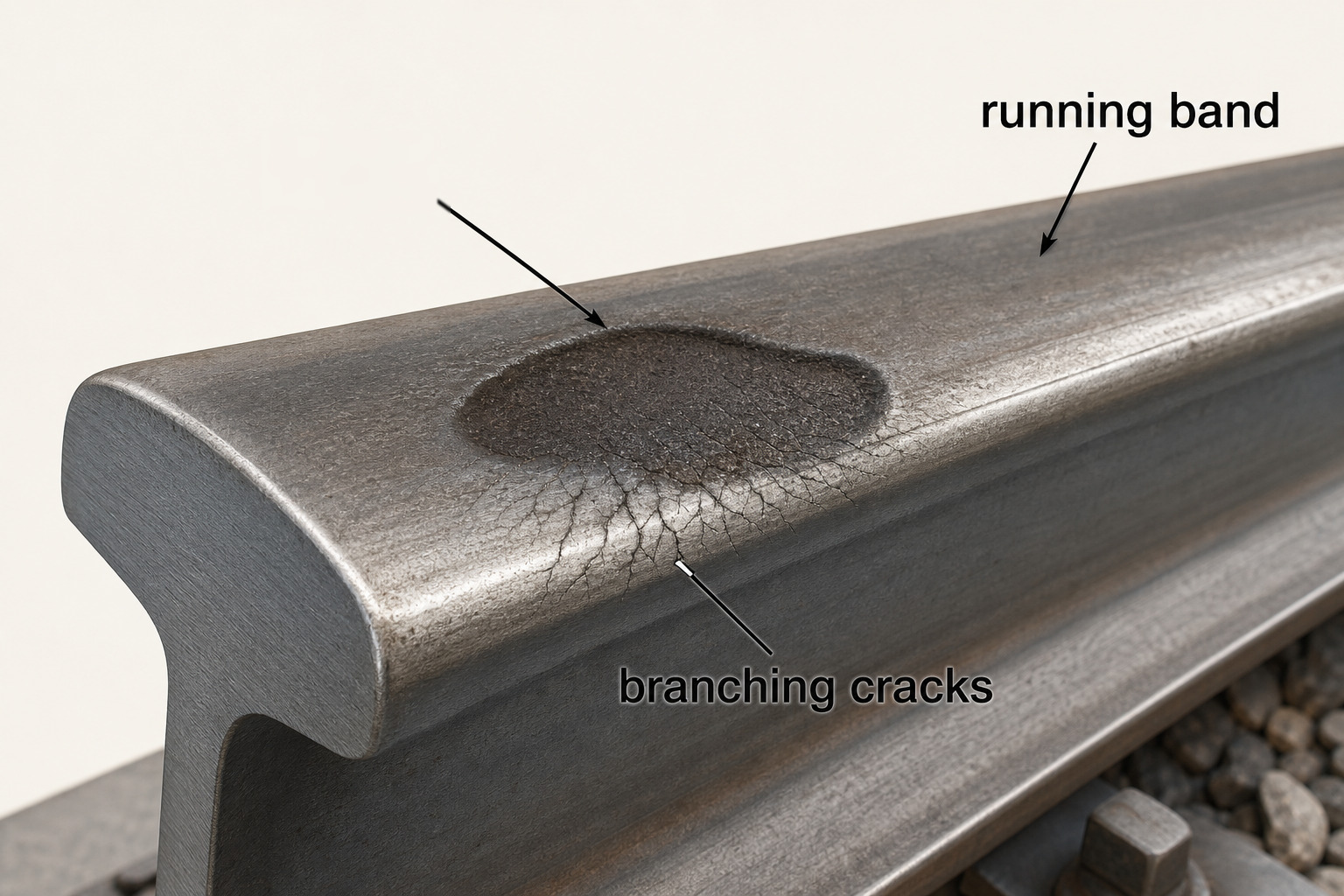 |
| \(a\) Gauge-corner cracking | \(b\) Dark depression on the running band |
|
 |
| \(c\) Periodic light–dark bands | \(d\) Local material loss at the rail head |
(a) For each panel (a)–(d), identify the type of rail-head damage shown.
(b) For each panel, classify the main process as RCF cracking, surface wear or roughness, delamination, or ordinary material loss.
(c) Use Tables 15.5 and 15.6 to classify panel (a), and use the Bane NOR group logic for panel (b).
(d) State which defects can develop into internal transverse rail defects if left untreated.
Assignment 2: Explain damage mechanisms
Answer the following without using photographs. The aim is to show that you can connect the visible defect, the physical mechanism and the maintenance logic.
(a) Explain the difference between rolling contact fatigue, ordinary rail wear, corrugation and shelling.
(b) Why can head checks and squats become more safety-critical if they turn downward into transverse cracks?
(c) Explain how corrugation is measured from the longitudinal running-surface profile. Include wavelength, RMS wave depth and peak-to-bottom wave depth in your answer.
(d) Why is rail grinding suitable for some rail-head defects but not sufficient when the crack or support problem has already progressed too far?
Assignment 3: Component defects and root causes
For each description below, identify the affected track component, the likely defect mechanism and one suitable maintenance response.
(a) A prestressed concrete sleeper has cracks around the rail seat after repeated traffic loading.
(b) A timber sleeper no longer holds the screw or spike tightly, and the hole has widened after repeated loading.
(c) Several elastic clips in a curve are fractured, and the remaining fastening system provides poor clamping force.
(d) Fine wet material appears repeatedly around sleepers after rain, and the same location loses level again soon after tamping.
(e) A bridge approach develops a recurring longitudinal-level dip even though it has been tamped several times.
Assignment 4: Select the inspection and reporting method
Choose a suitable inspection method for each situation and explain why that method is needed. Use the chapter terminology for walking inspection, ultrasonic testing, eddy current testing, track recording vehicles and ground-penetrating radar.
(a) A visible head-check area must be checked for shallow crack depth before deciding whether grinding is sufficient.
(b) A vehicle-mounted ultrasonic run reports a possible transverse defect close to a weld.
(c) A section has repeated longitudinal-level dips after tamping, but the visible rail and sleeper condition does not explain the problem.
(d) A maintenance engineer wants to compare the same defect over several inspections. Which fields should be recorded in the defect report?
(e) Explain the difference between a maintenance limit, an action limit and an immediate limit, including the Norwegian terms in parentheses.
Assignment 5: From trends to maintenance planning
A 10 km section has the following recurring condition records over three years: increasing head-check density in two curves, two class 1 ultrasonic rail indications, falling K-tallet, repeated mud pumping after wet periods, and a bridge-approach dip that returns within months after tamping.
(a) Identify the main defect families involved and explain which trends are safety critical.
(b) Decide which problems call for immediate corrective maintenance, which call for preventive maintenance, and which may indicate renewal or root-cause treatment.
(c) Explain why predetermined maintenance alone is not enough for this section.
(d) Propose a short maintenance plan that combines rail-defect follow-up, grinding or rail replacement, drainage/ballast work, geometry monitoring and reporting.