Structure Gauge
12.1 Introduction
The structure gauge defines the cross-sectional envelope that must remain clear of all fixed installations along the railway. It is one of the most fundamental interface requirements in railway engineering, governing everything from tunnel cross-sections and platform edge positions to catenary mast placement and signalling equipment. This chapter covers the definitions and Norwegian gauge profiles, curve overthrow calculations, the space required for moving vehicles, and the methods used to verify structure gauge compliance.
This introduction establishes the main gauging terms used throughout the chapter. The distinctions between vehicle profiles, dynamic reference profiles, and infrastructure clearances are important because later calculations assign responsibility to different parts of this hierarchy.
12.1.1 Structure Gauge
The basic structure-gauge envelope is the protected space around the track centre line and above top of rail. For new Norwegian lines, Bane NOR defines the dimensioned minimum cross-section shown in Figure 12.1; curve overthrow, cant effects and dynamic allowances are then added where required.
![Bane NOR minimum structure gauge for new lines [49].](../../assets/chapters/ch12/original/figures_lecture_crops/fig_banenor_new_line_structure_gauge.png)
The structure gauge (minste tverrsnitt) is the cross-section of the space on every side of and above the track that must be free of all obstacles. The civil engineer is responsible for ensuring that no structure or piece of equipment is placed inside this boundary. The hierarchy is easiest to read from the vehicle outward to the infrastructure clearance:
- A: Vehicle (construction) profile
-
The maximum static and dynamic envelope within which the vehicle and all its components must remain. Prescribed by the vehicle manufacturer and approved by the railway undertaking.
- B: Reference (dynamic) profile
-
The dividing boundary between vehicle and infrastructure responsibility, e.g. the Norwegian reference profile NO1. It encloses all dynamic movements of the rolling stock.
- C: Structure gauge
-
The minimum envelope the infrastructure must keep clear; determined by the reference profile plus infrastructure safety margins.
- D: Pantograph gauge (Cross-section E)
-
The special envelope for the overhead line system on electrified lines. It has no curve overthrow adjustment.
To separate infrastructure responsibility from rolling-stock responsibility, Figure 12.2 places these four envelopes in relation to one another, from the vehicle construction profile to the infrastructure clearance and pantograph gauge.
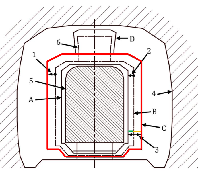
The numbered arrows in Figure 12.2 mark the smaller interfaces inside the same hierarchy. In Bane NOR terminology the minimum cross-section must remain free for train passage, is widened where curve and dynamic effects require it, and is supplemented on electrified lines by the free pantograph profile and Cross-section E [49, 39]. In the figure, the numbers denote: (1) vehicle-side allowance from the actual vehicle outline to the maximum vehicle profile and reference profile; (2) the infrastructure-side allowance from the reference profile to the structure gauge; (3) local lateral addenda such as curve overthrow, cant-related displacement and dynamic movement; (4) the fixed works or tunnel boundary; (5) the actual vehicle outline, including body and load; and (6) the pantograph/electrification envelope, checked separately by the free pantograph profile and Cross-section E.
The coordinate system for gauging is measured perpendicular to the track plan (the imaginary horizontal plane between the two rail heads), centred on the track centre line. Heights are measured above the top of rail (TOR).
12.1.2 Static and Dynamic Profiles
Gauge profiles are commonly separated into static and dynamic cases. The static case describes the vehicle at rest, while the dynamic case includes the additional movements that occur in service.
- Static profile
-
The minimum free space required with the vehicle stationary.
- Dynamic profile
-
The minimum free space required with the vehicle in motion, accounting for all suspension movements, wheel–rail clearances, roll, and curve overthrow. The dynamic profile is always larger than the static profile.
The Norwegian reference profile NO1, shown in Figure 12.3(a), is a dynamic gauge defined in accordance with EN 15273 and valid for all lines on the national network [49, 65]. Profile NO2, shown in Figure 12.3(b), is a supplementary dynamic gauge for bi-level passenger coaches and timber wagons. Both are described in Bane NOR technical regulations [49, 25].
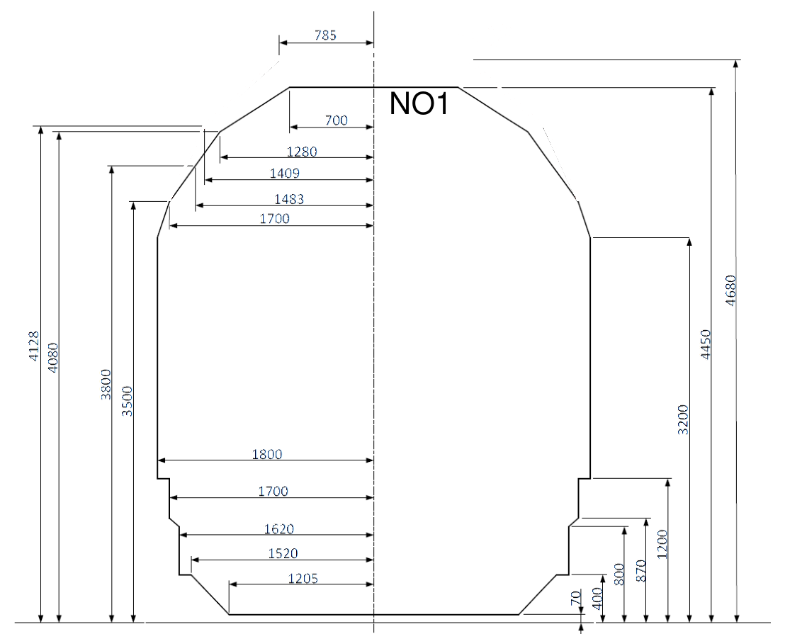
(a) NO1 standard dynamic reference profile.
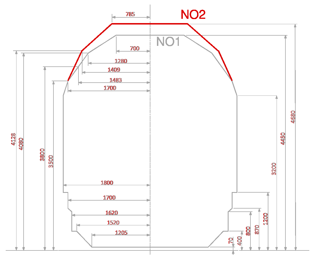
(b) NO2 supplementary dynamic reference profile.
12.1.3 Regulations
The European standard EN 15273 (FprEN 15273, 2025 edition) defines the calculation rules for both rolling stock and infrastructure gauging in five parts: Part 1 (general rules), Part 2 (rolling stock), Part 3 (infrastructure), Part 4 (catalogue of defined gauges), Part 5 (background and worked examples). Bane NOR technical regulations reference EN 15273 and specify the Norwegian gauges that apply to each line.
12.2 Norwegian Structure Gauges
Norwegian structure gauges distinguish between new infrastructure, existing constrained routes, and the rolling-stock profiles each route can accept. The following subsections introduce these categories before linking them to reference and loading gauges.
12.2.1 Gauges for New Lines
New infrastructure is designed with a more generous clearance envelope than many historical lines. The dimensioned new-line profile in Figure 12.1 is the baseline structure gauge before local curve, cant and dynamic allowances are added.
All new lines designed after approximately 1990 use the structure gauge for new lines, which is wider and taller than the historical gauges. This gauge is compatible with the GC freight loading gauge, where GC is a large European/UIC loading gauge for intermodal freight such as ISO containers and semi-trailers. It must also be checked against the passenger rolling-stock profiles approved for the route, the pantograph/catenary envelope, platform interfaces and local restrictions [49].
12.2.2 Gauges for Existing Lines
For an existing route, the first question is an infrastructure question: which obstacle-free cross-section must the line provide? Existing Norwegian lines use a set of historical structure gauges; these are the clearance envelopes for fixed infrastructure, not vehicle profiles. Figure 12.4 compares the structure gauges used for train passage on existing lines.
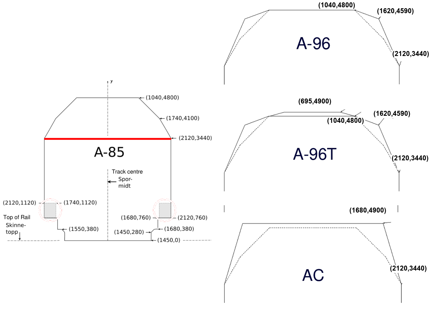
Bane NOR treats A-85 as the basic minimum cross-section for existing lines. A route may additionally be required to satisfy A-96, A-96T, AC (written A-C in the technical regulations) or a snow-plough profile, depending on the traffic the route is intended to carry [49]. The main existing-line profiles are:
- A-85
-
Basic existing-line clearance profile and the smallest of the Norwegian structure gauges.
- A-96
-
Same lower profile as A-85, but with revised upper points for combined transport such as containers and semi-trailers.
- A-96T
-
A top-profile variant of A-96, intended for foreign freight wagons and double-deck passenger vehicles.
- AC
-
Extended existing-line profile for routes that must carry UIC GC traffic.
This subsection is therefore the infrastructure side of the compatibility check. The structure gauge must still be widened or checked for curve overthrow, station-area restrictions, electrification envelopes and local intrusions before vehicles are accepted on a particular route.
12.2.3 From Structure Gauge to Vehicle and Load Profiles
The second question is a vehicle question: which rolling-stock body or freight load can pass through the empty space provided by the infrastructure? In simple terms, the structure gauge is the clear opening that the railway must keep free of obstacles, while the vehicle profile or loading case is the shape that is placed inside that opening during a gauging check. A named loading case is therefore not the actual wagon itself, but a standard envelope representing a wagon plus its load, including the relevant geometric allowances.
The terminology in Table 12.1 is easy to confuse, because it mixes the infrastructure side and the train/load side of the same compatibility check:
- Structure gauge
-
The infrastructure envelope that must be free of fixed objects such as platforms, signals, tunnel walls and electrification equipment.
- Reference profile
-
A standard rolling-stock envelope used in gauging calculations. Norwegian NO1 and NO2 are dynamic reference profiles, as illustrated in Figure 12.3.
- Loading gauge or loading case
-
A standard envelope for a freight wagon and its load. The case says, for example, how high and wide a container, swap body or semi-trailer may be when carried on a specified type of wagon. G1, GA, GB and GC are named European vehicle/load envelopes; GA, GB and GC are mainly used for freight and combined transport, with GC the largest of these three. C/P 410 is a combined-transport code: C means container or swap body, P means semi-trailer, and 410 is the nominal 410 cm height class [40, 53].
- Permitted profile in the table
-
A profile or loading case that is normally compatible with the listed infrastructure gauge. It is a screening result, not automatic route approval.
Bane NOR presents the relationship as a screening table: first identify the infrastructure gauge on the route, then check which vehicle/load envelope is normally intended to fit inside it. Local restrictions, measured route profiles, curve overthrow, pantograph clearance and vehicle simulations still govern the final decision [40].
The table also uses NO1 and NO2 for the Norwegian dynamic rolling-stock reference profiles, and MP for the multipurpose profile for high bi-level wagons or bi-level passenger vehicles where contact-line insulation clearance permits.
| Structure gauge | Vehicle/load envelope tested inside it | Meaning for a route check |
|---|---|---|
| A-85 (existing) | NO1, G1, GA, GB and MP where contact-line insulation permits | Basic existing-line clearance. It may carry ordinary rolling stock and several standard freight profiles, but high or wide vehicles still require local route checks. |
| A-96 (existing) | C/P 410 combined transport | Existing-line gauge with extra upper-corner clearance for selected container and semi-trailer traffic. |
| A-96T (existing) | No separate loading case is listed in Bane NOR's summary table | Top-profile variant of A-96. Use it only with an explicit check of the relevant freight wagon, double-deck passenger vehicle or other vehicle case. |
| AC (A-C, existing) | UIC GC | Existing-line gauge intended for the large GC freight envelope. It still requires route-specific simulation and clearance checks. |
| New-line structure gauge | All listed profiles/loading cases, subject to route approval | Broadest standard infrastructure envelope. It gives the best starting point, but approval still depends on the measured route and vehicle/load case. |
The table is an initial compatibility guide. Final acceptance must be based on the measured route profile and the applicable vehicle, load, curve, platform and electrification checks.
The key idea is therefore a nesting check: the selected vehicle/load envelope must remain inside the infrastructure gauge after the required allowances have been added. If it does not, the route needs restrictions, a different wagon/load case, or physical infrastructure work.
12.3 Curve Overthrow
Curve overthrow is the extra swept space required when a vehicle negotiates a curve. It is a central correction in gauge calculations because the vehicle body no longer remains centred over the track centre line.
12.3.1 Principle
Curve overthrow has two different horizontal components: centre throw at the middle of the vehicle body and end throw beyond the bogie pivots. Figure 12.5 shows the rigid-body chord geometry before the calculation rules are introduced.

A long vehicle in a curve takes more transverse space than on tangent track [65, 124]. The body:
-
swings inward at the midpoint between the bogies (centre throw \(K_i\)), and
-
swings outward beyond the bogies (end throw \(K_y\)).
The structure gauge width must be increased by the curve overthrow at all curved locations, including transition curves and tangent track within a certain distance of a curve [49].
12.3.2 Reference Vehicle
Bane NOR's curve-overthrow tables are based on a reference vehicle with:
-
Total length: 24 m
-
Bogie pivot distance (between bogie centres): 18 m
-
Distance from bogie pivot to car-body end: 3 m
-
Axle distance within the bogie: 2 m
12.3.3 Formulas for Existing Lines (\(R > 180\) m)
For existing lines (gauges A-85, A-96, A-96T, AC) with curve radius \(R > 180\) m, the curve overthrows are:
where \(K_i\) is the centre throw (inside) and \(K_y\) is the end throw (outside). These are conventional-unit expressions: insert \(R\) in metres; the resulting \(K_i\) and \(K_y\) are in millimetres.
For new lines (post-1990), the required width increment is given in tabulated form and includes both the geometric overthrow and the dynamic movements of the vehicle in a single combined value. In station areas on new lines, the curve overthrow is reduced by 80 mm, but the distance from the track centre line must remain at least 2200 mm between heights 760 mm and 3800 mm.
12.3.4 Curve Overthrow in Transition Zones
At locations where the radius changes (transition curves, tangent track near a curve end), the overthrow is interpolated linearly:
where \(L\) is the transition curve length and \(x\) is the distance from the end of the transition curve to the calculation point. Insert \(L\), \(x\), and the constants 10 and 15 in metres; \(K_{ir}\) and \(K_{yr}\) are the full adjacent-curve overthrows in millimetres, so \(K_i\) and \(K_y\) are also in millimetres.
12.3.5 Vertical Curve Overthrow
In vertical curves with radius \(R_v < 1500\) m, a vertical curve overthrow must also be calculated for all heights:
This is a conventional-unit expression: insert \(R_v\) in metres; the constant 27 and the resulting \(K_v\) are in millimetres. The effective clearance dimension is reduced: \(l_i = l - K_v\).
12.3.6 Worked Example: Curve Overthrow
Example: An existing line has a horizontal curve with radius \(R = 500\) m. Calculate the centre throw and end throw for the Bane NOR reference vehicle, and then calculate the reduced overthrow at a point in the adjacent transition zone where \(L = 80\) m and \(x = 30\) m.
Full overthrow in the circular curve:
The structure gauge must therefore be widened by about 81 mm on the inside at the vehicle midpoint, and by about 63 mm on the outside beyond the bogie pivots.
Reduced overthrow in the transition zone:
At this point in the transition zone, the required widening is smaller than in the circular curve, but it is still not zero. The check must therefore use the local value of the overthrow, not only the value in the circular curve.
Vertical curve check: If the same location also has a vertical curve with \(R_v = 1000\) m, the vertical curve overthrow is:
The available vertical clearance dimension is then reduced by approximately 14 mm: \(l_i = l - 14\,\text{mm}\).
12.4 Track Centre Distance at the Reference Point
At the rear of a turnout, the reference point is the clearance cross-section where the swept envelopes of vehicles on neighbouring tracks just cease to conflict. In Bane NOR terminology this is sporets middel; it is not the crossing nose or another turnout component. Figure 12.6 shows the centre-line distance check used at this point: the structure-gauge half-width from one track, the adjacent loading-gauge half-width, construction tolerance and any curve or cant additions must fit between the two track centres [53].
![Reference point (sporets middel) at the rear of a turnout. The vector sketch shows the track-centre distance check; the field photo shows the Bane NOR middelmerke used to mark the point [53, 42].](../../assets/chapters/ch12/original/rendered/fig-track_distance_rp.png)
The reference point (RP, also called the fouling or clearance point; middel) is the location at the rear end of a turnout where the distance between adjacent tracks has become large enough for rolling stock to pass safely. A train standing on the siding or loop must stop before this marker; beyond it, the vehicle envelope may foul the route used by a passing train. Bane NOR specifies that the check is based on the loading gauge on one track, the structure gauge on the other track, a 100 mm clearance, and the relevant curve and cant additions for both tracks [53].
The minimum track centre distance \(S\) at the reference point is:
For the standard case without cant and without curve overthrow:
where 2120 mm is the structure-gauge half-width from track 1 centre line to the structure envelope edge – the half-width of the A-85 profile in its widest height band – and 1700 mm is the half-width of the static loading-gauge envelope used for the vehicle on the neighbouring track, measured from track 2 centre line. Together they represent the minimum space needed from each track centre line to the interface point.
Table 12.2 gives the calculation forms used by Bane NOR for the common straight and curved-track combinations at sporets middel. The table is a calculation checklist for the track-centre distance at the reference point; it does not replace the underlying structure-gauge and loading-gauge checks.
| Track arrangement at the reference point | Distance to check | How to read it |
|---|---|---|
| Straight tracks, or no curve/cant addition needed | \(S\) | Use the base sum of profile half-widths and 100 mm clearance. |
| One track requires outside-curve allowance | \(S + K_y\) | Add the end-throw allowance for the track on the outside of the curve. |
| One track requires inside-curve and cant allowance | \(S + K_i + 2.3h\) | Add centre throw and the cant-related lateral addition for the curved track. |
| One track uses inside-curve allowance and the other uses outside-curve allowance | \(S + K_i + K_y + 2.3\lvert h_2-h_1\rvert\) | Add both curve allowances and the cant-difference allowance between the two tracks. |
| Both tracks require outside-curve allowance | \(S + 2K_y\) | Add the outside-curve end-throw allowance for both neighbouring tracks. |
Here \(K_i\) is the inside-curve centre-throw allowance, \(K_y\) is the outside-curve end-throw allowance, and \(h\), \(h_1\) and \(h_2\) are the cant-related quantities used in the corresponding Bane NOR calculation case. Insert the cant-related quantities in millimetres; the coefficient 2.3 is dimensionless, so its lateral allowance is also obtained in millimetres. If neither track is a through-track (togspor), Bane NOR permits the base value to be reduced to 3720 mm. On new lines where at least one of the two tracks is a through-track, the calculated distance at sporets middel shall not be less than 4000 mm [53].
12.5 Space Required for Moving Vehicles
The previous sections define the nominal gauge envelopes. This section explains how vehicle motion, suspension clearances, cant effects, and curve geometry enlarge the space that must be reserved in practice.
12.5.1 Overview of Influencing Factors
The space a vehicle actually requires in service is significantly larger than its static body profile. The main contributions are:
-
Suspension movements under static and dynamic loading.
-
Failed or degraded suspension components.
-
Eccentric payload.
-
Cant excess or cant deficiency causing the body to tilt inward or outward.
-
Centre throw and end throw (curve overthrow).
-
Cross-wind sway.
-
Wheelset lateral play in the rail (\(\sigma = 27.5\) mm).
-
Bogie-to-wheelset lateral play (\(q = 5\)–\(6\) mm).
-
Car-body-to-bogie lateral play (\(w = 60\)–\(65\) mm).
12.5.2 Horizontal Space Required in a Curve: Inside (Centre Throw)
For the inside of a curve, the clearance calculation adds relative wheelset and bogie displacements, roll due to cant effects, and the centre-throw term. Figure 12.7 identifies these components before they are assembled in the space-required calculation below.
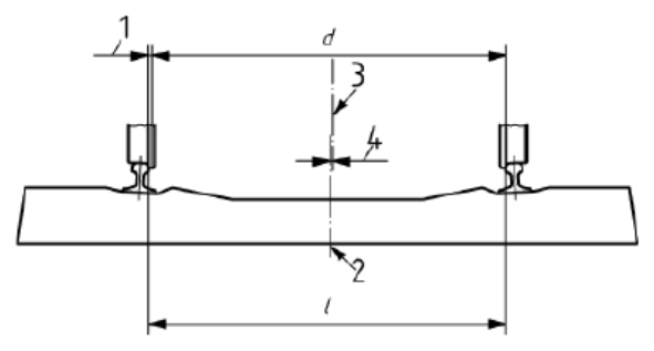
Wheelset to rail play
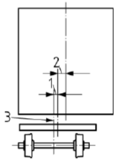
Vehicle body to bogie and
bogie to wheelset play
Superelevation in the track
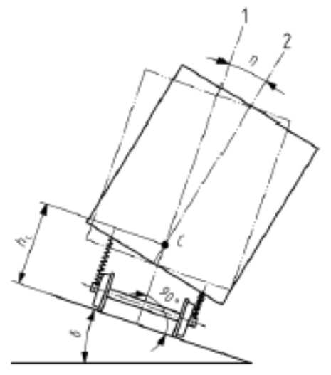
Read Figure 12.7 as three offsets that are added to the vehicle half-width in the formula:
- Wheelset sketch: line 2 is the track centre line and line 3 is the wheelset centre line after the wheelset has shifted toward one rail. The one-sided wheelset play is the difference between the calculation track gauge \(l\) and the wheelset guiding width \(d\), divided by two:
Callout 4 is the horizontal offset between line 2 and line 3; this is the play \(\sigma\). Callout 1 marks the rail-side clearance that limits this shift. The formula therefore adds the term \(A_\sigma\sigma\).
-
Bogie/body sketch: the lateral displacement continues from the wheelset to the vehicle body. Callout 1 gives the bogie-to-wheelset play \(q\), callout 2 gives the car-body-to-bogie play \(w\), and callout 3 is the body side whose clearance is checked. These clearances are added as \(A_q q + A_w w\).
-
Superelevation sketch: callout 1 is the nominal body position and callout 2 is the rolled body position about the roll centre \(c\). Cant deficiency or cant excess creates a small rotation; at the checked height \(h\), the horizontal shift is calculated with the lever arm \((h-h_c)\).
For the cross-section halfway between the bogie pivots on the inside of the curve (vehicle stationary), use the centre-throw geometry \(K_i\) shown earlier in Figure 12.5. The variable \(n_i\) locates the checked cross-section from the nearest bogie pivot toward the vehicle centre, so the curve term below calculates the inward movement at that section. The required half-width is:
where:
-
\(D^{pl}_{i}\) = required lateral space on the inside of the curve, for a cross-section between the bogie pivots (mm)
-
\(A_\sigma = A_q = A_w = 1\) (displacement coefficients, EN 15273)
-
\(\sigma = 27.5\) mm (wheelset-to-rail clearance)
-
\(q = 5\)–\(6\) mm (wheelset-to-bogie clearance)
-
\(w = 60\)–\(65\) mm (car body-to-bogie clearance)
-
\(s = 0.150\)–\(0.225\) (roll angle coefficient)
-
\(D_\text{max} = 150\) mm (maximum cant; 160–180 mm on passenger-only lines)
-
\(D_\text{sup} = 40\) mm (cant supplement due to vertical defects in the track geometry)
-
\(h\) = height of the checked vehicle point above the track plane (mm)
-
\(h_c = 650\)–\(1000\) mm (roll centre height above the track plane)
-
\(R\) = curve radius (mm)
-
\(a\) = bogie pivot distance (mm)
-
\(p\) = axle spacing in the bogie (mm)
-
\(n_i\) = longitudinal distance from the nearest bogie pivot to the checked cross-section, toward the vehicle centre (mm)
12.5.3 Horizontal Space Required in a Curve: Outside (End Throw)
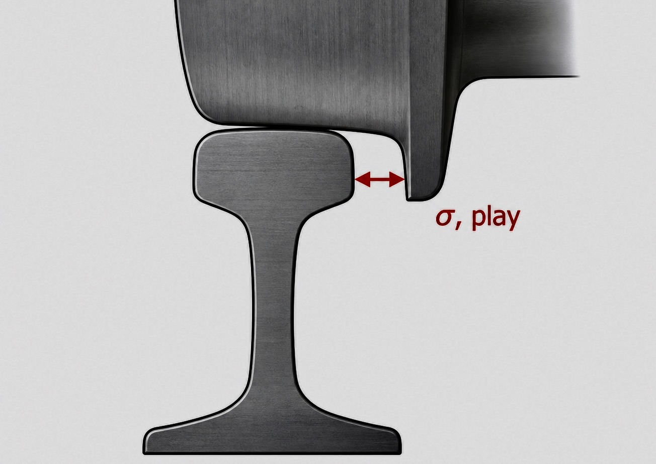
The outside-curve calculation uses the lateral play between wheelset and rails. Norway's nominal track gauge is 1435 mm. The value 1465 mm is the widened calculation gauge used to obtain the maximum lateral play. It is combined with a minimum wheel guiding width of 1410 mm in Bane NOR's rules for track geometry and profiles [18, 53]. The one-sided wheelset-to-rail lateral play is therefore \(\sigma=(1465-1410)/2=27.5\) mm. Figure 12.8 isolates this quantity: the red double-headed arrow marks the one-sided gap between the wheel-flange face and the rail gauge face.
Beyond the bogie pivots on the outside of the curve (vehicle in motion), the displacement coefficients are amplified by a factor \((a + n_a)/a > 1\):
where:
-
\(D^{lp}_{a}\) = required lateral space on the outside of the curve, for a cross-section beyond a bogie pivot (mm)
-
\(\tfrac{a+n_a}{a}\) = amplification factor for relative displacements beyond the bogie pivot
-
\(A_\sigma\), \(A_q\), \(A_w\) = displacement coefficients for wheelset-to-rail, wheelset-to-bogie and bogie-to-car-body movement; the base coefficient is 1, with the end-section amplification applied by \(\tfrac{a+n_a}{a}\)
-
\(\sigma = 27.5\) mm (wheelset-to-rail clearance)
-
\(q = 5\)–\(6\) mm (wheelset-to-bogie clearance)
-
\(w = 60\)–\(65\) mm (car-body-to-bogie clearance)
-
\(s = 0.150\)–\(0.225\) (roll angle coefficient)
-
\(I_\text{max} = 80\)–\(245\) mm (maximum cant deficiency, depending on line curvature and rolling stock)
-
\(I_\text{sup} = 60\) mm (cant-deficiency supplement due to vertical defects in the track geometry)
-
\(h\) = height of the checked vehicle point above the track plane (mm)
-
\(h_c = 650\)–\(1000\) mm (roll centre height above the track plane)
-
\(R\) = curve radius (mm)
-
\(a\) = bogie pivot distance (mm)
-
\(n_a\) = longitudinal distance from the nearest bogie pivot to the checked cross-section, toward the vehicle end (mm)
-
\(p\) = axle spacing in the bogie (mm)
The same geometry in Figure 12.5 is used below: \(n_i\) is used for cross-sections between the bogie pivots, while \(n_a\) is used for cross-sections beyond a bogie pivot.
12.5.4 Horizontal Space Required on Tangent Track
On tangent track, there is no curve overthrow, but the vehicle still sways due to suspension movements and cant deficiency (from track geometry errors). The formula is similar to the curve case but with the static overthrow term set to zero:
12.5.5 Vertical Space Required
Vertical space requirements arise from:
-
Vertical curve overthrow (hump or sag geometries).
-
Spring deflection of primary and secondary suspensions.
-
Wheel-diameter differences due to wear.
-
Eccentric loading causing the body to pitch or sink.
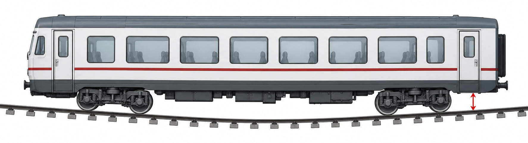
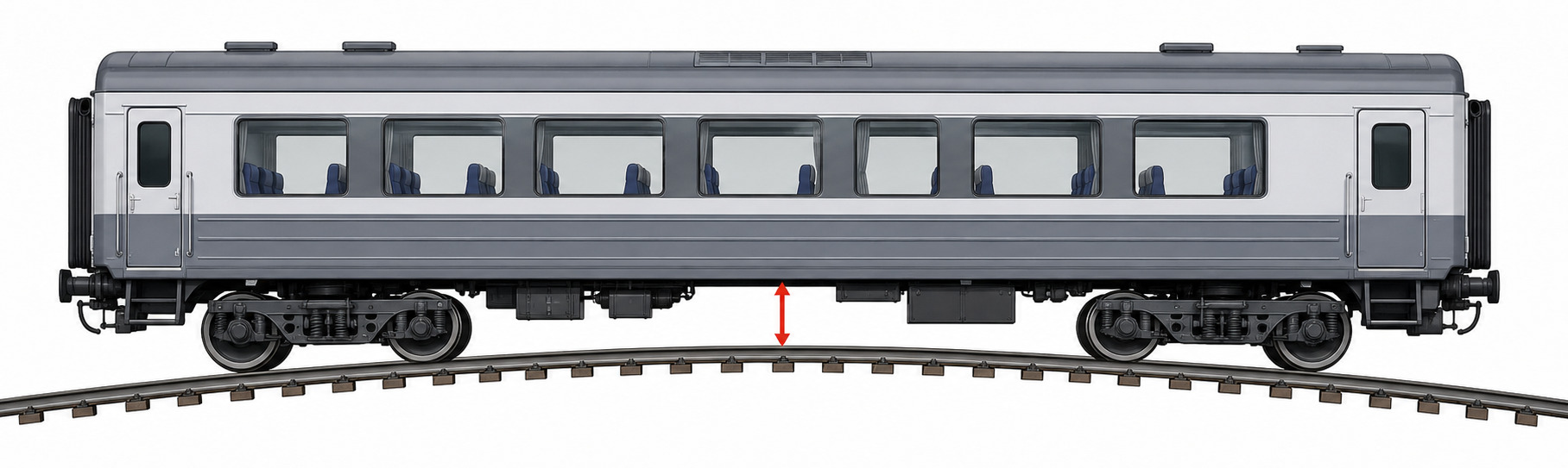
Vertical-curve overthrow is easiest to read by separating the two lower-clearance checks before the formulas. In a concave (sag) vertical curve, the checked lower point can be near the vehicle end beyond the nearest bogie pivot. In a convex (hump) vertical curve, the checked lower point is usually between the bogie pivots, where the vehicle body bridges over the crest. Figure 12.9 compares these two cases visually. The red arrow is drawn from the local track level to the lower vehicle envelope at the checked cross-section; the formulas below then name these two allowances as \(e_a\) and \(e_i\).
(a) Concave sag: end section, ea
(b) Convex hump: centre section, ei
For the sag end case in Figure 12.9(a), the required lower allowance is:
where:
-
\(e_a\) = required vertical allowance for the lower part of the vehicle, at a cross-section beyond a bogie pivot
-
\(\Delta r_w\) = allowance for wheel-diameter difference due to wheel wear
-
\(\Delta h_1\) = primary-suspension deflection
-
\(\Delta h_2\) = secondary-suspension deflection
-
\(f\) = spring deflection due to unfavourable loading
-
\(s = 0.150\)–\(0.225\) (roll angle coefficient)
-
\(I_\text{max} = 80\)–\(245\) mm (maximum cant deficiency, depending on line curvature and rolling stock)
-
\(b\) = distance from the side of the vehicle body to the vehicle centre line
-
\(b_2\) = distance from the secondary suspension to the vehicle centre line
-
\(R_v\) = vertical-curve radius
-
\(a\) = bogie pivot distance
-
\(n_a\) = longitudinal distance from the nearest bogie pivot to the checked cross-section, toward the vehicle end
-
\(p\) = axle spacing in the bogie
For the hump centre case in Figure 12.9(b), the same vertical movement allowances are used, but the vertical curve-overthrow term is based on the distance from the bogie pivot toward the middle of the vehicle:
where \(e_i\) is the required vertical allowance at a lower point between the bogie pivots, and \(n_i\) is the longitudinal distance from the nearest bogie pivot to the checked cross-section. For the centre of the vehicle, \(n_i = a/2\).
12.5.6 Worked Example: Space Required in a Curve
Example: A B7 passenger wagon is checked in a horizontal curve with \(R = 500\) m. The checked upper corner is at \(h = 3500\) mm above the track plane, the roll centre is \(h_c = 1000\) mm, and the half-width of the vehicle body at the checked height is \(b = 1530\) mm. Use:
Outside of the curve, beyond the bogie pivot, vehicle in motion:
The required horizontal distance from track centre line to this point of the vehicle envelope is therefore:
Inside of the curve, halfway between bogie pivots, vehicle stationary:
The corresponding horizontal distance from track centre line is:
The worked example shows why a route check must specify where on the vehicle the calculation is made. The outside end section is governed by amplified relative displacement, cant-deficiency roll and end throw; the inside mid-body section is governed by centre throw and the cant case.
12.6 Platform Clearances and Universal Design
Platform clearance is a special gauging problem because the required gap is both a safety clearance and a passenger-accessibility limit. The curved platform in Figure 12.10 illustrates why the door position on the vehicle matters as much as the curve radius.
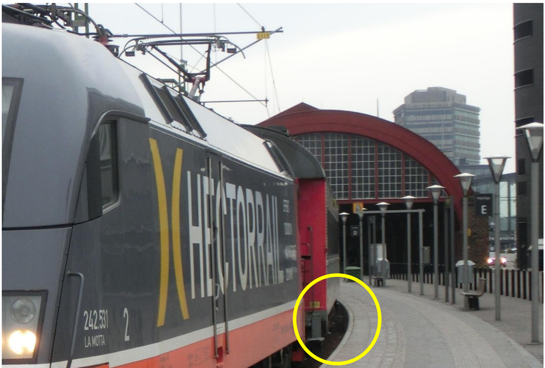
(a) Vehicle and platform-edge gap on the outside of a curve
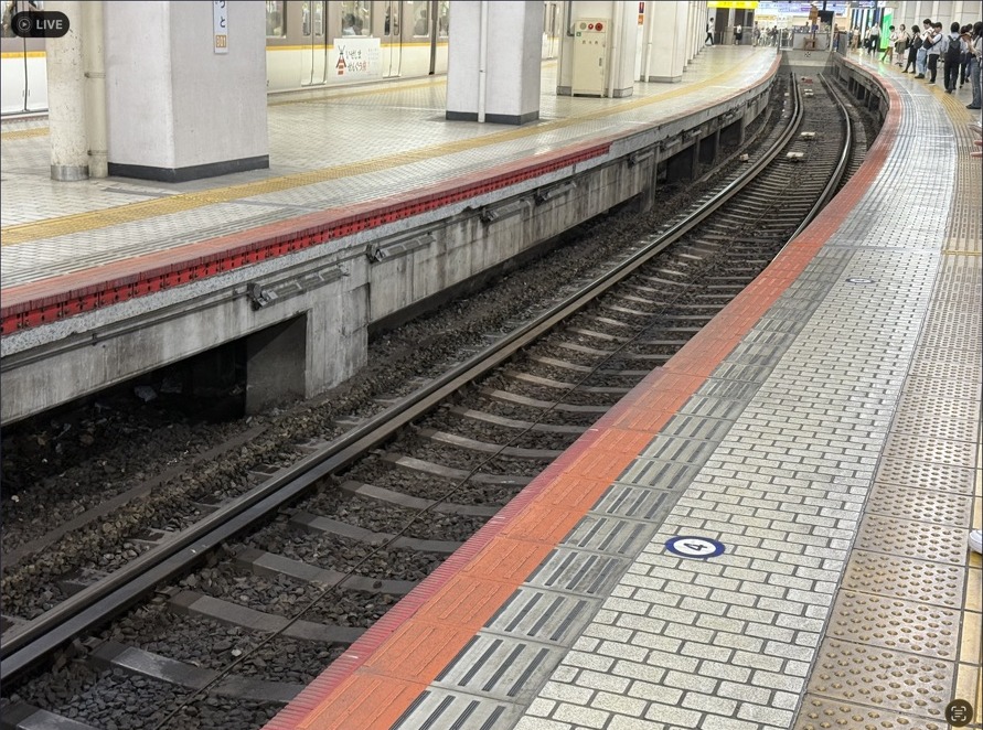
(b) Platform-edge curvature and track alignment in Kyoto
Platform geometry presents the most operationally significant structure-gauge challenge: passengers must step between the platform edge and the vehicle door with a gap that is small enough to be safe and accessible, yet large enough to accommodate the dynamic movements of the vehicle.
For a vehicle in a curve, the centre of the car body shifts inward (centre throw) or outward (end throw) relative to the track centre line. If the platform is on the outside of the curve and the door is near the middle of the car body, centre throw can increase the gap to the platform edge. If the door is near the vehicle end, end throw can instead move the doorway toward an outside platform and reduce the gap. On an inside platform the same centre/end distinction is reversed, so platform checks must use the actual door positions and stopping point rather than a single generic curve correction.
Universal Design requirements (TSI-PRM, Persons with Reduced Mobility):
-
Maximum horizontal platform-edge to footstep gap: 75 mm.
-
Maximum vertical platform-edge to footstep gap: 50 mm.
For the Norwegian FLIRT EMU (Bm 74/75), a minimum curve radius of \(R = 700\) m is required to achieve universal design with a platform on the outside of the curve when the retractable footstep is deployed. In tighter curves, the stepping distance exceeds the universal design limit.
12.7 Structure Gauge Control Methods
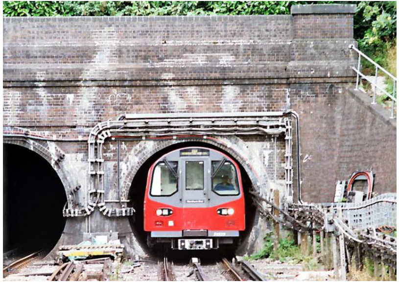
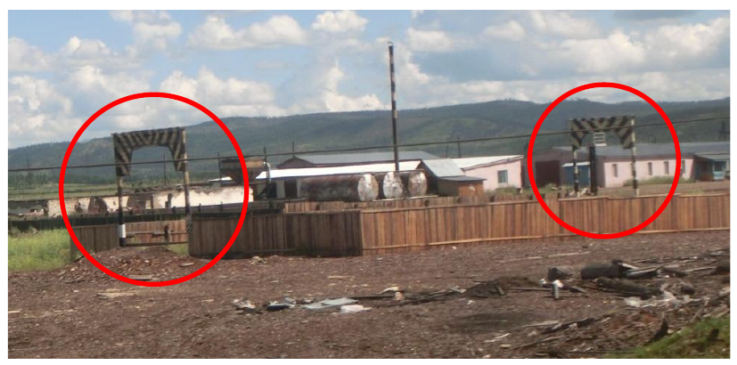
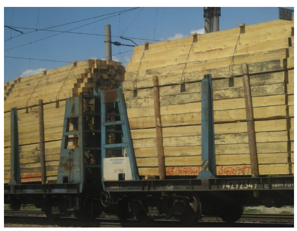
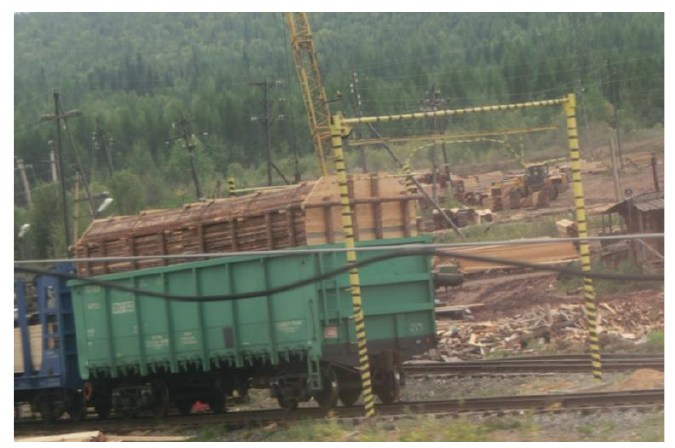
Structure-gauge control combines fixed physical checks with route-wide scanning and simulation. Permanent templates are used in two slightly different ways. At a known clearance restriction, such as a tunnel portal, the template confirms that the local infrastructure clearance is still protected. At loading sites, a loading-gauge frame is a practical go/no-go check before dispatch. Figures 12.11 and 12.12 show the two situations separately.
(a) Loading-gauge frames at a freight site
(b) Timber stacked to fit
the permitted profile
(c) Timber loading frame
Four methods are used to verify and maintain structure gauge clearance:
- Permanent templates
-
Physical gauge frames mounted at fixed locations (tunnel portals, under bridges, loading areas and timber terminals) to check that vehicles and loads remain inside the permitted profile. Simple and reliable, but only valid at the template location.
- Laser scanning
-
A rotating laser mounted on a road-rail vehicle or measuring car scans the track environment at up to 40 000 points per second, with measurement precision of \(\pm 4\) mm and range of up to 70 m. Can scan \(360^\circ\) and operate day or night.
- Sector Profile Scanner (SPS) / measuring gateway
-
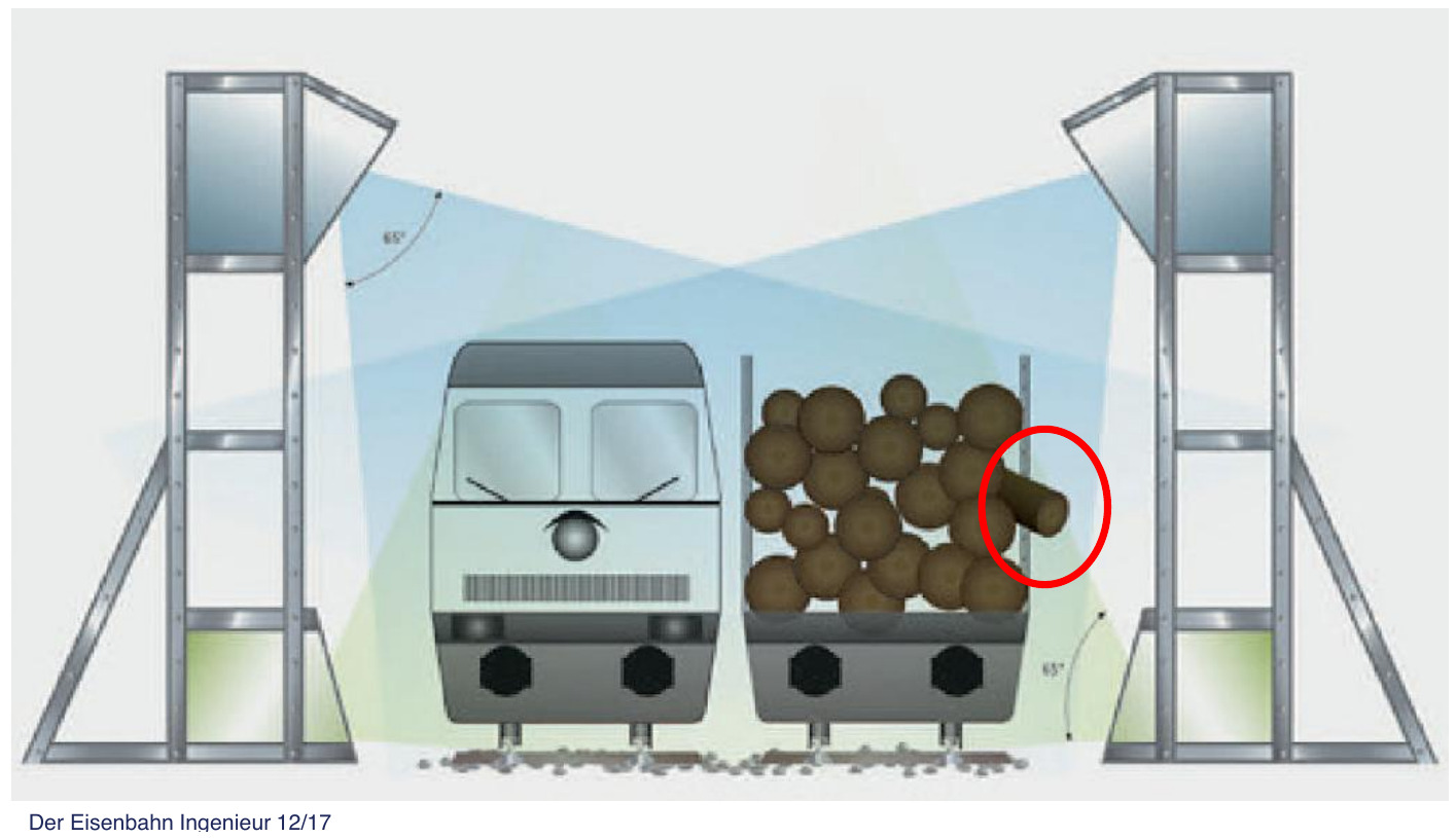
A fixed installation through which trains pass in revenue service, enabling continuous loading-gauge monitoring without a special measuring run. This is useful for loads that can protrude after loading or during transport, such as timber.
- Simulation software (e.g. ClearLoad)
-
Computes the kinematic envelope [65] of new vehicle types on specific lines, used for:
-
Acceptance of new rolling stock.
-
Planning structure gauge enlargements.
-
Special transport authorisation.
-
Cross-section E (pantograph) verification [49].
-
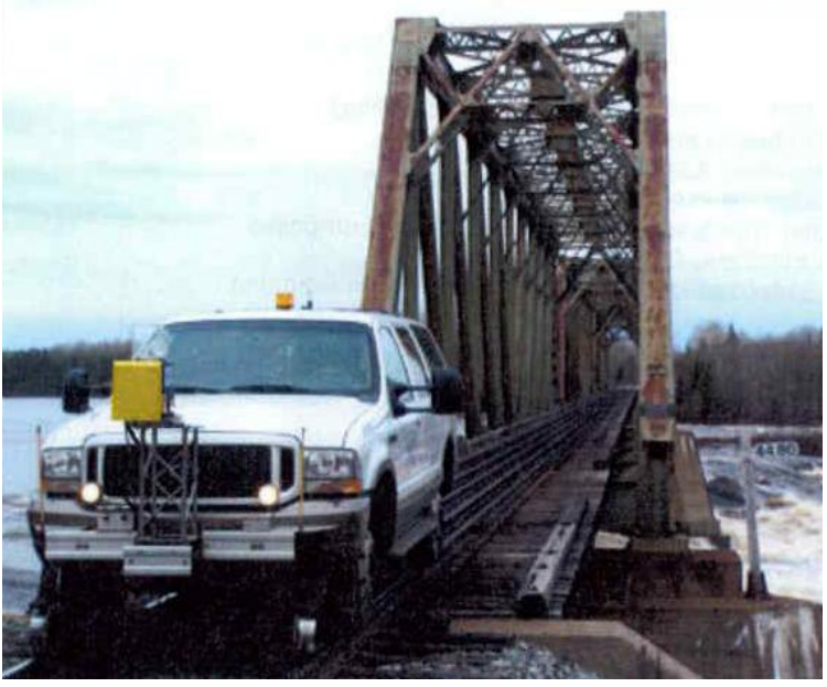
Laser scanning extends the same clearance principle from one fixed location to the whole route. Figure 12.13 shows a structure-gauge control vehicle used for clearance scanning.
A measuring gateway is the fixed-installation equivalent for loading-gauge control in operation. Instead of sending out a dedicated measuring vehicle, the train passes between scanners that compare the actual vehicle and load outline with the permitted profile. Figure 12.14 illustrates this principle for a timber load, where a single protruding log can govern whether the wagon is inside the allowed loading gauge.
12.8 Constraints and Enlargements
Many locations on the Norwegian network have known structure-gauge constraints, particularly in older tunnels and rock cuttings where the cross-section was cut to the minimum required for the gauge standards prevailing at the time of construction. These constraints prevent the operation of modern rolling stock types (e.g. wider freight wagons, bi-level coaches, semi-trailer wagons) on affected sections.
Enlargement options include:
-
Tunnel re-profiling (rock blasting or grinding).
-
Lowering the track formation.
-
Replacing conventional overhead contact lines with rigid rail conductors (electric rail in tunnels), which reduces the pantograph gauge requirement and lowers the required tunnel height.
-
Re-routing (new alignment in the affected section).
New protective structures (snow sheds, rockfall covers) are constructed to the current standard gauge from the outset.
12.9 Chapter Summary
Clearance envelope. The gauge is the boundary inside which fixed infrastructure must not intrude. It must account not only for the static vehicle outline, but also for suspension movement, track tolerances, wheelset play, cant, curve overthrow, construction deviations and maintenance allowances. Gauge design is therefore a clearance problem between vehicle behaviour and infrastructure position.
Gauge profiles. The static profile describes the vehicle at rest, while kinematic and dynamic profiles include movements caused by suspension, curvature, speed and track geometry. A structure that clears a static vehicle may still be unsafe for a moving train. The choice of profile therefore depends on whether the engineer is checking rolling stock, route compatibility, new infrastructure or an existing constrained site.
Curve effects. On curved track, the middle and ends of a vehicle do not follow the same path as the bogie centres. Centre throw and end throw increase the horizontal space required inside and outside the curve, and the effect depends on vehicle length, bogie spacing and curve radius. Transition curves and vertical curves add further variations, so gauge checking must use the local track geometry rather than a single constant clearance.
Platforms and centres. Passenger platforms must be close enough for safe boarding but far enough from the swept envelope of passing trains. Track centre distance must allow two trains to pass with adequate clearance, including dynamic effects and maintenance tolerances. These requirements become more demanding in curves, at high speeds and where existing infrastructure limits the available space.
Gauge control. New lines can meet current gauge requirements from the outset, but existing lines often contain older tunnels, bridges, platforms or rock cuttings with limited clearance. Laser scanning, gauge-control vehicles and route classification help identify where rolling stock is compatible, and where infrastructure modification or operational restriction is required.
Assignments
Assignment 1: Gauge concepts
Before doing calculations, explain the basic gauging terms in words.
(a) Explain the difference between the static loading gauge, the kinematic gauge and the dynamic gauge.
(b) Explain the difference between a vehicle or loading profile and a structure gauge.
(c) Explain why a route check must specify the vehicle point, curve side, operating condition and gauge profile being checked.
Assignment 2: B7 passenger wagon horizontal space requirement
Between 1980 and 1990, NSB purchased the B7 passenger wagons, which are now mainly used on the Bergen line and the Sørland line after refurbishment. Use the following simplified vehicle data:
Use millimetres for every length inserted in the formulas below; \(s\) is dimensionless.
All dimensions to the end of the car body include buffers. The car-body side is slightly arched, but for this assignment check the same half-width at two heights:
The available half-width in the dynamic gauge NO1 at \(h = 3500\) mm is \(B_1 = 1700\) mm. For the structure gauge A-85 at the same height, use the curved-track half-widths \(B_2 = 2175\) mm for the outside/end check and \(B_2 = 2201\) mm for the inside/mid-body check. These A-85 values are obtained by interpolating the tangent A-85 half-width at \(h=3500\) mm and adding the appropriate curve-overthrow widening.
(a) Decide the required space at the upper corner at the end of the car body on the outside of a curve with radius \(R = 350\) m when the car is in motion. Use \(I_\text{max}=160\) mm and \(I_\text{sup}=60\) mm. Check the result against NO1 and A-85.
(b) Decide the required space at the upper corner halfway between the bogies on the inside of the same curve when the wagon is at rest. Use \(D_\text{max}=150\) mm, \(D_\text{sup}=40\) mm and \(n_i=a/2\). Check the result against NO1 and A-85.
(c) A platform is located on the inside of the curve. The available distance from track centre line to the platform edge is 1796 mm, and all trains stop at the platform so the cant term may be taken as zero. Is this distance sufficient for the lower corner halfway between the bogies?
(d) The door edge to be checked is at the lower-corner height \(h_1=500\) mm and is 500 mm inboard from the car-body end, so \(n_{a,\text{door}}=3950-500=3450\) mm. For this door check, ignore relative displacement and cant terms. Calculate the distance from the door to the platform edge and state whether the door moves toward or away from an inside platform.
Assignment 3: Well car vertical space requirement and reference point
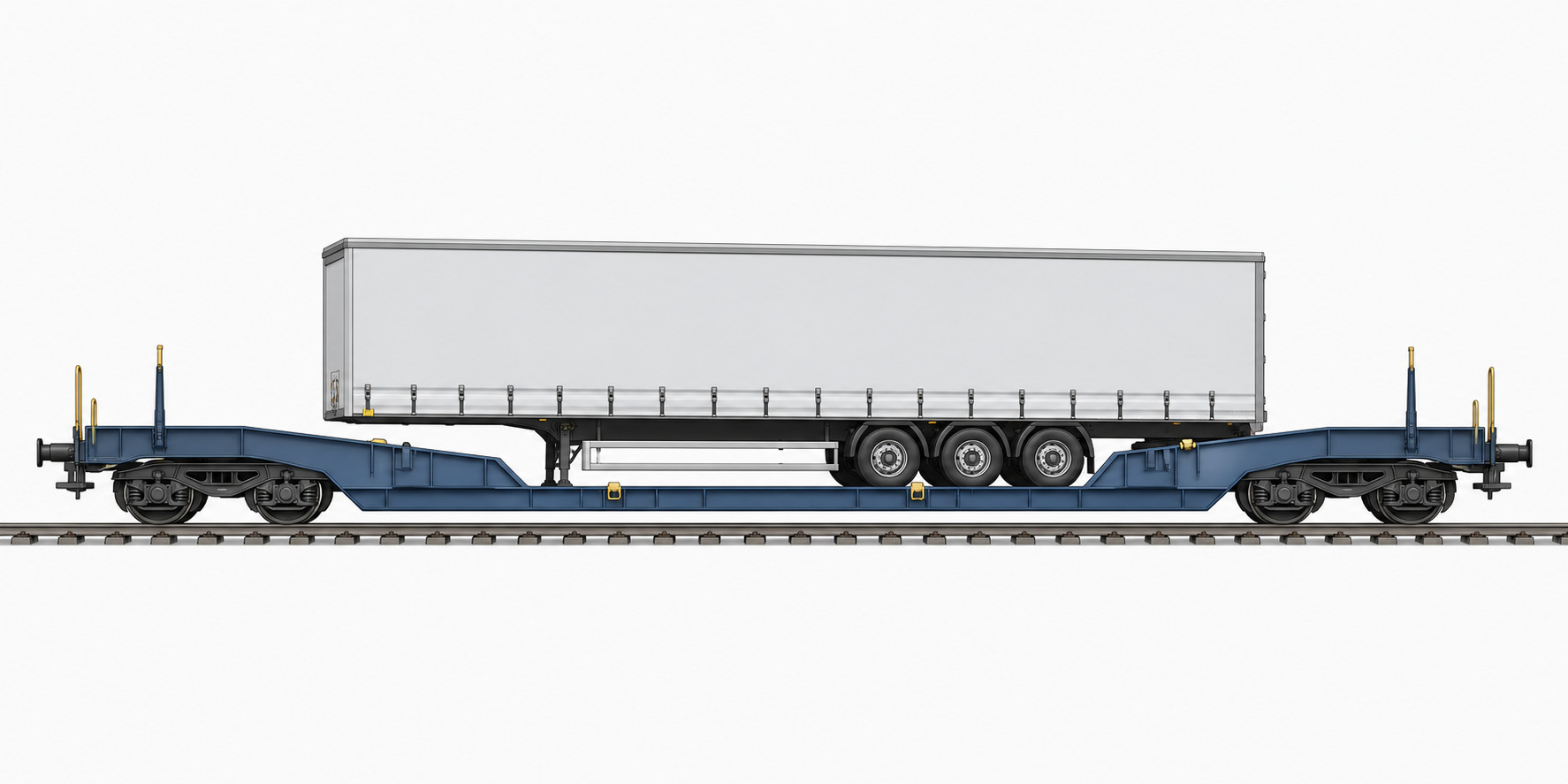
Freight operators use well cars to transport road trailers on a low floor between the bogies. The lowest point of the car is 270 mm above top of rail on tangent track. Check the clearance at the centre of the car in a convex vertical curve with \(R_v = 1500\) m.
Use millimetres for every length inserted in the formulas below; \(s\) is dimensionless.
Use:
(a) Calculate the required vertical allowance \(e_i\) and the remaining clearance to the top of rail at the centre of the well car.
(b) List reasons for dynamic movements of rolling stock and briefly explain how they affect structure-gauge checks.
(c) Explain what a reference point is. How is the track distance at this point calculated?