Ballast
En valgfri KI-generert oversikt. Det skriftlige kapitlet er den autoritative kilden.
3.1 Innledning
Jernbaneballast er laget av knust stein som understøtter svillene, fordeler trafikklastene til undergrunnen og holder sporet i riktig geometrisk posisjon [130, 68, 148]. Det overordnede kravet, som kort sammenfatter alt dette kapitlet forklarer, er:
«Ballastlaget skal være ensartet og bestå av knust stein fra en fast bergart, med en godt gradert blanding av grove korn, kubisk kornform og lavt innhold av fine partikler.»
Følgende terminologi brukes gjennom hele kapitlet for å skille mellom referanser ved skinnenivå, ballastdimensjoner og formasjonsplanet.
| Begrep | Betydning |
|---|---|
| Skinneoverkant laveste skinne (SOK) | Skinnehodets nivå målt på den laveste skinnen; referansenivå for sporgeometrien. |
| Ballasttykkelse | Tykkelsen av ballasten under svillen ned til formasjonsplanet. |
| Ballasthøyde | Overbygningens samlede høyde fra skinneoverkant laveste skinne til formasjonsplanet. |
| Ballastskulder | Ballast utenfor svilleendene; avgjørende for sporets sidestabilitet. |
| Ballast i svillefag (krybbe) | Ballastvolumet mellom to tilstøtende sviller. |
| Formasjonsplan | Klargjort overflate på underbygningen som ballastlaget legges på. |
Den tilhørende konstruksjonstegningen fra teknisk regelverk er vist i figur 3.1. Den er særlig nyttig for å lokalisere formasjonsplanet, øvre og nedre ballastlag og referansen for ballasthøyde som brukes i norsk praksis.
![Ballastprofil fra teknisk regelverk med formasjonsplan, øvre og nedre ballastlag, samlet ballasthøyde og referansenivået 480 mm for skinneprofilene 60E1/60E2. Kilde: Bane NOR [10].](../../assets/chapters/ch03/original/figures_trv/fig3_trv_ballast_profile_layers_enhanced.png)
3.2 Ballastlagets funksjoner
Jernbaneballasten skal samtidig ivareta fire ulike mekaniske og hydrauliske funksjoner [130, 68]:
-
motstå sideveis og langsgående forskyvning av sporet;
-
fordele vertikale hjullaster til formasjonsplanet;
-
sørge for drenering; og
-
gi en viss vertikal ettergivelighet og demping.
Disse funksjonene skal ivaretas samtidig. Dersom én av dem er utilstrekkelig, kan resultatet bli geometrifeil, raskere komponentslitasje og kortere vedlikeholdsintervaller. Avsnittene nedenfor beskriver hver funksjon og hvordan den avhenger av ballastkvaliteten.
3.2.1 Sporets sideveis og langsgående stabilitet
Ballastens viktigste mekaniske oppgave er å motstå sideveis og langsgående krefter som virker på svillene. Sidekrefter fra hjul–skinne-kontakten i kurver og trykkrefter fra temperatur i helsveist spor (CWR) skyver sporet sideveis. Dersom ballastmotstanden er utilstrekkelig, knekker sporet ut sideveis (solslyng) [10]. Ballasten tar også opp langsgående krefter fra bremsing og trekkraft.
Motstanden oppstår gjennom:
-
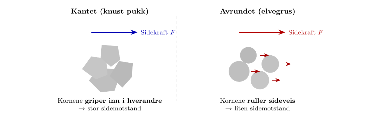
Friksjon mellom kornene i ballastpukken (innbyrdes låsing): Derfor brukes kantet, knust pukk i stedet for avrundet elvegrus. Runde korn ville rulle som kulelagre; kantede korn griper inn i hverandre.
-
Egenvekt: Ballastens høye densitet øker normalkraften og dermed friksjonsmotstanden.
-
Innspenning av svillen: Ballasten omslutter og fastholder svillen på alle sider.
På rett spor er nødvendig bredde på ballastskulderen omtrent 400 mm, mens den er 500–550 mm i krappe kurver. Bane NORs tekniske regelverk angir tre standardprofiler for ballast som funksjon av kurveradius og svilletype (avsnitt 3.4).
Forskjellen mellom egnet, knust ballast og uegnet, avrundet tilslag er vist skjematisk i figur 3.2: Kantede overflater griper inn i hverandre og motstår sideveis svillebevegelse, mens avrundede korn har en tendens til å rulle sideveis under belastning.
3.2.2 Fordeling av vertikallast
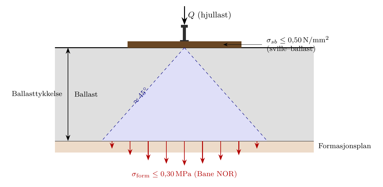
Trafikklastene når ballastoverflaten som konsentrerte krefter under hver sville. Ballasten skal spre disse lastene både sideveis og langsgående. Figur 3.3 viser den tilsiktede lastveien: En konsentrert kraft ved skinnesetet blir til et lavere trykk over et større areal på formasjonsplanet.
De viktigste parameterne som styrer lastfordelingen, er:
-
Ballastkvalitet (korngradering og renhet): Ballastpukk som oppfyller kravene, har en åpen, kontrollert korngradering, kantede korn og lavt finstoffinnhold. Denne kombinasjonen bevarer kornlåsing og drenering samtidig som svillelasten fordeles. Forurensning fyller hulrommene, svekker dreneringen og kornlåsingen og kan konsentrere trykket under deler av svillen med dårlig understøttelse.
-
Ballasttykkelse: Under normale forhold kreves vanligvis omtrent 300 mm under svillen for å oppnå akseptabelt trykk på formasjonsplanet.
-
Svilleavstand: har sekundær betydning; i praksis er avstanden fastsatt til 600 mm i standard spor.
Eisenmann-metoden for beregning av kontaktspenningen mellom sville og ballast er presentert i kapittel 1. Ved foreløpig dimensjonering skilles det vanligvis mellom to grenseflatekontroller:
-
Kontaktspenning mellom sville og ballast (under svilleflaten): Et typisk dimensjoneringsmål er \(\sigma_{sb} \leq 0{,}50\,\mathrm{N/mm^2}\).
-
Spenning mellom ballast og formasjonsplan (ved ballastlagets underside): En vanlig lærebokbasert tommelfingerregel er \(\sigma_\mathrm{form} \leq 0{,}30\,\mathrm{MPa}\). Omtrent 300 mm ren ballastpukk med åpen korngradering i samsvar med kravene under svillen er tilstrekkelig til å redusere vanlige hjullaster til under denne grensen på en bæredyktig undergrunn.
De to grensene gjelder ulike grenseflater og må ikke blandes sammen: Den første begrenser trykket direkte under svillen, mens den andre begrenser spenningen som når formasjonsplanet etter lastspredning gjennom hele ballasttykkelsen. Målte spenninger øverst på en bæredyktig undergrunn i drift er ofte langt lavere, vanligvis i størrelsesorden \(0{,}05\,\mathrm{MPa}\) for ordinær trafikk. Verdien \(0{,}30\,\mathrm{MPa}\) bør derimot forstås som en foreløpig dimensjoneringsverdi for kontroll mot tillatt grense, ikke som en typisk driftsspenning.
3.2.3 Regneeksempel: ballasttykkelse og spenning på formasjonsplanet
Oppgave. En ny strekning har 60E1-skinner og betongsviller og dimensjoneres for \(250\) km/h. Aksellasten er 22,5 t. Anta i en foreløpig kontroll at den sentrale svillen tar 50 % av den dynamiske aksellasten, at den dynamiske forsterkningsfaktoren er 1,4, at svillemålene er \(2{,}60\times0{,}26\) m, og at lasten spres med \(35^\circ\) fra hver svillekant. Avstanden fra SOK til svillens underside er 0,410 m. Beregn spenningen på formasjonsplanet og sammenlign den med en tillatt verdi på 0,25 MPa.
Trinn 1: bestem ballasttykkelsen under svillen. Standard samlet høyde for 60E1-skinne er 0,75 m fra SOK. Fordi dimensjonerende hastighet overstiger 200 km/h, legges 0,05 m til:
Trinn 2: beregn dimensjonerende kraft på svillen. Når akselmassen omregnes til kraft og angitt lastandel og dynamisk faktor anvendes, fås
Trinn 3: beregn effektivt areal på formasjonsplanet. Med tosidig lastspredning i begge planretninger fås
Trinn 4: kontroller spenningen på formasjonsplanet.
Fordi \(0{,}061<0{,}25\) MPa, er den forenklede kontrollen av bærespenningen oppfylt.
Tolkning. Resultatet er et foreløpig overslag basert på lastspredning, ikke en fullstendig dimensjonering av formasjonsplanet. Beregningen forutsetter ren ballast, fast spredningsvinkel, jevnt trykk over det effektive arealet og angitt lastandel på svillen. Nedbrutt ballast, ujevn understøttelse, gjentatt belastning, setninger, frost og drenering må kontrolleres separat. En fullstendig dimensjonering bør også undersøke følsomheten for de styrende dimensjonene og identifisere praktiske utbedringstiltak dersom trykket på formasjonsplanet er uakseptabelt.
3.2.4 Drenering
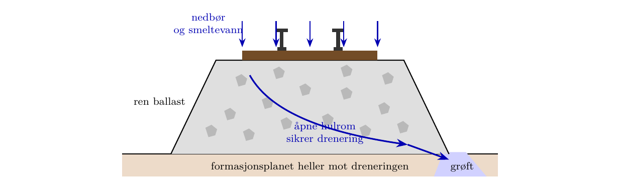
Et velfungerende ballastlag skal lede regnvann og smeltevann fritt bort fra sporet. Drenering krever hulrom mellom kornene. Ballasten må derfor ikke være så tett gradert at hulrommene lukkes, og finstoffinnholdet må forbli lavt. Vann som blir stående i et forurenset ballastlag, reduserer friksjonen mellom kornene og bidrar til oppbløting av undergrunnen. Kombinasjonen av vannmetning og trafikklast gir pumpevirkning: Svillen beveger seg vertikalt og gjør gradvis det fine materialet flytende, samtidig som ballasten knuses mot et hardt underlag.
3.2.5 Elastisitet og demping
Ballastlaget gir en betydelig, ikke-lineær vertikal ettergivelighet og energidissipasjon i det samlede understøttelsessystemet. Betongsviller er langt stivere enn tresviller, men den samlede ettergiveligheten fordeles mellom mellomlegg, sville, ballast, forsterkningslag og undergrunn. Svillematter (kapittel 2) og ballastmatter (avsnitt 3.5) kan brukes for å tilpasse stivheten og dempingen bevisst. Ballastens tilstand og innspenning påvirker derfor både de dynamiske hjul–skinne-kreftene og overføringen av støy og vibrasjoner.
3.3 Krav til ballastmaterialet
Det stilles strenge krav til ballast fordi variasjoner i én enkelt egenskap, som korngradering, kornform, fasthet eller fuktinnhold, medfører differansesetninger, geometrifeil og kortere vedlikeholdsintervaller. Kravene finnes i Bane NORs tekniske regelverk, teknisk spesifikasjon for ballast og NS-EN 13450 (Jernbaneballast) [10, 130, 79]. Når kompendiet brukes til dimensjonering, skal gjeldende utgave og nasjonalt tillegg eller prosjektspesifikasjon kontrolleres.
3.3.1 Ballastgradering og kornfordelingskurve
Den norske produksjonsspesifikasjonen for jernbaneballast (ballastpukk) angir en nominell fraksjon på 31,5–63 mm for ballast i hovedspor, slik Bane NORs tekniske spesifikasjon for ballast fastsetter [10]. Ofotbanen er et unntak, med angitt korngradering 22,4–50 mm i kategori OB. Kornfordelingsområdet er utformet for å:
-
sikre tilstrekkelig hulrom for drenering og elastisitet;
-
sikre tilstrekkelig innbyrdes låsing mellom kornene; og
-
utelukke korn som er for store (fare for svilleskade) eller for små (fare for vandring ned i formasjonsplanet).
Produksjonsgraderingen angir derfor kornfordelingsområdet for den leverte massen, mens laboratoriets prøvingsfraksjon styrer hvordan motstanden mot knusing og slitasje kontrolleres.
| Punkt | Krav | Bruk/merknad |
|---|---|---|
| Nominell størrelse, hovedspor | \(d=31{,}5\) mm,\(D=63\) mm | Standard ballastfraksjon i henhold til NS-EN 13450 og Bane NOR. |
| Nominell størrelse, Ofotbanen | \(22{,}4\)–\(50\) mm | Korngradering i kategori OB, vist i figur 3.4. |
| Kornfordelingskategori | Kategori E | Gjelder ballastprøver både fra sporet og fra transportkjeden. |
| Kategorier for finkorn og finstoff | Finkorn kategori A; finstoff kategori D | Finkorn og finstoff kontrolleres ved sikteanalyse. |
| Prøvingsfraksjon for LA\(_{RB}\) og MDE\(_{RB}\) | \(31{,}5\)–\(50\) mm | Laboratoriefraksjon for prøving av motstand mot knusing og slitasje. |
Sammenheng med prøvingsfraksjoner i EN 13450. Den europeiske standarden NS-EN 13450 definerer prøvingsfraksjoner for standardisert kvalitetsprøving. Slitasjeprøvingene LA\(_{RB}\) og MDE\(_{RB}\) (avsnitt 3.3.4) utføres på delfraksjonen 31,5–50 mm, slik at resultatene kan sammenlignes på tvers av leverandører og land. Denne CEN-fraksjonen er en delmengde av den norske produksjonsspesifikasjonen (31,5–63 mm); de to må ikke blandes sammen. Produksjonsspesifikasjonen styrer hva som leveres til anlegget, mens prøvingsfraksjonen styrer hvordan slitasjemotstanden måles i laboratoriet.
Kornfordelingsområdene er lettere å sammenligne i siktekurven i figur 3.4. Den skiller mellom standardområdet i kategori E for ballast i hovedspor (31,5–63 mm), korngraderingsområdet for Ofotbanen i kategori OB og laboratoriets prøvingsfraksjon 31,5–50 mm, og den framhever den delen av de to korngraderingsområdene som overlapper. Den horisontale aksen viser siktstørrelsen, og den vertikale aksen viser kumulativ masseprosent som passerer sikten: masseandelen som er mindre enn hver siktstørrelse. At 60 % passerer ved 31,5 mm, betyr dermed at 60 % er mindre enn 31,5 mm og 40 % er grovere. Det blå området er standardområdet i kategori E for ballast i hovedspor (31,5–63 mm), det grønne området er Ofotbanens OB-gradering (22,4–50 mm), og det blågrønne området er kombinasjonen av siktstørrelse og passerende masseprosent som oppfyller begge områdene. De røde linjene markerer prøvingsfraksjonen 31,5–50 mm for LA\(_{RB}\)/MDE\(_{RB}\), ikke en korngradering for levert ballast.
![Bane NORs korngraderingsområder og prøvingsfraksjon [10, 79].](../../assets/chapters/ch03/original/figures_gen/fig3_3_banenor_grading_nb.png)
Variasjoner i korngraderingen langs sporet gir differansesetninger og vindskjevhet, selv om alle enkeltprøvene ligger innenfor de godkjente grensene.
3.3.2 Finkorn og finstoff
Bane NOR angir fint materiale med terminologien finkorn kategori A og finstoff kategori D fra NS-EN 13450. Fine partikler fyller hulrommene mellom større steiner og reduserer dreneringskapasiteten og friksjonen mellom kornene. Eldre norsk referansemateriale viser ofte til et nasjonalt kriterium basert på 1,6 mm-sikten. Ved anskaffelse og samsvarskontroll skal gjeldende teknisk spesifikasjon fra Bane NOR følges.
De to EN-begrepene må ikke slås sammen til én «finstoffverdi». Kategorien finkorn styrer materialet som passerer 0,5 mm-sikten, mens finstoff styrer den støvfine fraksjonen som passerer 0,063 mm-sikten. Ved ballastrensing i spor bruker teknisk regelverk en annen vedlikeholdsgrense, basert på den langt grovere nedknuste fraksjonen 0–22,4 mm (avsnitt 3.8.3).
Kilder til fine partikler.
-
Nedbrytning av korn under trafikk: den dominerende langsiktige kilden. Hver akselpassering påfører trykk- og skjærspenninger i kontaktpunktene mellom ballastkornene. Over millioner av lastsykluser sprekker og slites kornene. Sporvedlikehold (pakking) knuser også korn når pakkhakker føres ned.
-
Produksjon og håndtering: Knusing, transport og lagring i hauger genererer finstoff. Hvert prosesstrinn bryter av materiale fra hjørner og kanter.
-
Ytre forurensning: jord som følge av dreneringssvikt, flom- og skredmasser, løvfall, kull- eller malmstøv fra toglast og pollen.
Fine partikler vandrer nedover med regnvannet og samler seg ved bunnen av ballastlaget og på formasjonsplanet. Der tetter de gradvis dreneringsveien. Denne prosessen kalles ballastforurensning. Når hulromsinnholdet nærmer seg null, opphører dreneringen og de mekaniske egenskapene forringes raskt.
3.3.3 Kornform
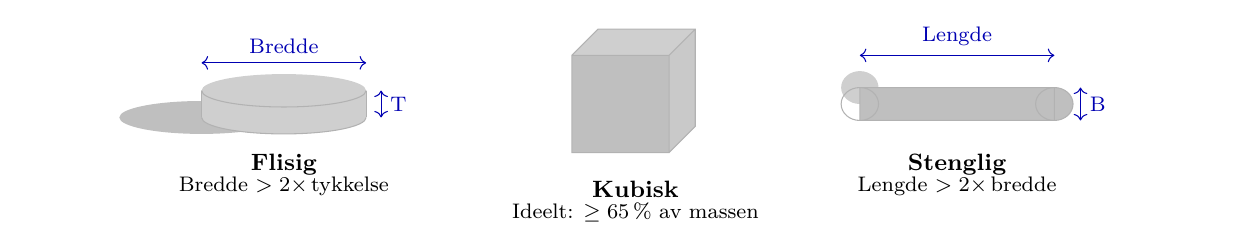
Det ideelle ballastkornet har kubisk form med skarpe, kantede hjørner og ru overflater. Kubiske korn pakker seg godt, gir store kontaktflater for lastoverføring, griper effektivt inn i hverandre og motstår forskyvning under tverrkrefter.
To ugunstige former er definert:
-
Flisig (skiveformet): Kornet er tynt i forhold til målene i planet. Flisige korn har en tendens til å stå på kant etter pakking og deretter legge seg flatt under vibrasjon, slik at det oppstår hulrom og setninger. De har også stor bruddrisiko.
-
Stenglig (stavformet): Kornet er langt i forhold til tverrsnittet. Stenglige korn gir små kontaktflater og har lett for å rulle under belastning.
Figur 3.5 sammenligner disse kornformkategoriene og knytter hver ugunstige form til dimensjonsforholdet som brukes til å gjenkjenne den.
Gjeldende samsvarskontroll.
Gjeldende ballastspesifikasjoner fra Bane NOR viser til EN-prøvingsmetoder og -kategorier, blant annet flisighetsindeks og formindeks, i stedet for den eldre dimensjonssammenligningen 2:1 for «kubiske korn». Beskrivelsen 2:1 er fortsatt nyttig som en kvalitativ forklaring på hvorfor flate og stangformede steiner er uønskede, men anskaffelsesdokumentasjonen skal oppgi de styrende EN-kategoriene i gjeldende teknisk spesifikasjon fra Bane NOR.
Merk at kornformens betydning avtar i de første årene etter utlegging fordi hjørner og kanter brytes av og gjør kornene rundere. Formen blir imidlertid kritisk igjen i siste fase av levetiden, når overflatene er avrundet og ballasten mister evnen til innbyrdes låsing.
3.3.4 Slite- og slagstyrke
Ballast skal motstå knusing og slitasje under gjentatte trafikklaster [128, 130]. To standardiserte laboratorieprøvinger brukes:
Los Angeles-prøving (LA\(_{RB}\)).
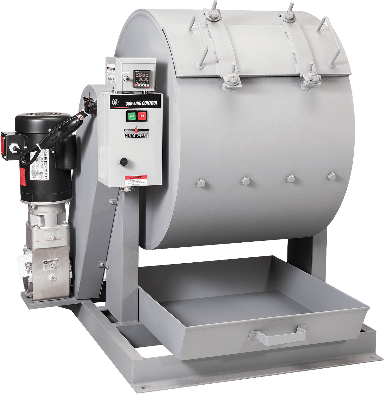
Dette er en tørr trommelprøving: En prøve av fraksjonen 31,5–50 mm roteres i en ståltrommel sammen med stålkuler. Masseprosenten som passerer en 1,6 mm-sikt etter tromlingen, er LA-verdien. En høy LA-verdi viser svak bergart som lett knuses. Jernbaneballast prøves med RB-varianten (Railway Ballast), som bruker den grovere fraksjonen 31,5–50 mm i stedet for fraksjonen 10–14 mm som brukes til vegformål.
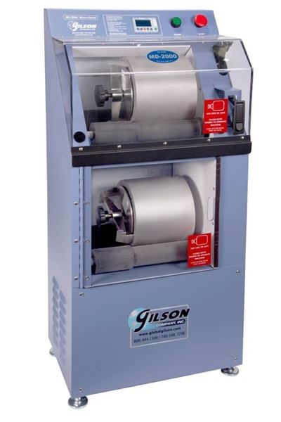
Apparatet består av en roterende ståltrommel. Tilslagsprøven og stålkulene legges i trommelen, trommelen roteres det angitte antallet omdreininger, og det nedbrutte materialet siktes deretter for å bestemme LA\(_{RB}\)-verdien.
Grenser i teknisk regelverk: \(\mathrm{LA}_{RB} \leq 20\) (god: \(\leq 15\)).
Micro-Deval-prøving (MDE\(_{RB}\)).
Dette er en våt trommelprøving uten stålkuler: Prøven roteres i vann for å måle motstanden mot slitasje under våte forhold, som etterligner forholdene i sporet. Også her brukes RB-fraksjonen.
De to prøvingsmaskinene er vist ved siden av hverandre i figur 3.6. Den praktiske forskjellen er tydelig: LA\(_{RB}\)-prøvingen bruker en stor, tørr trommel med stålkuler, mens MDE\(_{RB}\)-prøvingen bruker mindre tromler for våt slitasje.
Grenser i teknisk regelverk: \(\mathrm{MDE}_{RB} \leq 15\) (god: \(\leq 10\)–\(12\)).
Begge prøvingene måler nedbrytning av fraksjonen 31,5–50 mm, som er representativ for utlagt ballast. Til sammenligning prøves tilslag til vegformål på fraksjonen 10–14 mm, slik at resultatene ikke kan sammenlignes direkte.
3.3.5 Kjemiske krav
Ballastkorn inneholder små mengder tungmetaller (arsen, bly, krom og andre stoffer) som forekommer naturlig i alle bergarter. Under normale forhold er disse ikke farlige. Når ballasten knuses av trafikken og de fine partiklene løses opp i vann, kan metallene imidlertid lekke ned i grunnen og grunnvannet. De kjemiske kravene omfatter derfor:
-
største tillatte konsentrasjoner av arsen, bly, krom, kobber og andre tungmetaller, angitt i Bane NORs tekniske spesifikasjon;
-
grenser for polysykliske aromatiske hydrokarboner (PAH), som kan forekomme i forurenset ballast fra eldre strekninger der kreosotbehandlede tresviller var mye brukt.
Ballastavfall som fjernes ved rensing eller utgraving, klassifiseres som næringsavfall etter forurensningsloven. Avfall som oppfyller grensen for rene masser, kan disponeres fritt innenfor rammene av plan- og bygningsloven. Avfall som overskrider grenseverdiene for metaller, skal leveres til godkjent deponi, gjenbrukes på stedet eller selges, avhengig av forurensningsnivået. Ballastavfall må ikke tippes i skråninger eller jernbanefyllinger.
3.3.6 Bergarter
Ballastens mekaniske egenskaper bestemmes først og fremst av moderbergarten. Omtrent 20 ulike bergarter har vært brukt som jernbaneballast i Norge. Granitt og gneis står til sammen for mer enn 50 % av produksjonen fordi disse bergartene er vanlige i norsk geologi [10]. Bergarten påvirker direkte LA\(_{RB}\), MDE\(_{RB}\) og kornformen som oppstår etter knusing. Egnetheten avhenger derfor både av mineralogien og av den mekaniske prøvingsresponsen til den produserte ballastpukken.
| Bergart | Typisk LA\(_{RB}\) | Typisk MDE\(_{RB}\) | Egnethet |
|---|---|---|---|
| Basalt, gabbro, hornfels | \(< 10\) | \(< 8\) | Svært god |
| Amfibolitt, mørk gneis | \(10\)–\(15\) | \(8\)–\(12\) | God |
| Vanlig granitt, grå gneis | \(15\)–\(20\) | \(10\)–\(15\) | Akseptabel (kontroller feltspat) |
| Feltspatrik granitt, syenitt | \(> 18\) | \(> 14\) | Marginal; krever egen prøving |
| Kalkstein, klorittholdig bergart | Ikke relevant | Ikke relevant | Ikke tillatt |
Viktige observasjoner.
Innholdet av feltspat varierer i granitt: Materiale med høyt feltspatinnhold er sprøere og kan nærme seg Bane NORs LA-grense. Klorittholdig bergart er uegnet fordi den fine fraksjonen etter nedbrytning kan virke sementerende, binde kornene sammen og ødelegge dreneringen. Kalkholdig bergart, for eksempel kalkstein, er like uegnet: Kalsiumkarbonat løses langsomt opp i regnvann og danner etter hvert et sementert, ugjennomtrengelig ballastlag [10]. Hver forekomst skal prøves særskilt, uansett bergart, fordi mineralsammensetningen og mikrosprekker etter sprengning varierer mellom ulike deler av steinbruddet.
3.3.7 Oppsummering av materialkrav
Materialspesifikasjonen omfatter ballastgradering, finkorn og finstoff, kornform, slite- og slagstyrke, bestandighet, frostmotstand og petrologisk egnethet.
| Egenskap | Krav fra Bane NOR | |
|---|---|---|
| merknad | ||
| Ballastgradering | Nominell fraksjon 31,5–63 mm ved sikteanalyse | LA\(_{RB}\)/MDE\(_{RB}\) prøves på delfraksjonen 31,5–50 mm. |
| Korngradering på Ofotbanen | 22,4–50 mm, kategori OB | Nasjonalt særtilfelle i Bane NORs spesifikasjon. |
| Finkorn og finstoff | Finkorn kategori A; finstoff kategori D | Følg gjeldende teknisk spesifikasjon fra Bane NOR og terminologien i NS-EN 13450. |
| Kornform | Flisighets-/formkategorier i Bane NORs spesifikasjon | Prøves etter EN-metoder for flisighetsindeks og formindeks. |
| LA-slitasje | LA\(_{RB} \leq 20\) fra Los Angeles-trommelprøving | God ballast har vanligvis verdi \(\leq 15\). |
| MDE-våtslitasje | MDE\(_{RB} \leq 15\) fra våt Micro-Deval-prøving | God ballast har vanligvis verdi \(\leq 10\)–\(12\). |
| Kjemiske grenser | Tungmetaller reguleres av Bane NORs tekniske spesifikasjon; PAH er særlig relevant for gjenbrukt eller forurenset ballast | Særlig relevant for gammel ballast og utgravde masser. |
3.4 Bane NORs tekniske regelverk: ballastprofiler og standardmål
De følgende avsnittene omsetter kravene til ballastmaterialet til standard lagtykkelser, skuldermål og profilvalg som brukes i norsk praksis.
3.4.1 Øvre og nedre ballastlag
Norske ballastspor bygges som et system med to lag, der nedre og øvre ballastlag har ulike funksjoner i byggingen [10]:
-
Nedre ballastlag: legges først opp til et nivå omtrent 480 mm under laveste skinne for 60E1/60E2 og omtrent 440 mm for 54E3/54E4 og mindre skinneprofiler. Laget komprimeres lett uten at materialet knuses. Ved normal drift og normalt vedlikehold forstyrres det ikke; komprimeringstilstanden bevares gjennom hele levetiden.
-
Øvre ballastlag: legges etter at sviller og skinner er montert, ved hjelp av pukkvogner. Dette er det aktive vedlikeholdslaget, og all pakking foregår i dette laget.
Standard samlet ballasthøyde, målt fra SOK til undersiden av ballastlaget, for nye norske spor er [10]:
-
75 cm for spor med UIC60-skinner (60E1 eller 60E2).
-
70 cm for alle andre skinneprofiler.
Høyhastighetslinjer (\(v_\mathrm{dim} > 200\) km/h): Bane NORs tekniske regelverk krever at ballasthøyden økes med 50 mm i forhold til standardverdiene ovenfor. En strekning dimensjonert for 250 km/h med 60E1-skinner krever dermed en samlet ballasthøyde på \(75 + 5 = 80\) cm fra SOK til formasjonsplanet.
Figur 3.7 plasserer disse målene i sportverrsnittet, sammen med SOK-referansen, de to ballastlagene, svillen, skulderen og formasjonsplanet.
![Standard ballasttverrsnitt og system med to ballastlag etter Bane NORs tekniske regelverk [10].](../../assets/chapters/ch03/original/figures_gen/fig3_5_ballast_cross_section_nb.png)
3.4.2 Standard ballastprofiler (skulderbredder)
Bane NORs tekniske regelverk angir tre standardiserte ballastprofiler for tverrsnittsgeometrien. Påkrevd profil avhenger av kurveradius og svilletype (tabell 3.5). En smalere skulder tillates i rett spor og kurver med stor radius; krappere kurver krever bredere skuldre for å ta opp den større tverrkraften.
| Profil | Tresviller | Betongsviller | Min. skulder |
|---|---|---|---|
| Profil 1 | \(r > 500\,\mathrm{m}\) | \(r > 400\,\mathrm{m}\) | \(\approx 400\) mm |
| Profil 2 | \(400 \leq r \leq 499\,\mathrm{m}\) | \(300 \leq r \leq 399\,\mathrm{m}\) | \(\approx 450\) mm |
| Profil 3 | \(300 \leq r \leq 399\,\mathrm{m}\) | \(250 \leq r \leq 299\,\mathrm{m}\) | \(\approx 500\)–\(550\) mm |
Bane NORs tekniske regelverk angir minste ballasttykkelse under svillen. Der svillematter brukes, kan ballasthøyden reduseres med opptil 100 mm, men ballasten under svilleundersiden bør ikke være tynnere enn 200 mm:
-
ordinært ballastert spor: Følg standardprofilet og ballasthøyden som avhenger av skinneprofilet;
-
svillematter med arealspesifikk statisk stivhet \(\leq 0{,}15\,\mathrm{N/mm^3}\) kan begrunne en reduksjon på opptil 100 mm;
-
minste ballasttykkelse under svilleundersiden er 200 mm.
3.4.3 Største ballasttykkelse i kurver med overhøyde
Bane NORs tekniske regelverk angir både minste og største ballasttykkelse i kurver med overhøyde [10]. Ved gjentatt løfting og pakking samler det seg fortrinnsvis ballast under den høye ytterskinnen. Uten en øvre grense for tykkelsen blir skulderen etter hvert asymmetrisk, noe som destabiliserer sporgeometrien.
-
Største ballasttykkelse under svillen ved høy ytterskinne: 700 mm.
-
Største ballasthøyde målt fra skinnehodet: 1 050 mm for skinneprofil 54E3 eller 1 100 mm for skinneprofil 60E1.
Når en av grensene nærmer seg, skal vedlikeholdet redusere ballasthøyden i stedet for å fortsette å løfte sporet.
3.5 Ballastmatter
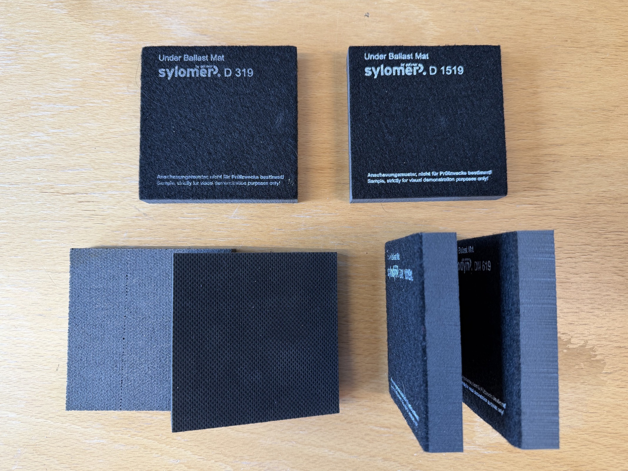
Ballastmatter, som ikke må forveksles med svillematter (USP), er [68, 10] elastiske matter som legges under hele ballastlaget på formasjonsplanet. Hovedformålet er å dempe vibrasjoner, ikke å fordele last. De brukes til å redusere strukturlyd og vibrasjoner som overføres gjennom grunnen til følsomme bygninger i tettbygde områder.
Bane NORs tekniske regelverk angir påkrevd arealspesifikk statisk stivhet \(C_\mathrm{STAT}\) som funksjon av aksellast og driftshastighet (tabell 3.6). Stivhetskravet øker med driftshastigheten fordi raskere tog gir større dynamiske hjulkrefter, og nedbøyningen i matten under hver akselpassering må være liten nok til at sporgeometrien opprettholdes og for store spenningssykluser i skinnen unngås.
| Trafikk-/lasttilstand | Driftshastighet | \(C_\mathrm{STAT}\) [N/mm\(^3\)] |
|---|---|---|
| Aksellast \(\leq 160\) kN | \(v \leq 120\) km/h | \(\geq 0{,}02\) |
| Aksellast 160–250 kN | \(v \leq 120\) km/h | \(\geq 0{,}03\) |
| Alle relevante aksellaster | \(120 < v \leq 200\) km/h | \(\geq 0{,}06\) |
| Alle relevante aksellaster | \(v > 200\) km/h | \(\geq 0{,}10\) |
Den relevante hastigheten er største driftshastighet over strekningen med matte.
Bruksbegrensninger (teknisk regelverk):
-
Ballastmatter skal bare brukes på hard undergrunn og i tunneler. De er uten virkning, og kan være skadelige, på myk undergrunn.
-
Ballastmatter skal ikke brukes sammen med svillematter (USP) eller XPS-isolasjonsplater. Kombinasjonen kan gi ugunstig resonans og for stor nedbøyning under last.
Produktprøvene i figur 3.8 viser hvorfor ballastmatter spesifiseres etter både stivhetsklasse og tykkelse. I sporet legges samme type materiale sammenhengende under ballastlaget.
3.6 Produksjon, transport og håndtering
Ballastkvaliteten avhenger av moderbergarten og av hvordan tilslaget knuses, transporteres, lagres og prøvetas før det når sporet.
3.6.1 Produksjon
Jernbaneballast produseres ved flertrinnsknusing av berg fra steinbrudd [79, 10]. Figur 3.9 oppsummerer hele kjeden fra steinbrudd til spor, mens de viktigste produksjonstrinnene er:
-
Primærknusing: Store, sprengte bergblokker reduseres til en grovere fraksjon.
-
Sekundærknusing og tertiærknusing: Etterfølgende passeringer gir ønsket størrelsesområde og forbedrer kornformen ved å fjerne svakt materiale med mikrosprekker fra sprengningen.
-
Sikting: Uønskede fraksjoner skilles ut etter hvert knusetrinn. Den godkjente fraksjonen, 31,5–63 mm etter Bane NORs spesifikasjon, legges i lagerhaug.
Hver ekstra knusepassering forbedrer kornformen, som blir mer kubisk, og fjerner svake korn, men øker finstoffinnholdet. Fallhøyden fra sikten bør ikke overstige 4 m for å begrense nedbrytning øverst i lagerkjeglen.
![Skjematisk produksjonskjede for ballast fra steinbrudd til utlegging. Figuren oppsummerer knusing, sikting, lagring og kvalitetskontroll som er nødvendig for å oppfylle kravene til ballast fra Bane NOR og EN 13450 [10, 79].](../../assets/chapters/ch03/original/figures_gen/fig3_6_ballast_production_flow_nb.png)
Knuse- og siktesløyfen er vist mer detaljert i figur 3.10. Overkorn føres tilbake til en ny knusepassering, mens finstoff og uegnet materiale avvises i stedet for å føres til lagerhaugen.
![Detaljert flyt for flertrinnsknusing og sikting i et steinbrudd for ballastproduksjon. Godkjent fraksjon 31,5–63 mm føres til ren lagerhaug, overkorn returneres til videre knusing, og finstoff eller uegnet materiale tas ut av ballaststrømmen [10, 79].](../../assets/chapters/ch03/original/figures_gen/fig3_7_ballast_crushing_flow_v2_nb.png)
Segregering i lagerhaug.
Når ballast tippes på en konisk lagerhaug, ruller de største kornene ut mot kanten, mens finstoffet konsentreres i midten. Ved bunnen av haugen samler det seg finstoff som regnet har vasket ned. For å begrense virkningene av segregering:
-
dekk lagerhaugene for å hindre utvasking med regnvann;
-
unngå å hente materiale fra de nederste 20–30 cm av haugen;
-
unngå å kjøre hjullastere over toppen av haugen, fordi dette knuser materialet.
Det mest effektive tiltaket er å vaske ballasten i et vaskeanlegg før den forlater steinbruddet.
3.6.2 Transport og håndtering
Under transport med lastebil eller tog får kontinuerlige vibrasjoner de fineste partiklene til å synke ned på gulvet i kjøretøyet. Deretter blir de liggende på bakken når lasten tippes og danner en finstoffrik rest som kan bli blandet inn i neste last. Korngraderingen i levert ballast varierer derfor mellom billass, selv når massene kommer fra samme produksjonsparti i steinbruddet.
3.6.3 Kvalitetskontroll
Kvalitetsprøving utføres både i steinbruddet som produksjonskontroll og på levert materiale i sporet. Følgende regler gjelder:
-
Prøver til produksjonskontroll skal tas tilfeldig, med faste intervaller, vanligvis for hver 2 500 m\(^3\) produsert masse eller med intervall på 1 uke for korngradering, fra tilfeldig valgt materiale og aldri fra visuelt «rene» områder. Produksjonskontrollen er hovedgrunnlaget for å dokumentere samsvar i steinbruddet.
-
Målrettede kontrollprøver kan tas når det foreligger mistanke om et problem. Ifølge Bane NORs tekniske spesifikasjon kan alle prøver brukes som grunnlag for å avvise ballastmasser som ikke oppfyller kravene.
3.7 Ballastforurensning og nedbrytning
Når ballasten er satt i drift, endres egenskapene gradvis fordi hulrom fylles, korn brytes ned og dreneringskapasiteten reduseres.
3.7.1 Forurensningsmekanisme
Fine partikler samler seg over tid i hulrommene i ballasten. Prosessen akselererer gjennom følgende kretsløp:
-
Finstoff som oppstår tidlig i levetiden som følge av knusing og transport, begynner å fylle hulrommene.
-
Trafikklastene sliper kornene i kontaktpunktene og genererer mer finstoff.
-
Pakking for å korrigere geometrien løsner den komprimerte ballasten; ny komprimering sliper kornene ytterligere.
-
Regnvannet vasker finstoffet nedover. Det samler seg ved ballastlagets underside og tetter dreneringsveien.
-
Når dreneringen begrenses, øker vanninnholdet. Vått finstoff reduserer friksjonen mellom kornene, og ballasten mister stabilitet.
-
Geometrifeilene vokser raskere. Hyppigere pakking akselererer forurensningen og skaper et selvforsterkende samspill.
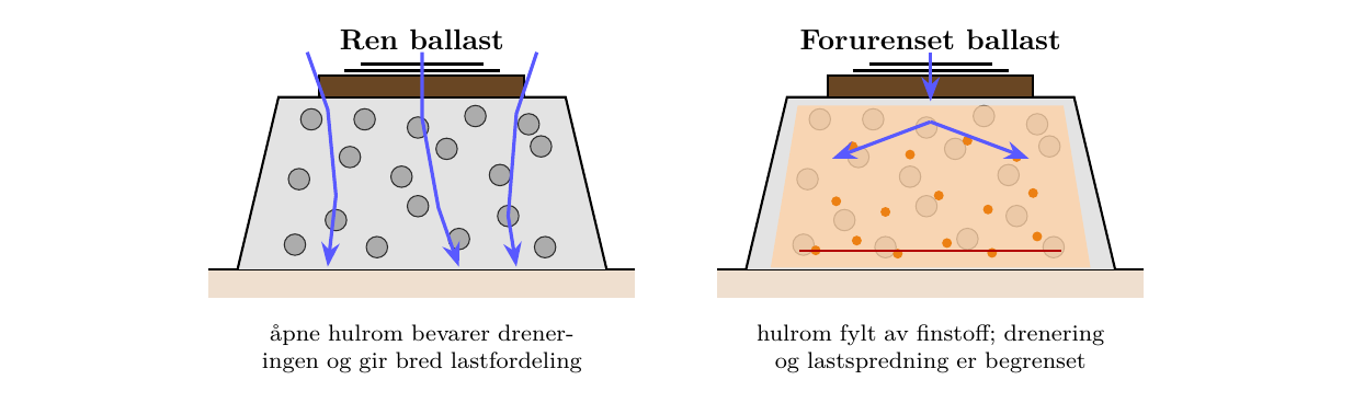
Den mekaniske endringen er vist i figur 3.11: Ren ballast bevarer åpne hulrom for drenering og lastspredning, mens finstoff fyller disse hulrommene i forurenset ballast.
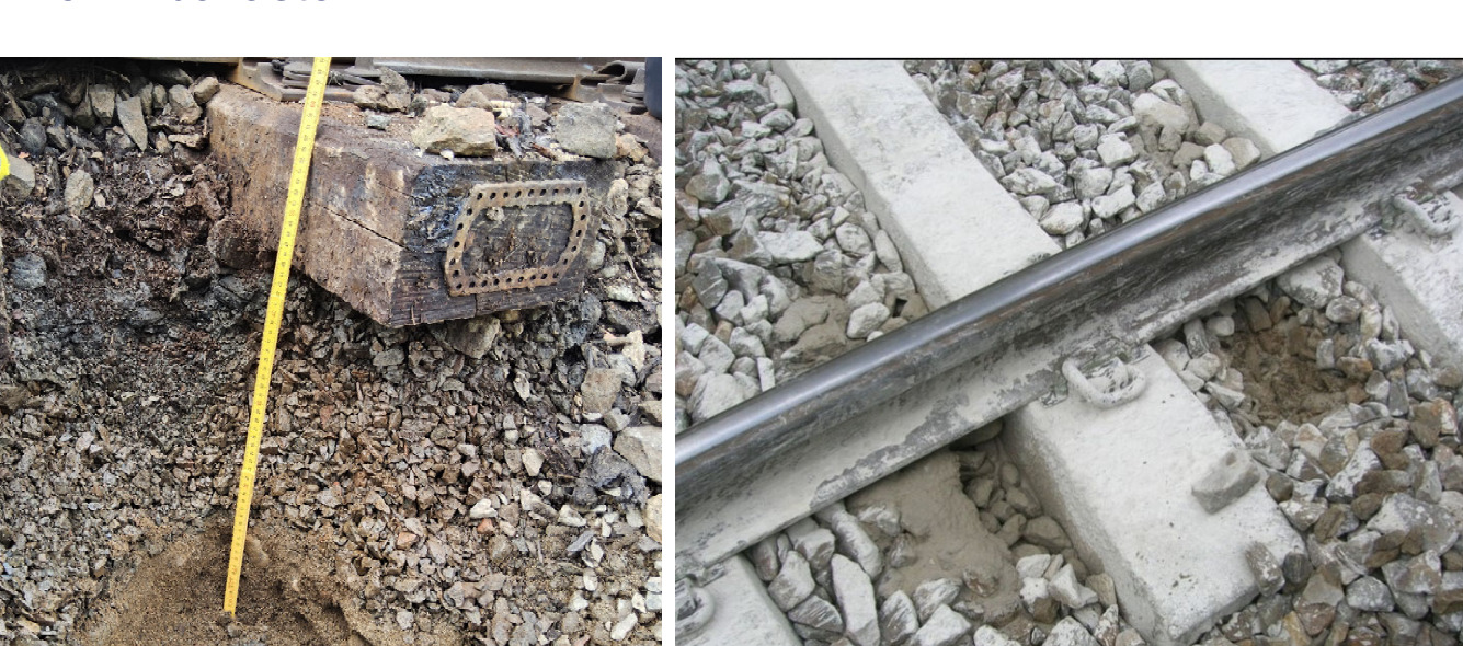
Feltbildene i figur 3.12 viser hvordan dette kan se ut i praksis, med finstoff samlet både under svillen og i svillefaget.
3.7.2 Konsekvenser av ballastforurensning
Forurensningen påvirker flere sporfunksjoner samtidig. Konsekvensene bør derfor forstås som et sammenhengende sett, ikke som isolerte feil.
-
Redusert drenering: Vann som blir stående i ballasten, bidrar til oppbløting av undergrunnen og telehiv.
-
Redusert sidemotstand: Våt, forurenset ballast har sterkt redusert skjærfasthet; faren for solslyng øker.
-
Setninger og geometrifeil: Forurenset ballast komprimeres ujevnt og gir lokale høydeavvik og vindskjevhet.
-
Vaskesviller: Under våte forhold beveger svillen seg i en slamblanding av fine partikler og knuses mot et hardt underlag når forholdene er tørre.
Den ønskede dreneringsveien er skissert i figur 3.13: Vannet passerer gjennom de åpne hulrommene i ballasten og ledes mot dreneringen langs linjen i stedet for å bli stående under svillen.
3.8 Ballastvedlikehold
Vedlikeholdsbeslutningene skal gjenopprette geometri og drenering uten unødvendig å forstyrre ballast som fortsatt fungerer tilfredsstillende.
3.8.1 Rutinemessig vedlikehold
Et ballastlag som ligger uforstyrret, har stabil drenering og jevn trafikkbelastning, kan være funksjonsdyktig i 30–40 år med få inngrep utover:
-
vegetasjonsrydding for å hindre at røtter vokser inn i ballasten;
-
etterfylling av ballast etter pakking som reduserer ballasthøyden.
I praksis forstyrrer lokale inngrep, som kryssinger for signalkabler og reparasjon av drenering, ballasten og reduserer komprimeringen lokalt. Den resulterende geometrifeilen sprer seg når sporet pakkes gjentatte ganger, fordi hver syklus reduserer ballastens densitet og innbyrdes låsing ytterligere.
3.8.2 Pakking
Ved pakking løftes sporet til prosjektert linjeføring, og vibrerende pakkhakker føres ned i ballasten på begge sider av hver sville. Materialet presses inn under svillen slik at den understøttes på nytt. Dette avsnittet beskriver pakking ut fra ballastens funksjon. Den fullstendige vedlikeholdsoperasjonen behandles i kapittel 17, avsnitt 17.5, mens pakkmaskiner, dynamiske sporstabilisatorer og tilhørende produksjonsutstyr beskrives i kapittel 5, avsnitt 5.4. Pakking gjenoppretter geometrien effektivt, men:
-
løsner den komprimerte ballasten, som må sette seg på nytt under trafikk;
-
genererer mer finstoff når pakkhakkene kommer i kontakt med ballastkornene; og
-
konsentrerer deformasjonen i overgangssonene ved hver ende av den pakkede strekningen dersom en kort strekning pakkes gjentatte ganger.
God praksis er å pakke lengre strekninger, legge inn et beregnet overløft for å kompensere for forventet ettersetning og følge pakkingen med dynamisk sporstabilisering (DTS) for å framskynde rekomprimeringen.
Dynamisk sporstabilisering (DTS).
En DTS-maskin klemmer fast skinnene og påfører en kontrollert sideveis vibrasjon, vanligvis ved 30–35 Hz, kombinert med en vertikal statisk last. Vibrasjonen mobiliserer ballastkornene som nettopp er forstyrret, slik at de setter seg i en tettere konfigurasjon med bedre innbyrdes låsing. Dermed gjenskapes komprimeringsvirkningen som ellers ville ha krevd flere hundre tusen bruttotonn trafikk. Bane NORs tekniske regelverk krever dynamisk sporstabilisering etter pakking på nytt eller fornyet spor og på alle strekninger der geometrien forventes å forringes raskt etter pakking. DTS bringer sporets sidemotstand nær verdien før pakking og reduserer dermed faren for solslyng i perioden mens ballasten setter seg på nytt [10].
3.8.3 Forurensningsindeks og Bane NORs kriterium for rensing
Bane NORs kriterium for ballastrensing.
Bane NORs tekniske regelverk (Overbygning/Vedlikehold/Ballast) angir den objektive grenseverdien som utløser ballastrensing [10]:
«Ballastrensing bør utføres når prøving viser at materiale i fraksjonen 0–22,4 mm utgjør mer enn 30 % av prøvens samlede masse.»
På Ofotbanen, med tung malmtrafikk og svært høye aksellaster, gjelder et strengere kriterium: Rensing bør utføres når fraksjonen 0–16 mm overstiger 18 % av prøvens masse.
Grensen på 30 % er enkel å bruke: En standard sikteanalyse av en prøve tatt ut av sporet gir andelen materiale som passerer 22,4 mm-sikten. Når denne fraksjonen når 30 %, er dreneringsfunksjonen alvorlig svekket, og rensing bør planlegges og vurderes sammen med geometrisk kvalitet, dreneringstilstand og trafikkbelastning.
Forurensningsindeks (FI) brukt i forskning.
Forurensningsindeksen (Fouling Index, FI), definert av Selig & Waters (1994), er mye brukt i internasjonal forskningslitteratur:
der \(P_{4}\) er masseprosenten som passerer 4,75 mm-sikten (nr. 4), og \(P_{0{,}075}\) er masseprosenten som passerer 0,075 mm-sikten (nr. 200). FI har ingen fysisk enhet; det er en dimensjonsløs indeks som beregnes fra to sikteresultater angitt i masseprosent. Fordi begge inngangsverdiene er prosentandeler, omtales FI av og til uformelt i prosent, men i dette kompendiet oppgis den som en indeksverdi. Dersom for eksempel \(P_{4}=12\,\%\) og \(P_{0{,}075}=3\,\%\), blir FI = \(15\). Dersom \(P_{4}=36\,\%\) og \(P_{0{,}075}=4\,\%\), blir FI = \(40\). Ren ballast har FI \(< 1\); moderat forurenset ballast har vanligvis FI = \(10\)–\(20\), mens sterkt forurenset ballast kan overstige FI = \(40\).
Selig–Waters-indeksen er ikke kriteriet i teknisk regelverk. Den bygger på andre siktstørrelser, amerikanske standardsikter i stedet for det norske skillet ved 22,4 mm, og ble utviklet for nordamerikanske godsbaner. Indeksen er nyttig for relative sammenligninger og forskningsformål, men må ikke blandes sammen med Bane NORs grenseverdi i teknisk regelverk.
3.8.4 Ballastrensing
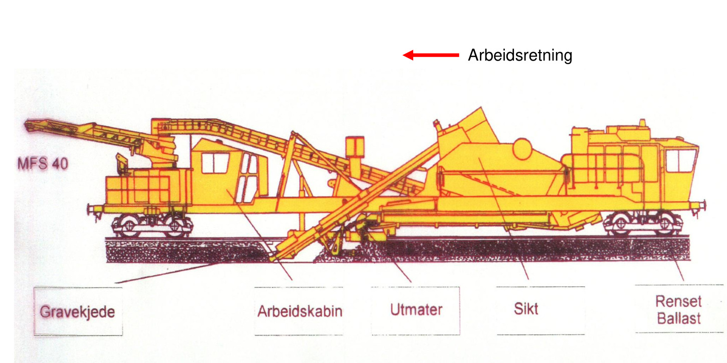
Når ballasten er sterkt forurenset, kan geometrien ikke lenger opprettholdes ved pakking, og sporet må renses. En ballastrensemaskin graver ut ballasten under svillene mens sporet holdes på plass, fører massene gjennom en vibrerende sikt som skiller finstoff fra gjenbrukbar stein, og legger den rensede ballasten tilbake under svillene. Ny ballast tilføres for å erstatte det avviste finstoffet. Figur 3.14 viser materialstrømmen gjennom maskinen: utgraving, sikting, tilbakeføring av gjenbrukbar ballast og borttransport av avvist finstoff.
Maskinen er følsom for forurensningsgraden: Svært sterkt forurenset eller vannmettet ballast reduserer framdriften. Ballastrensing bør ikke utføres i svært vått vær. Ukjente eller store gjenstander under sporet, som gamle sviller, XPS-plater eller grunne stikkrenner, kan skade maskinen.
Feltundersøkelse: georadar (GPR).
Georadar (GPR) brukes av Bane NOR til vurdering av ballast på nettnivå. Georadaren sender korte elektromagnetiske pulser inn i sporet og registrerer tiden det tar før refleksjoner returnerer fra grenseflater mellom materialer med ulik dielektrisk konstant. Ren, tørr ballast har lav dielektrisk konstant (\(\varepsilon_r \approx 3\)–\(5\)) og gir svake, diffuse refleksjoner. Forurenset eller våt ballast har betydelig høyere dielektrisk konstant; fuktighet og leirholdig finstoff øker \(\varepsilon_r\) til 10–30. Dette gir en sterk, tydelig refleksjon ved svillebasen og inne i ballastlaget. Georadarmålinger fra en målevogn i linjehastighet kan lokalisere soner med forurenset eller vannmettet ballast over lange avstander. Dermed kan de fysiske, prøvebaserte målingene etter kriteriet i teknisk regelverk (avsnitt 3.8.3) plasseres målrettet for å bekrefte om grensen for rensing er nådd.
3.8.5 Disponering av ballastavfall
Ballastavfall fra rensing eller utgraving reguleres som næringsavfall. Gjenbruk i prosjektområdet krever en miljørisikovurdering og skal oppfylle gjeldende krav til forurensningskontroll. Forurenset materiale skal sendes til godkjent mottak. Ballastavfall må ikke legges igjen som utvidelse av skråningen, tippes i grøfter eller plasseres i naturterreng, fordi utlekking av metaller kan forurense jord og grunnvann.
3.9 Oppsummering
Funksjon i sporkonstruksjonen. Ballasten understøtter svillene, fordeler vertikallastene, gir sideveis og langsgående motstand, muliggjør drenering, bidrar til demping og gjør det mulig å korrigere sporgeometrien ved pakking. Disse funksjonene avhenger av at steinene forblir kantede, rene, sterke og godt låst inn i hverandre. Når ballasten mister innbyrdes låsing eller dreneringskapasitet, blir sporet raskt mer utsatt for setninger og forringelse av geometrien.
Materialkvalitet. Ballastens gradering, innhold av finkorn og finstoff, kornform, flisighet, slite- og slagstyrke og kjemiske bestandighet påvirker alle egenskapene under gjentatt trafikkbelastning. Ballastpukk som er for svak, brytes ned under trafikk og pakking, mens for avrundede eller dårlig graderte korn gir svakere innbyrdes låsing. Materialprøving er derfor en teknisk kontroll av det framtidige vedlikeholdsbehovet, fremfor en ren formalitet ved anskaffelsen.
Ballastprofil. Ballastlaget skal ha tilstrekkelig tykkelse og skulderbredde til å fordele lastene og motstå sideveis sporbevegelse, særlig i kurver og helsveist spor. Systemet med to ballastlag og standardkravene til skuldrene sikrer at svillen er tilstrekkelig innspent, og at formasjonsplanet beskyttes mot for store spenninger. Dersom ballasttykkelsen eller skulderstøtten er utilstrekkelig, blir sporets stabilitet og geometriske kvalitet følsom for forholdsvis små forstyrrelser fra trafikk eller vedlikehold.
Drenering. Ren ballast er gjennomtrengelig, men fine partikler, oppumping av finmateriale, nedbrutt tilslag og tette grøfter reduserer vannstrømmen. Vann svekker understøttelsen under svillen, akselererer forurensningen og kan føre til at slam pumpes opp fra undergrunnen. Ballastvedlikehold må derfor samordnes med dreneringsvedlikehold. Rensing av ballasten uten å løse vannproblemet gir ofte bare en midlertidig forbedring.
Vedlikeholdslogikk. Pakking gjenoppretter sporgeometrien, men forstyrrer og knuser også ballast. Pakking kan derfor ikke være eneste tiltak mot enhver geometrifeil. Forurensningsindeks, synlig forurensning, dreneringstilstand, setningsforløp og gjentatt tap av geometri viser samlet om det er behov for ballastrensing, fornyelse eller forbedring av underbygningen. God ballastforvaltning skiller derfor symptomer fra årsaker.
Oppgaver
Oppgave 1: Ballastprofil og spesifikasjon av fint materiale
En ny hovedstrekning i klasse d prosjekteres. Minste kurveradius er 800 m, og betongsviller (JBV60) skal brukes på hele strekningen.
(a) Hvilken ballastprofil i teknisk regelverk (1, 2 eller 3) gjelder, og hva krever dette profilet av skulderbredden?
(b) Prosjektert ballasttykkelse under svilleundersiden er 280 mm. Oppfyller dette det generelle minstekravet i teknisk regelverk for effektiv pakking? Hvilken egen kontroll av ballasthøyden for hele profilet må fortsatt utføres?
(c) Oppgi gjeldende terminologi fra Bane NOR/EN for kontroll av fine partikler, og forklar hvorfor det historiske kriteriet basert på 1,6 mm-sikten ikke bør blandes sammen med dagens kategoribaserte spesifikasjon.
Oppgave 2: Samsvar for ballastmateriale
En ballastprøve fra en 15 år gammel strekning i klasse c gir følgende resultater: Kategorien for fine partikler er utenfor de angitte Bane NOR-kategoriene; LA\(_{RB}\) = 18; MDE\(_{RB}\) = 12; formindeks SI = 25 for en spesifikasjon som krever SI\(_{20}\).
(a) Vurder hvert resultat opp mot grensene i teknisk regelverk og EN 13450. Angi hvilke resultater som oppfyller kravene, og hvilke som ikke gjør det.
(b) Forklar den sannsynlige årsaken til det høye innholdet av fine partikler ut fra strekningens alder, og identifiser den dominerende kilden.
(c) Hvilket vedlikeholds- eller oppfølgingstiltak er aktuelt, og hvorfor er gjentatt pakking alene utilstrekkelig for å håndtere funnet?
Oppgave 3: Ballastforurensning og grense for rensing
En strekning på en tungt belastet godsbane, med største aksellast 25 t, har vært overvåket i fem år. Sikteanalyse av en representativ ballastprøve viser at fraksjonen 0–22,4 mm har økt fra 5 % til 34 % av prøvens samlede masse. Selig–Waters' forurensningsindeks (FI = \(P_{4} + P_{0{,}075}\), der senket skrift angir masseprosenten som passerer henholdsvis 4,75 mm- og 0,075 mm-sikten) har økt fra FI = 2 til FI = 38 i samme periode. Målinger av sporgeometrien viser standardavvik \(s_z = 2{,}8\) mm vertikalt og \(s_y = 1{,}9\) mm sideveis. Sporet er pakket to ganger i løpet av tre år, men geometrien er bare blitt forbedret på kort sikt.
(a) Bør ballastrensing iverksettes etter Bane NORs tekniske regelverk? Oppgi kriteriet i teknisk regelverk, og vurder om den målte andelen av fraksjonen 0–22,4 mm (34 %) overskrider grensen.
(b) Forklar hvorfor kriteriet for rensing i teknisk regelverk bruker fraksjonen 0–22,4 mm i stedet for Selig–Waters' forurensningsindeks eller en grense for innholdet av fine partikler (0–0,5 mm). 1 Hvilken fysisk egenskap ved ballasten fanger skillet ved 22,4 mm opp som en prøving av finstoff alene ikke gjør?
(c) Vurder om geometrimålingene viser at rensing alene er tilstrekkelig, eller om utgraving og utskifting kan være nødvendig.
(d) Forklar hvorfor gjentatt pakking bare har forbedret geometrien på kort sikt. Vis til forurensningsmekanismen og det selvforsterkende samspillet mellom ballastsetning og hulrom som fylles med finstoff.
(e) Beskriv rekkefølgen av operasjonene i en full ballastrensekampanje på strekningen, fra forundersøkelser med georadar til gjenåpning av linjen. Ta med hvilke maskiner som brukes på hvert trinn.
Oppgave 4: Kornstørrelse og kornform
Et steinbrudd produserer knust berg til levering som jernbaneballast til Bane NOR. En sikteanalyse av et produksjonsparti gir følgende kumulative verdier for passerende masse:
| Siktstørrelse (mm) | Kumulativt passerende (%) |
|---|---|
| 80 | 100 |
| 63 | 95 |
| 50 | 72 |
| 40 | 38 |
| 31,5 | 10 |
| 25 | 3 |
| 16 | 1 |
En kornformanalyse etter EN 13450 gir formindeks SI = 25. En historisk dimensjonskontroll med forholdet 2:1 på fraksjonen 40–63 mm viser at 58 % av kornene ville ha blitt klassifisert som kubiske etter denne historiske metoden.
(a) Bruk bare dataene fra sikteanalysen til å avgjøre om partiet oppfyller kravet i Bane NORs tekniske regelverk til nominell størrelse (31,5–63 mm). Identifiser eventuelle siktverdier som gir avvik.
(b) Vurder formindeksresultatet etter EN 13450 opp mot gjeldende spesifikasjon fra Bane NOR. Oppfyller SI = 25 kravet dersom angitt kategori er SI\(_{20}\)?
(c) Forklar hvorfor resultatet fra den historiske dimensjonskontrollen 2:1 bør behandles som en veiledende sammenligning og ikke som gjeldende godkjenningsmetode i dagens spesifikasjon.
(d) Hvorfor er stenglige eller flate korn særlig skadelige for ballastens egenskaper under dynamisk toglast? Drøft både mekanisk innbyrdes låsing og knusing av korn.
Oppgave 5: Ballasthøyde og spenning på formasjonsplanet
En ny dobbeltsporet jernbane dimensjoneres for en største hastighet på 250 km/h med 60E1-skinner på betongsviller. Dimensjonerende aksellast er 22,5 t. Undergrunnen under formasjonsplanet består av komprimert, granulær fyllmasse med en tillatt bærespenning på 0,25 MPa.
(a) Oppgi minste samlede ballasthøyde fra SOK til formasjonsplanet etter Bane NORs tekniske regelverk for (i) en strekning med 60E1-skinne ved \(v \leq 200\) km/h og (ii) samme strekning ved \(v = 250\) km/h. Forklar den fysiske årsaken til den hastighetsavhengige økningen.
(b) Bruk en forenklet modell for lastspredning, med spredningsvinkel \(35^{\circ}\) fra svillekanten gjennom ballastlaget, til å beregne spenningen på formasjonsplanet når den sentrale svillen tar 50 % av en aksellast på 22,5 t med dynamisk forsterkningsfaktor 1,4. Bruk svillemålene \(2{,}6\,\text{m} \times 0{,}26\,\text{m}\), anta at avstanden fra SOK til svilleundersiden er 410 mm, og bruk samlet ballasthøyde ved \(v = 250\) km/h fra del (a). Angi om den tillatte spenningen på formasjonsplanet, 0,25 MPa, er oppfylt.
(c) Dersom spenningen på formasjonsplanet overskrider den tillatte grensen, oppgi tre dimensjoneringstiltak som kan redusere spenningen, og forklar virkemåten til hvert tiltak.
(d) Forklar formålet med det nedre ballastlaget i systemet med to lag. I hvilken dybde under skinneoverkant (SOK) er grensen mellom øvre og nedre ballastlag definert i Bane NORs tekniske regelverk?
Oppgave 6: Ballastrensing og fornyelse
En eksisterende enkeltsporet strekning skal vedlikeholdes. Måling av sporgeometrien viser følgende standardavvik over en 500 m lang prøvestrekning: langhøyde \(s_z = 3{,}1\) mm og sidebeliggenhet \(s_y = 2{,}4\) mm. En kjerneprøve viser 31 % i fraksjonen 0–22,4 mm; grensen for ballastrensing i Bane NORs tekniske regelverk er 30 %. Strekningen har blandet person- og godstrafikk med aksellaster opptil 22,5 t.
(a) Bør ballastrensing planlegges for denne strekningen etter teknisk regelverk? Oppgi relevant grenseverdi, og gi en konklusjon.
(b) Beskriv virkemåten til en ballastrensemaskin. Forklar hvordan den utgravde ballasten siktes, og hva som skjer med det avviste materialet.
(c) Etter rensing skal ny ballast tilføres for å gjenopprette prosjektert profil. Forklar hvorfor den rensede, gjenvunne ballasten ikke automatisk kan føres tilbake til øvre ballastlag, og hvilke kvalitetskontroller som kreves før gjenvunnet materiale kan brukes på nytt.
(d) Pakking er nødvendig etter ballastfornyelse. Forklar pakkeprosessen trinn for trinn, og beskriv hvordan pakkingen påvirker ballastskjelettet på kort og lang sikt.
(e) Georadar brukes både før og etter en rensekampanje. Hvilke parametere måler georadaren i ballasten, og hvordan bekrefter georadarprofilet etter rensing at inngrepet var vellykket?
-
Merk: I NS-EN 13450 bruker grensen for finkorn (kategori A) 0,5 mm-sikten, mens grensen for finstoff (støv/fine partikler, kategori D) er 0,063 mm. Disse to grensene måler ulike sider ved forurensningen og må ikke blandes sammen. ↩