Switches and Crossings
14.1 Introduction
Switches and crossings (S&C; sporveksler og sporkryss) are the mechanical devices that allow trains to be directed from one track to another. They represent the most complex, expensive, and maintenance-intensive components of the railway track infrastructure. A single turnout (simple switch) may require 2–10 times as much maintenance effort per unit length as an equivalent length of plain line [124].
A simple turnout (sporveksel) can be divided into a switch panel, closure panel and crossing panel. This subdivision, shown in Figure 14.1, is useful because each panel creates a different wheel-guidance problem.
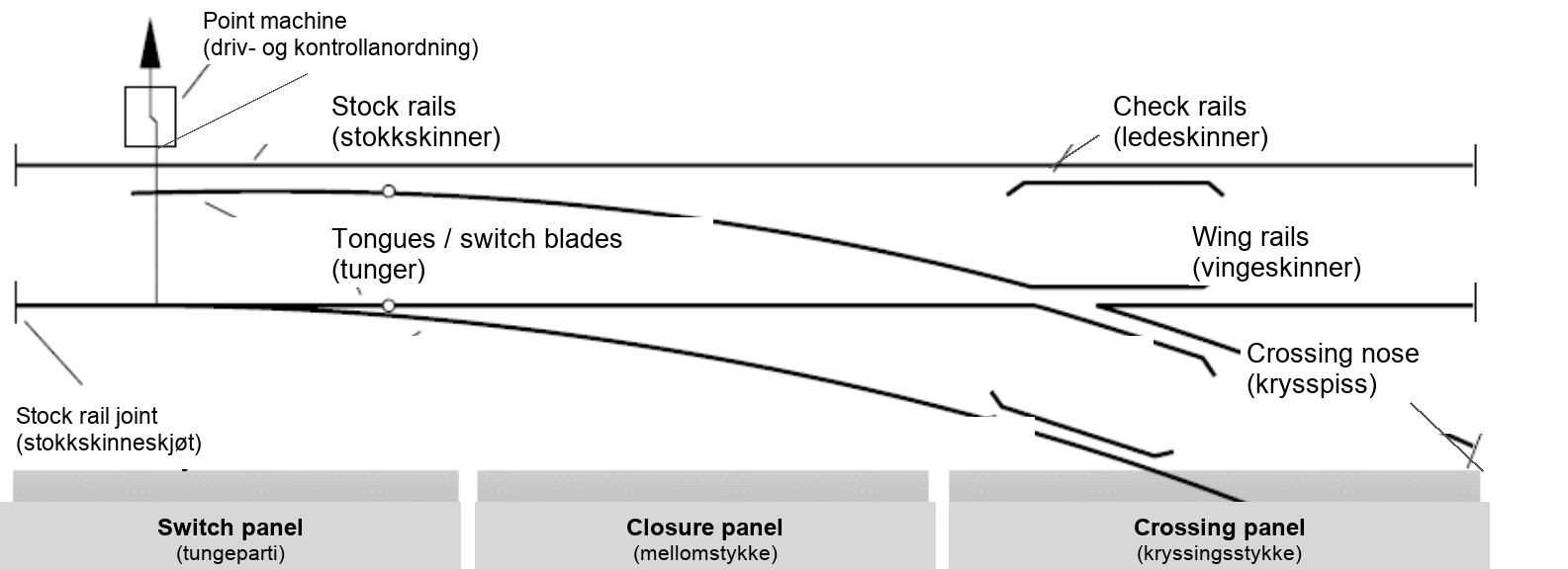
Switches and crossings are critical for operational flexibility: they enable trains to enter and leave sidings, to overtake each other in crossing loops, and to reach platform tracks in stations. Their mechanical complexity introduces failure modes not found in plain line, including switch blade failures, tongue defects, and crossing nose breakage, and their geometry creates wheel-rail contact conditions that accelerate wear and rolling contact fatigue [108, 113].
14.2 Turnout Anatomy
A simple turnout can be read as the three functional panels introduced in Figure 14.1, with each panel carrying a different part of the wheel-guidance task:
-
Switch panel (tungeparti): Contains the stock rails and the moveable switch blades or tongues (tunger). The switch panel determines whether a train is routed to the straight track or the diverging track.
-
Closure panel (mellomstykke): The transition between the switch panel and the crossing panel. Contains closure rails that guide the wheel from the switch blade to the crossing.
-
Crossing panel (kryssingsstykke): Contains the crossing or frog/heart piece (hjertestykke), wing rails, and check rails. The crossing allows one rail to cross the other.
14.3 Switch Panel: Tongue Types
The switch blade, or tongue (tunge), is the moveable rail element that guides the wheel to either track. Tongues are characterised by their flexibility and the method by which they pivot:
14.3.1 Rigid Point Switches
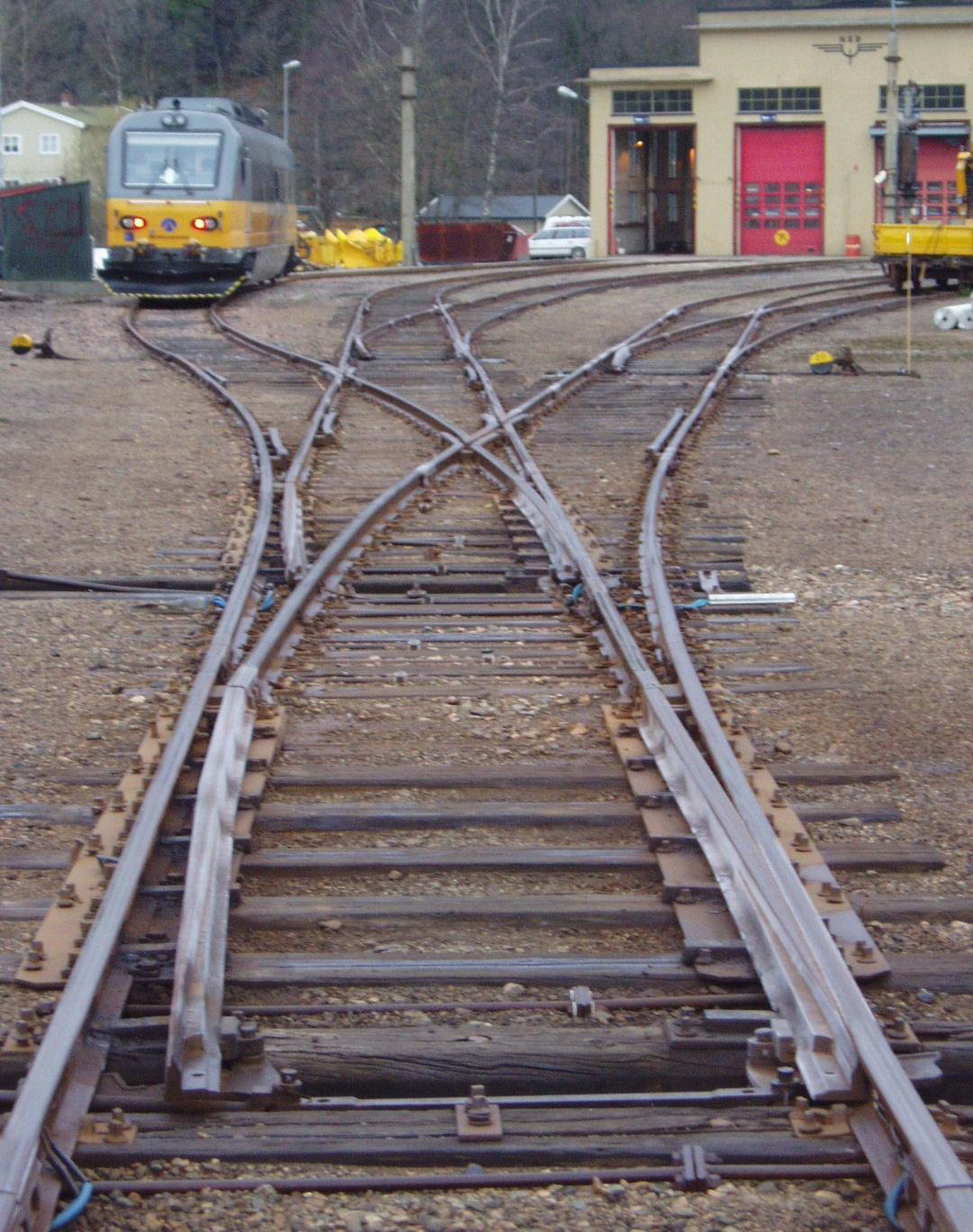
In rigid point switches (leddtunge), the tongue is a separate, rigid rail element that pivots at a hinged joint at its heel. The switch blade is not part of the continuous rail; instead, it is a separate piece connected to the stock rail by a pivot. Rigid tongues are the simplest design and were historically common, but are no longer used in new construction because the discontinuity at the heel creates a weak point and limits the achievable tongue length. The hinged arrangement in Figure 14.2 illustrates why this design is less favourable for long, high-speed tongues.
14.3.2 Flexible Switches
Flexible switches (fjærtunger) are the modern standard. The tongue is a continuous rail that is bent elastically to achieve its lateral movement. There is no mechanical hinge: the rail itself provides the flexibility through its elastic bending stiffness. Flexible tongues can be much longer than rigid tongues, which reduces the angle at the tip and allows higher speeds through the diverging route.
Two sub-types of flexible switch are used:
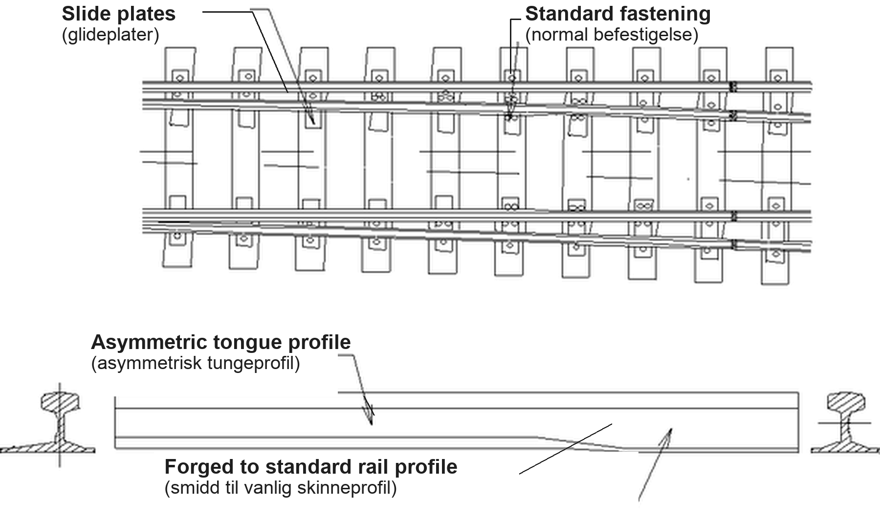
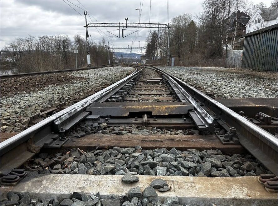
Welded flexible switches (fjærskinnetunge): The tongue is welded to the closure rail at its heel, creating a fully continuous rail without any mechanical joint. This eliminates the impact loading at the rail end and reduces maintenance requirements significantly.
In Figure 14.3, the tongue rail is continuous at the heel and tapers toward the tip; this tapering is what allows the rail to deflect elastically instead of rotating about a hinge.
The field view in Figure 14.4 shows the same arrangement in track: the tongue lies against the machined stock rail, with no mechanical joint at the heel.
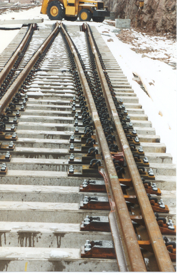
The tip of the tongue is machined to a sharp point (the toe) so that it can lie closely against the stock rail when in the closed position. Wheel loads at the tip are transmitted to the stock rail; as the wheel progresses toward the heel, the load is progressively transferred to the tongue.
14.3.3 Slide Baseplates and Support
The tongue rests on slide baseplates (glideplater) that allow it to slide laterally with low friction when the switch is operated. The baseplates must:
-
Provide a stable, smooth bearing surface for the tongue movement
-
Transmit the vertical load from the tongue to the sleeper
-
Resist wear from the repeated sliding motion
The slide baseplates, bearing details and drive hardware in Figure 14.5 carry the tongue while letting it move: the plates provide the smooth bearing surface, and the rodding connects the tongue to the point machine.
(a) Switch-blade support area
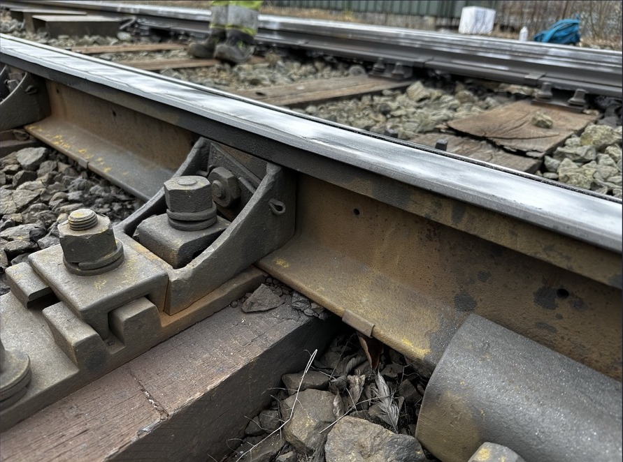
(b) Turnout support / slide-chair detail
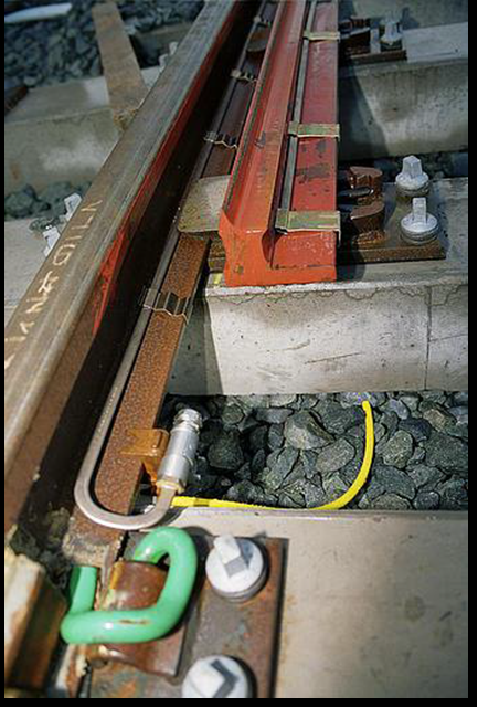
(c) Drive hardware
14.4 Point Operating Apparatus
The point operating apparatus (driv- og kontrollanordning) moves the switch blades between their two end positions (normal and reverse) and locks them in position. On all main-line turnouts, it also detects and verifies the blade position, reporting this information to the signalling system as a prerequisite for signal clearance. Modern enclosed point machines combine the actuator, transmission, locking and position-detection interfaces in a compact unit; Bane NOR's ERTMS asset catalogue lists ELS710 point machines, and current switch-and-crossing specifications reference Siemens ITS 710 interfaces for switch blades and swing-nose crossings [52, 50]. Figure 14.6 shows the installation principle: the enclosed actuator is mounted beside the switch and drives the blades through external rods.
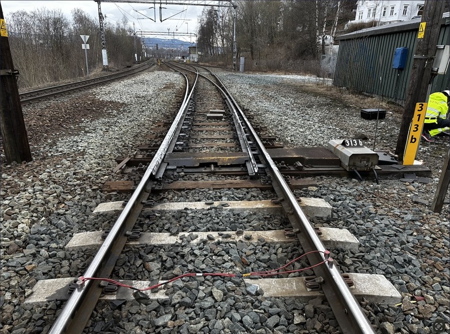
Key requirements for point machines:
-
The stroke (tongue displacement between normal and reverse positions) is typically 125–160 mm for main-line switches.
-
Locking force must prevent the blade from moving under traffic loads or in the event of a vehicle running through a mis-set switch.
-
Detection is achieved by position sensors at both the drive point and the detection rod; both must confirm correct position before the signal can be cleared.
-
Switch heaters (tungeoppvarming) protect the tongue–stock-rail area against snow and ice so the tongue can close and be detected correctly.
14.5 Crossing Panel
The crossing panel is where wheel guidance is most demanding, because the running surface is interrupted and the wheel must be steered safely across the crossing gap.
14.5.1 Crossing Geometry
The crossing (frog, hjertestykke) is the point where the two rail lines intersect. Geometrically, the crossing angle \(\alpha\) is the included angle between the two route tangents at the theoretical crossing point. The crossing geometry in Figure 14.7 identifies this point as the theoretical crossing (TK, teoretisk kryss). The crossing number \(N\) is the corresponding length-to-opening ratio:
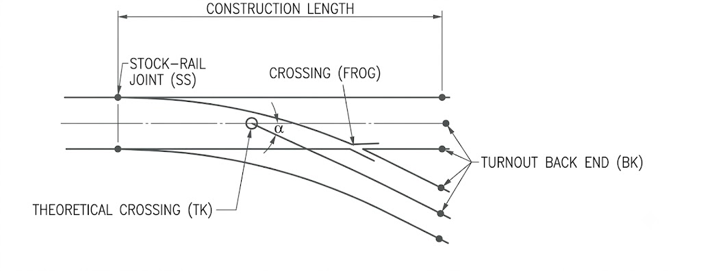
Common Norwegian crossing numbers include \(N = 7\), 9, 12, 14, 15, 18.4, and 26.1 [77, 46]. A higher crossing number indicates a smaller, flatter crossing angle and thus a higher diverging speed. For example:
-
N = 7, \(\alpha \approx 8.1^\circ\): standard station turnout, \(v_{\mathrm{div}} \leq 40\) km/h
-
N = 12, \(\alpha \approx 4.8^\circ\): main-line turnout, \(v_{\mathrm{div}} \leq 60\)–80 km/h
-
N = 18.4, \(\alpha \approx 3.1^\circ\): high-speed turnout, \(v_{\mathrm{div}} \leq 100\) km/h
-
N = 26.1, \(\alpha \approx 2.2^\circ\): high-speed turnout, \(v_{\mathrm{div}} \leq 140\) km/h
14.5.2 The Unsupported Section
The most structurally critical feature of the crossing is the gap (åpning) at the nose of the crossing. This gap is required to accommodate the flange of a wheel travelling on the intersecting rail. During wheel passage, the wheel must transfer from the wing rail to the crossing nose without a rigid bearing surface beneath it for a short distance; the visible gap in Figure 14.8 is this unsupported section.
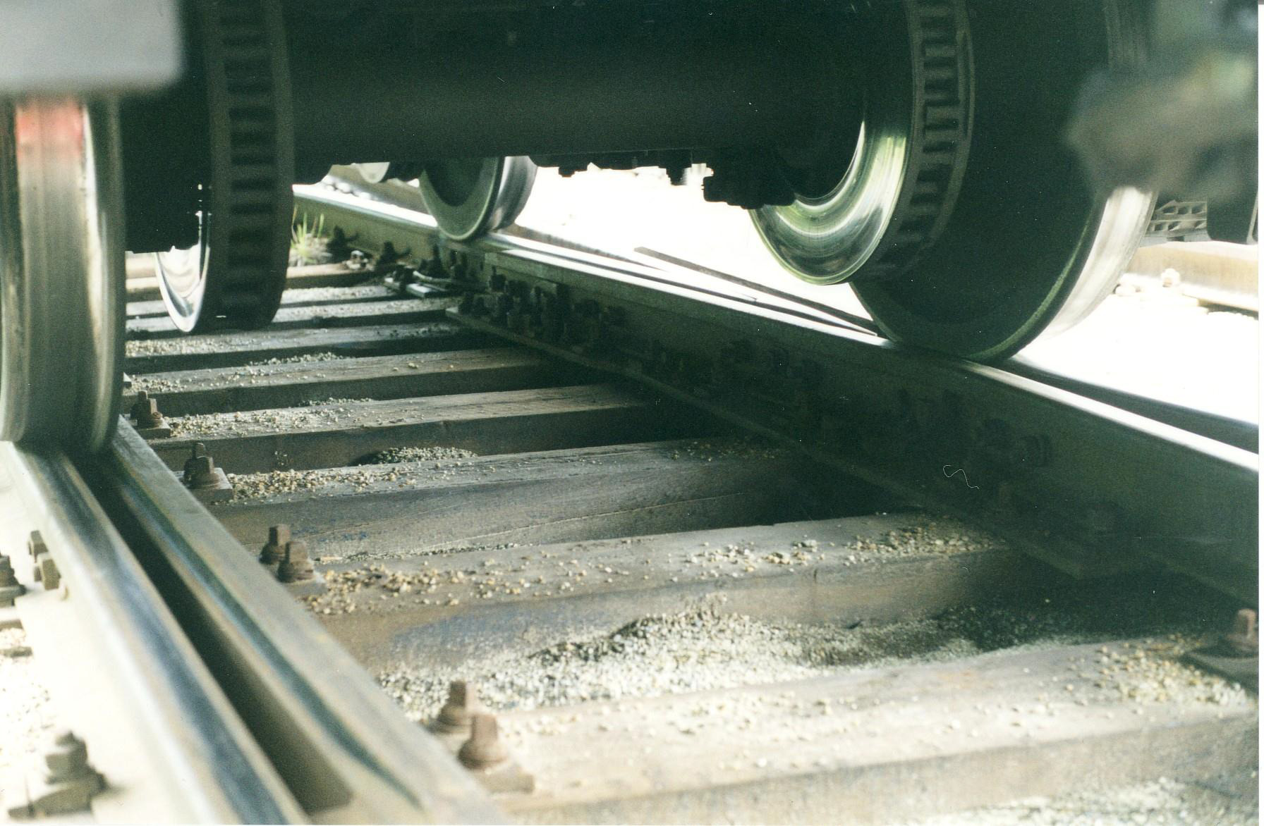
The impact at the crossing nose is the primary cause of high dynamic forces in S&C zones. These impact forces can be 2–5 times the static wheel load, leading to rapid material damage at the crossing nose (head checking, spalling, plastic deformation) [141].
14.5.3 Crossing Types
Fixed crossings are built either as machined rail assemblies or as one-piece castings. The schematic and field photo in Figure 14.9 show the same idea at two levels: the running-edge geometry and the cast crossing installed in track.
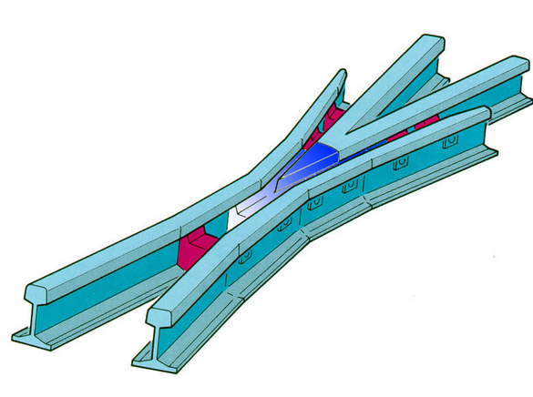
(a) Fixed crossing geometry.
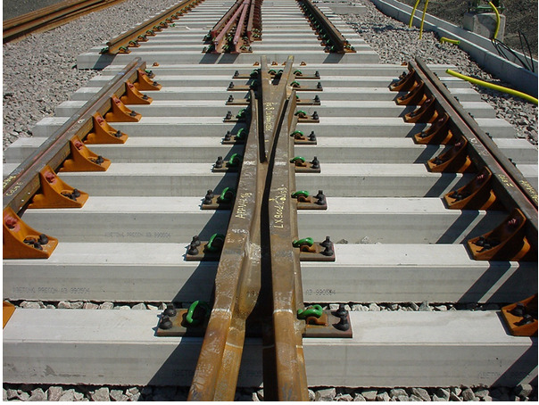
(b) Cast manganese crossing installed in track.
Two main crossing types are used on the Norwegian network:
Forged (smidd) crossings: Machined from a single piece of high-strength steel. Precise geometry, good initial profile, but limited work-hardening capacity.
Cast manganese (støpt) crossings: Made from austenitic 13% manganese steel (Hadfield steel), which is initially soft but work-hardens significantly under impact loading. Cast manganese crossings are the standard for high-traffic lines because the work-hardened surface develops high resistance to wear and impact damage [103].
14.5.4 Moveable Crossing
A moveable crossing (bevegelig skinnekryss) eliminates the unsupported section by incorporating either a moveable crossing nose (bevegelig krysspiss) or a moveable wing rail (bevegelig vingeskinne) that is set for the selected route. This closes the running edge gap for the route being used, eliminating the wheel impact at the crossing nose and significantly reducing dynamic forces and crossing nose wear. The moveable-nose arrangement in Figure 14.10 is one common way to provide this continuous running edge.
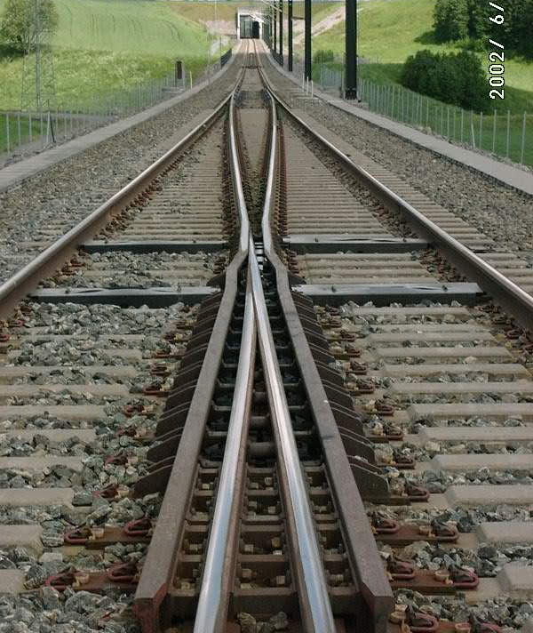
Moveable crossings require additional point machines for the nose movement and detection, but the improvement in dynamic performance and reduction in maintenance can offset the additional complexity. Under current Bane NOR technical regulations, turnouts with a base radius of 1200 m or larger shall have a moveable crossing, and moveable crossings shall also be used for turnout speeds above 250 km/h. They are recommended for noise-sensitive areas, axle loads above 22.5 t, high traffic loading above 10 MGT/year, and turnout speeds above 130 km/h [46].
14.5.5 Wing Rails and Check Rails
Because the running edge is interrupted at the nose, the wheelset must be positively guided through the crossing. The check rail visible in Figure 14.11 controls the back of the opposite wheel flange. In the complete crossing panel, it works together with the wing rails near the nose to guide the wheelset safely through the gap.
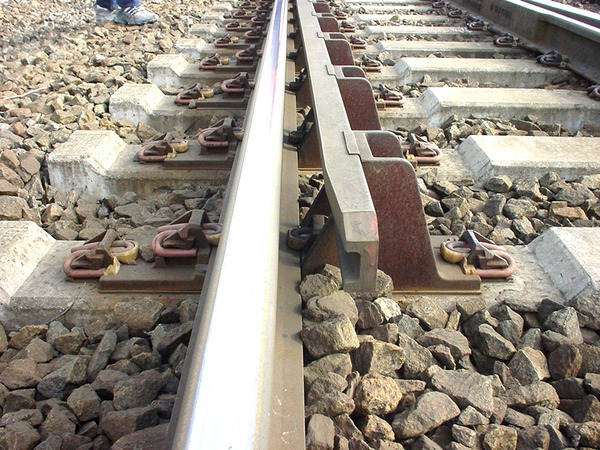
The complete crossing-panel layout in Figure 14.12 places these components together: wing rails leading up to the crossing nose and a check rail on the opposite rail.
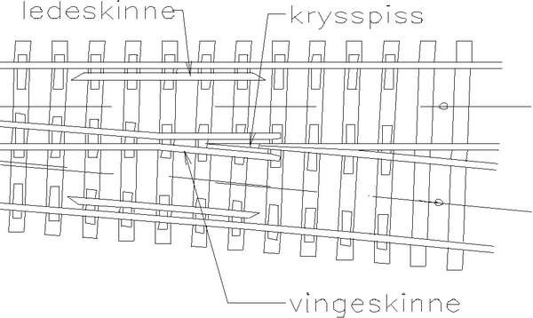
Wing rails (vingeskinner) guide the wheel from the stock rail to the nose of the crossing. They are bent outward from the crossing nose to form a smooth path.
Check rails (ledeskinner) are short rail sections installed on the opposite rail from the crossing. They constrain the lateral position of the wheel flange, ensuring the wheel tread passes over the nose of the crossing rather than into the gap. The clearance between the check rail and the back of the wheel flange must be carefully maintained.
14.6 Switch Geometry
Switch geometry connects the moveable tongue rail, closure rails, and crossing into one continuous route. The key dimensions determine both the permissible speed and the space needed in a station layout.
14.6.1 Basic Geometry Parameters
The geometry of a simple turnout is determined by reference points and lengths such as the stock-rail joint, theoretical intersection, end of curve, back end of switch, construction length, tangent-length components, turnout radius and crossing angle. Figure 14.13 shows the standard notation for the main dimensions before the speed relation is introduced.
![Main dimensions for a simple turnout (enkel sporveksel): stock rail joint (stokkskinneskjøt, SS), theoretical intersection (teoretisk kryss, TK), end of curve (R2), back end of switch (bakkant sporveksel, BK), construction length (byggelengde, L), and dimensions A–F [46].](../../assets/chapters/ch14/original/figures_source_crops/fig_switch_geometry_diagram_crop.png)
Turnout radius \(R_w\): The radius of curvature of the branching track through the switch zone. The diverging speed limit through the turnout is primarily determined by this radius and the applied cant (superelevation).
Crossing number \(N\): Defines the crossing angle as described above.
Lead length \(L_w\): The distance from the toe of the tongue to the theoretical point of the crossing nose. Longer leads allow larger turnout radii for a given crossing number.
14.6.2 Diverging Speed Limit
The maximum permitted speed through the diverging route of a turnout is a function of the turnout radius, the cant applied (typically zero on standard turnouts), and the permissible cant deficiency. For standard Norwegian turnouts:
where \(v_{\mathrm{div,max}}\) is in km/h, \(R_w\) is in metres, and \(h_a\), \(I_{\max}\), and \(S\) are entered in the same length unit. The effective rolling-contact spacing is normally taken as \(S = 1500\) mm; \(h_a\) is the applied superelevation, typically 0 for standard turnouts; and \(I_{\max}\) is the maximum permitted cant deficiency [46].
For the shorter turnout types, the permitted speeds in the technical regulations are lower than this cant-deficiency formula alone would suggest. The abrupt change of curvature at the switch toe (entry jerk) and the tongue geometry also limit the permissible diverging speed, so the tabulated values in Table 14.1 include these effects.
| Turnout type | Div. speed [km/h] | Comment |
|---|---|---|
| 1:7 R190 | 35 | Up to 40 km/h only in yards or tracks without passenger traffic |
| 1:9 R190 | 35 | Short turnout |
| 1:9 R300 | 40 | 50 km/h only after local technical and operational assessment |
| 1:12 R500 | 60 | Standard station/main-line turnout |
| 1:14 R760 | 80 | Higher-speed diverging route |
| 1:15 R760 | 80 | Alternative geometry with same basic radius |
| 1:18.4 R1200 | 100 | Clothoid turnout with moveable crossing |
| 1:26.1 R2500 | 140 | Clothoid turnout with moveable crossing |
14.6.3 Clothoid Switches
Standard turnout geometry uses a circular arc for the diverging track. A clothoid switch (klotoideveksel) introduces a spiral (clothoid) transition at the tongue tip, giving a smooth change of curvature from zero to the circular arc radius. This reduces the lateral jerk experienced by passengers and the lateral force on the track, allowing higher diverging speeds for a given turnout radius [155]. The underlying transition-curve principle is covered in Chapter 5; here the important turnout point is that the geometry spreads the curvature change over a finite length.
14.6.4 Diamond Crossings
A diamond crossing (kryss, sporkryss) allows two tracks to cross at grade without either track being directionally connected to the other. It consists of wing rails and crossing noses for both intersecting routes. A diamond crossing is not the same as a double-slip switch (dobbel kryssveksel, DKV), which adds switch blades so trains can move between the intersecting tracks. The example in Figure 14.19 later in this chapter shows why a double-slip switch is a more complex component than a plain diamond crossing.
14.7 Turnout Design in Station Layouts
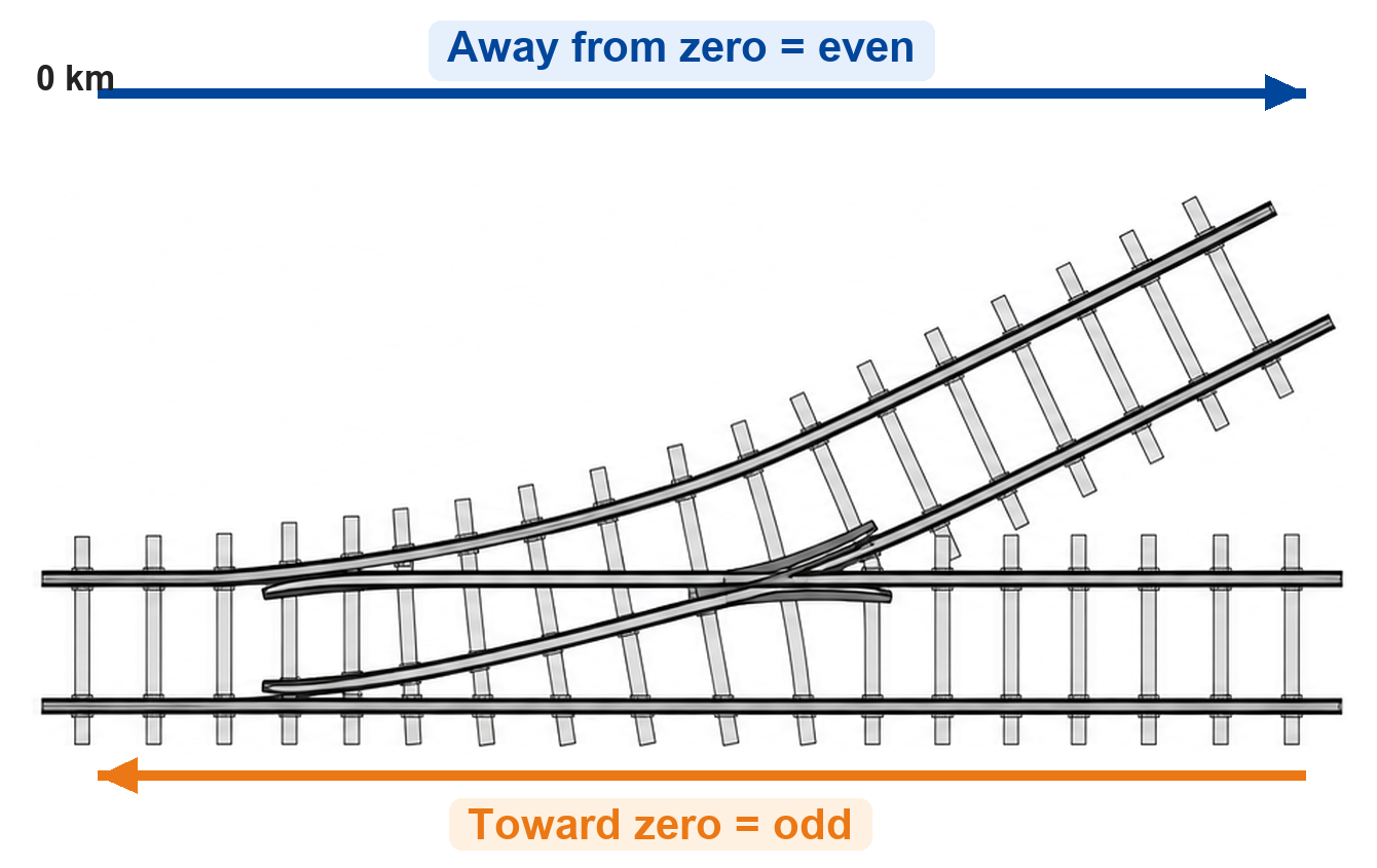
The arrangement of turnouts in a station or yard is described by a schematic plan (sporplan), which shows the track topology without regard to the actual geometric configuration, and a geographical plan (geografisk sporplan), which shows the actual geometry [65]. In Norwegian practice, switch numbering is tied to the direction toward the line's kilometre zero point, as illustrated in Figure 14.14.
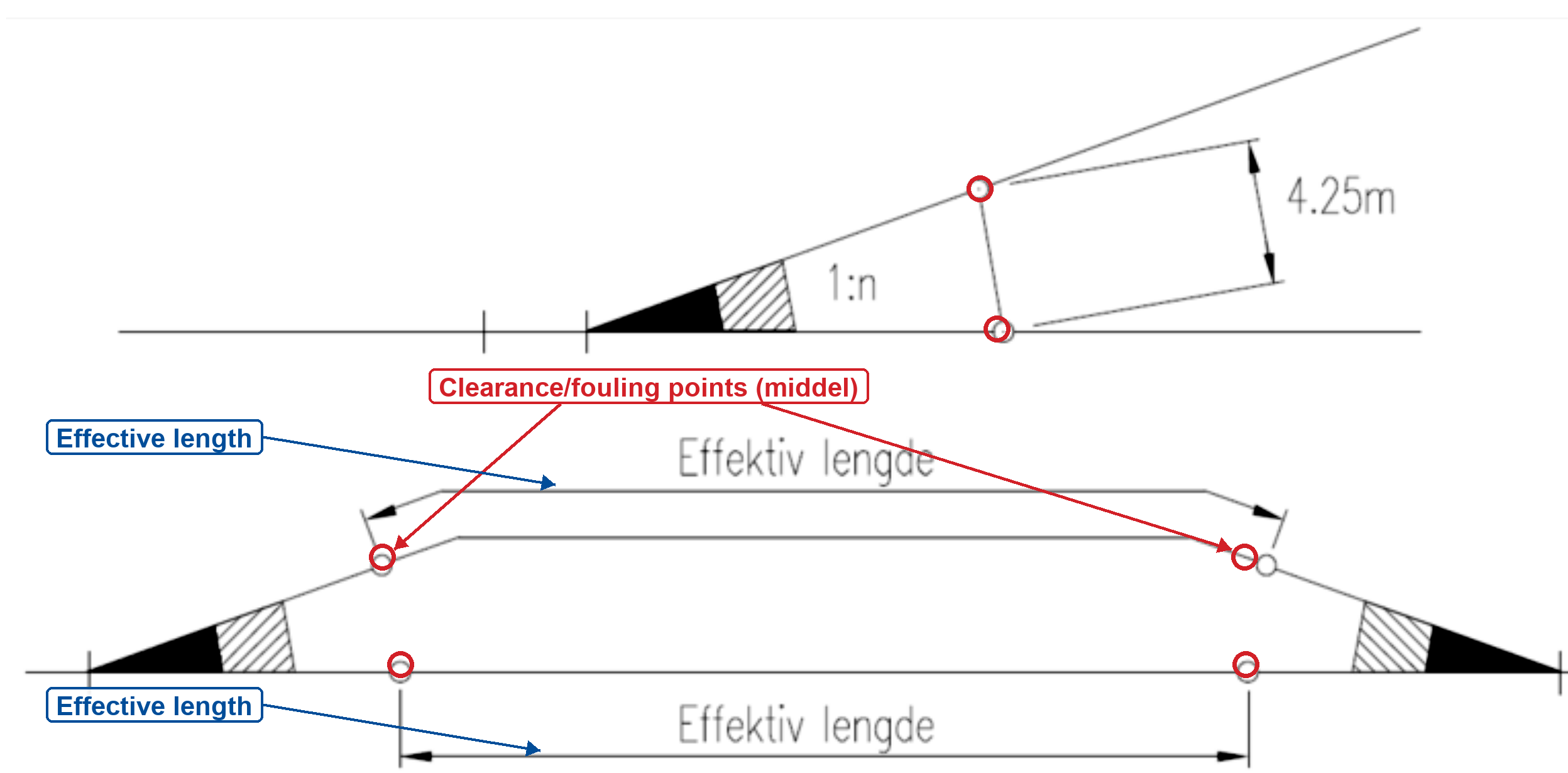
Track planning in complex stations requires careful attention to turnout geometry constraints, track separation distances (minimum clearances for adjacent platforms and tracks), gradient limitations through switch panels (turnouts are preferably placed on level or gently graded track, within the limits of the technical regulations), and the minimum track circuit lengths required for signalling. The effective length of a crossing track is governed by the clearance or fouling points (middel), not only by the physical rail length. As shown in Figure 14.15, these points define where vehicles can stand on one track without obstructing the adjacent route.
14.7.1 Curved Turnouts
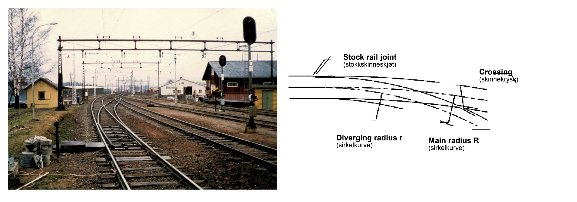
A curved turnout (kurveveksel) is a simple turnout with a long curve that has been bent so both the main route and the diverging route lie in a horizontal curve, as illustrated in Figure 14.16. Curved turnouts can solve difficult station-layout problems, but they are custom components, are harder to tamp and maintain, and are not suitable for every turnout type. In current Bane NOR rules, clothoid turnouts and turnouts with moveable crossings are not curved [46].
For preliminary layout calculations, a turnout with nominal diverging radius \(r_0\) placed in a line curve of radius \(R_\mathrm{line}\) can be estimated by adding or subtracting curvature. Same-hand cases (L/L or R/R) add curvature, while opposite-hand cases (L/R or R/L) subtract curvature:
The inside-curved case gives a smaller diverging radius than the catalogue turnout, so it can reduce the permissible diverging speed even if the longer turnout increases the available crossing-track length.
Worked example.
Consider a 1:12 R500 turnout, so the nominal diverging radius is \(r_0 = 500\) m. If it is curved into a same-hand line curve with \(R_\mathrm{line}=1000\) m, the effective diverging radius becomes
For an opposite-hand curved turnout in the same line curve,
Using Eq. 14.2 as a screening calculation with \(h_a=0\), \(I_{\max}=100\) mm \(=0.100\) m, \(S=1500\) mm \(=1.500\) m and \(g=9.81\,\mathrm{m/s^2}\), the nominal R500 geometry gives
whereas the same-hand curved case gives
The same catalogue turnout can therefore behave like a much tighter turnout when it is curved in the same direction as the main-line curve. The final permitted speed must still be taken from the technical regulations and local approval process, but the calculation shows why the radius effect has to be checked.
14.7.2 Worked Example: Drammen/Nybyen Layout Review
The 2025 Drammen/Nybyen temporary-stabling study is a useful design-review example because the schematic plan appears simple while the geographical plan exposes severe space and geometry constraints. Figure 14.17 shows the two plan views that must be read together.
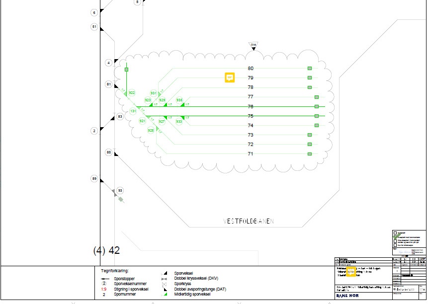 (a) Schematic plan: topology and intended stabling tracks.
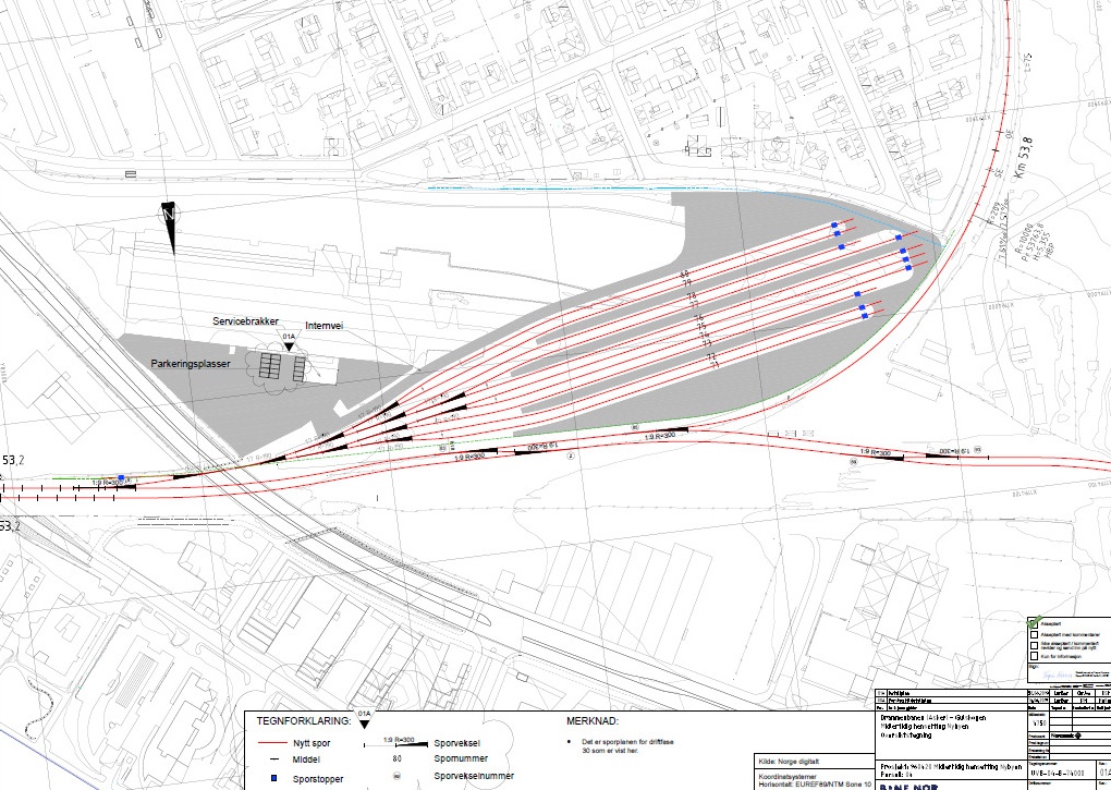 (b) Geographical plan: the same functions fitted to the real site.
Design question. A double crossover is needed before the stabling area. Two concepts are screened: four curved turnouts outside the station, or a scissors crossover on the tangent section. The objective is not to choose the visually smallest layout; it is to find an arrangement that satisfies turnout geometry, effective platform length, maintainability, signalling, and constructability together.
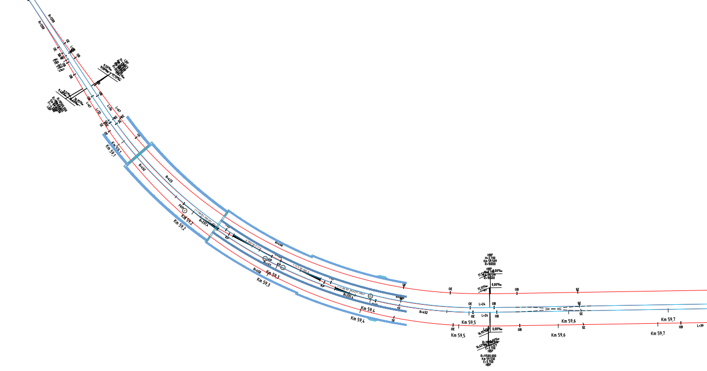 (a) Four curved turnouts outside the station.
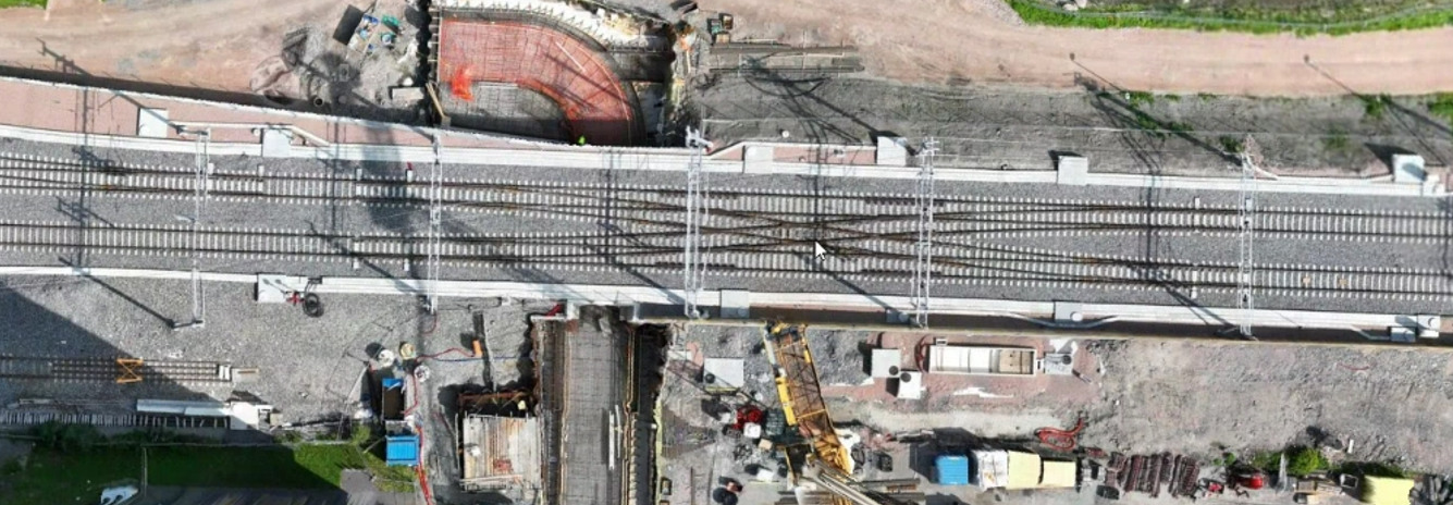 (b) Scissors crossover on the tangent section.
Step 1: screen the curved-turnout concept. The four-turnout arrangement preserves the required crossover function, but the available line curvature makes the resulting curved turnouts sharper than permitted by the applicable technical requirements. It also creates custom components with higher inspection, tamping, and renewal demand. The concept therefore fails the preliminary geometry and maintainability screen.
Step 2: screen the scissors-crossover concept. Moving the connection to tangent track improves the basic turnout geometry, but a scissors crossover combines four turnouts and a diamond crossing in a compact and maintenance-intensive panel. More importantly, the fouling points reduce the effective platform length below the operational requirement. This concept therefore fails the effective-length screen even before detailed signalling and constructability checks.
| Criterion | Four curved turnouts | Scissors crossover |
|---|---|---|
| Required connectivity | Satisfied | Satisfied |
| Turnout geometry | Fails: curves are too sharp | Improved on tangent track |
| Effective platform length | Potentially retained | Fails: fouling points shorten the usable track |
| Maintainability | Poorer: custom curved panels | Poorer: dense four-turnout/crossing panel |
| Preliminary outcome | Reject or redesign | Reject or redesign |
- Preliminary feasibility screen for the Drammen/Nybyen alternatives.
Engineering conclusion. Neither concept is ready for approval. The professional response is to iterate the site layout, operational requirements, or connection location, and to document any proposed deviation explicitly; it is not to select a non-compliant "least bad" option without a quantified risk and maintenance assessment. A station-layout decision must apply the same distinction between topology and real geometry and be justified against clearance, effective length, and maintainability.
14.8 Slip Switches
A slip switch (kryssveksel) combines a diamond crossing with one or two turnout movements, allowing trains to cross from one track to the other within the diamond. Slip switches are used in space-constrained locations where separate simple turnouts cannot be accommodated.
Single-slip switch (enkel kryssveksel, EKV): One set of switch tongues is added to one of the four crossing angles of a diamond, allowing trains to branch from one track to the other in one direction only. A train approaching from the other direction passes straight through the diamond without switching.
Double-slip switch (dobbel kryssveksel, DKV; DSS): Switch tongues are added at two opposing angles of the diamond, allowing trains to branch from either approach direction. A double-slip switch is kinematically equivalent to two turnouts in opposite directions placed back-to-back, but within the footprint of a single diamond crossing.
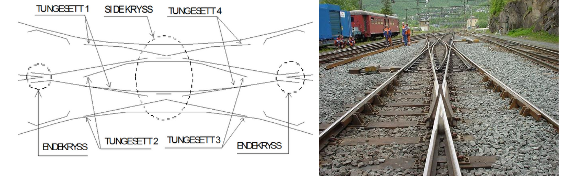
Slip switches are particularly common in large city stations (for example Oslo S), where multiple platform roads must connect through tight spaces [141, 124]. Their disadvantage is high maintenance intensity: a double-slip switch has four separate tongue sets and four crossing noses in a single structure, all requiring separate inspection, lubrication, and point-machine maintenance.
14.9 Dynamic Forces in Switches and Crossings
Switches and crossings are subjected to higher dynamic forces than plain track, for two reasons:
-
Geometric discontinuities: The wheel must transfer from one running surface to another (at the tongue tip and at the crossing nose) across a gap or step. The resulting impact produces a dynamic force that can be 2–5 times the static wheel load.
-
Reduced support: The crossing nose zone and the region near the tongue tip have reduced or discontinuous ballast/sleeper support, increasing bending stresses in the rail and contact stresses at the wheel.
14.9.1 Impact at the Crossing Nose
As a wheel approaches the crossing nose from the wing rail side, it rolls over the wing rail and crosses the unsupported section before landing on the crossing nose or the other wing rail. The vertical velocity of the wheel during this transition is:
where \(v_x\) is the train speed, \(\Delta h\) is the height difference at the crossing nose tip, and \(L_\text{gap}\) is the effective gap length. The resulting impact force is [65]:
where \(m_u\) is the unsprung mass per wheelset (typically 1200–1500 kg) and \(\Delta t\) is the duration of the impact (\(\approx 1\)–3 ms). This impulse estimate is only indicative: the actual peak contact force depends on wheel and rail stiffness, support condition, damping, speed, and crossing geometry. Peak forces can reach 200–400 kN for a wheel load of 80 kN, explaining the rapid wear and deformation of crossing noses.
Moveable crossings eliminate the unsupported gap: the crossing nose or wing rail moves to close the running edge before the train arrives, providing continuous support across the geometry transition. This dramatically reduces impact forces and crossing nose wear. In Norwegian design practice, the strongest requirements and recommendations are linked to large-radius turnouts, high speed, high axle load, high annual tonnage, and noise-sensitive locations [46].
14.9.2 Dynamic Amplification Factor at S&C
The dynamic amplification factor \(\Phi_{\text{S\&C}}\) for S&C zones is typically expressed as a factor on the static wheel load:
For a fixed crossing nose, \(\Phi_{\text{S\&C}} \approx 2\)–5 depending on train speed and crossing geometry. For a moveable nose in correctly adjusted condition, \(\Phi_{\text{S\&C}} \approx 1.2\)–1.5, because the wheel transition is smoother and impact forces are lower.
| Element / Condition | \(\Phi_{\text{S\&C}}\) | Comment |
|---|---|---|
| Fixed crossing nose (new, correct profile) | 2.0–3.0 | Standard condition |
| Fixed crossing nose (worn, dipped) | 3.0–5.0 | Increased settlement |
| Moveable nose (new, well adjusted) | 1.2–1.5 | Near plain-line level |
| Tongue tip transition | 1.5–2.5 | Speed-dependent |
| Plain track reference | 1.0–1.3 | Eisenmann formula |
Worked example.
Consider a wheel with static load \(Q_\mathrm{static}=80\) kN passing a fixed crossing at 80 km/h, so \(v_x=22.2\) m/s. Assume a representative unsupported crossing gap of \(L_\text{gap}=0.18\) m, a vertical landing difference of \(\Delta h=2.5\) mm, an unsprung mass per wheelset of \(m_u=1300\) kg, and an impact duration of \(\Delta t=2\) ms. From Eqs. 14.5 and 14.6,
The estimated peak wheel–rail force is therefore roughly \(80+200=280\) kN.
For a moveable crossing, the same running-edge opening is closed before the train arrives. The wheel no longer has to bridge an unsupported gap, so the gap-impact part of the calculation is removed:
In the ideal gap comparison, the moveable crossing therefore removes about 200 kN of impact surcharge. A real crossing may still have a small residual profile irregularity. For a conservative screening allowance, assume \(\Delta h_\mathrm{res}=1.0\) mm over a characteristic transition length \(L_\mathrm{trans}=0.18\) m; this is not an unsupported gap, but a residual geometry tolerance after the running edge has been closed:
With this residual allowance, the moveable-crossing peak force is about \(80+80=160\) kN instead of 280 kN. The important point is that the unsupported gap contribution itself has been eliminated; the remaining surcharge represents profile and support imperfections that must be controlled by adjustment and maintenance.
The high dynamic forces in S&C zones drive the accelerated wear and fatigue damage compared with plain track. Infrastructure managers use dynamic force measurements (from instrumented wheelsets or strain-gauged S&C panels) to assess the condition of crossing noses and trigger maintenance or replacement.
14.10 Maintenance of Switches and Crossings
Switches and crossings require intensive maintenance because of their geometric complexity, the dynamic forces at the crossing nose, and the wear of moving parts. The key maintenance activities are:
Tongue inspection and lubrication: The tongue–stock rail contact zone and the slide baseplates are inspected for wear and lubricated at regular intervals. The required contact between the closed tongue and the stock rail must be verified against the applicable maintenance tolerance [160].
Crossing nose inspection: The crossing nose and wing rails are inspected for plastic deformation, head checking, and spalling. Cast manganese noses are evaluated by measuring the nose width at defined cross-sections; corrective grinding is applied when surface defects develop.
Crossing nose grinding: Unlike plain rail, cast manganese crossings often require special treatment because manganese steel work-hardens and can clog ordinary abrasive stones. Special grinding methods, milling, or profile restoration by build-up welding are used [124].
Point machine maintenance: Point machines are inspected and tested at defined intervals to verify correct stroke, locking force, and detection sensitivity. Heater function is tested before the winter season.
Geometry tamping: S&C zones are tamped with specialised tamping machines that can handle the complex geometry of the crossing panel and the non-standard sleeper spacing. Multiple passes may be required.
Figure 14.20 shows two typical examples. The crossing-nose photo is an example of surface damage, such as batter, metal flow and local cracking, that S&C inspections are intended to find before it develops into a critical defect. Switch-panel tamping is also slower than plain-line tamping because the machine must lift and pack around long bearers, rodding and the point machine without damaging them.
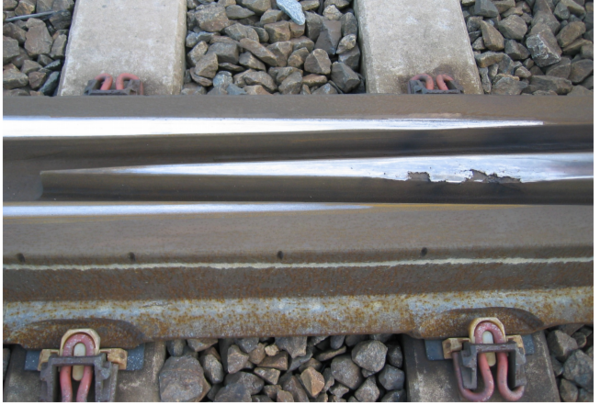
(a) Crossing-nose surface condition
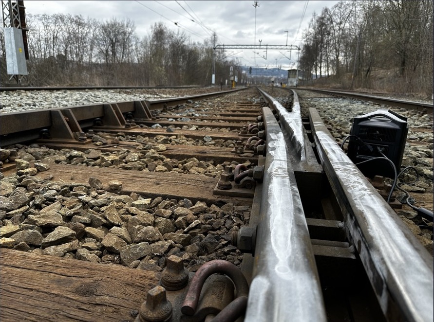
(b) Fixed crossing in field-inspection context
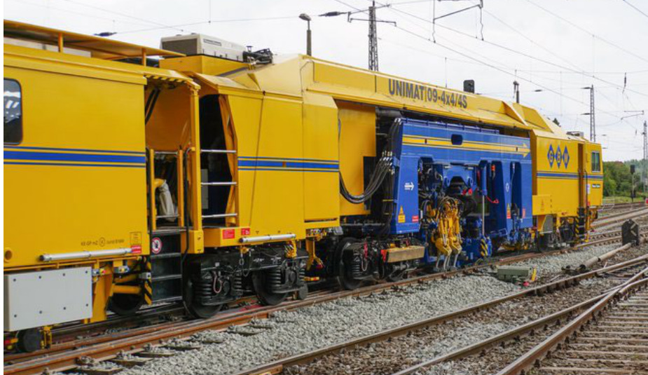
(c) Switch-panel tamping and geometry correction
14.11 Chapter Summary
Route flexibility. Switches and crossings allow trains to move between tracks, enter platforms, cross routes and create operational flexibility, but they also interrupt the simple running geometry of plain track. Wheels must pass through switch blades, closure rails, check rails, wing rails and crossing noses, often with changing support and contact conditions. This makes S&C zones among the most maintenance-intensive parts of the railway.
Switch geometry. The switch toe, lead length, crossing angle, crossing number and turnout radius define the diverging route. Sharp turnouts require less space but impose lower speed and higher lateral force, while higher-speed turnouts require gentler geometry and longer layouts. The engineer must therefore balance station throat compactness, permissible speed, capacity and constructability.
Layout compromises. Curved turnouts and slip switches can solve difficult station-throat problems when space is limited, but both increase maintenance complexity. Curving a turnout changes the effective diverging radius, and a same-hand curved turnout can reduce the diverging speed even when it improves crossing-track length. Slip switches save space by combining several movements inside one diamond, but they concentrate many tongues, noses and detection points in one asset.
Crossing nose. In a fixed crossing, the wheel transfers from wing rail to crossing nose through an unsupported gap needed for the wheel flange. This transfer produces impact loading, noise, wear and dynamic amplification. Check rails guide the wheelset so the wheel takes the correct path, while moveable point crossings reduce impact by closing the running edge gap for the selected route.
Support and operation. Slide baseplates, point machines, locking devices and detection equipment are part of the same system as the rails. The switch must move, lock and be detected reliably before a route can be authorised, and the track must still provide adequate vertical and lateral support under traffic. This links S&C design directly to signalling, maintenance access and operational reliability.
Maintenance demand. Wear, plastic deformation, cracking, poor support, ballast degradation and point-machine issues are common because contact conditions vary rapidly through the turnout. High quality inspection, tamping, lubrication, grinding and timely renewal are therefore essential. Reducing unnecessary turnouts can improve both reliability and life-cycle cost because each S&C unit adds inspection and maintenance exposure.
Assignments
Assignment 1: Turnout components and operation
Use Figures 14.1, 14.5 and 14.6 to explain how a simple turnout is built and operated.
(a) Divide the turnout into switch, closure and crossing panels, and state the main wheel-guidance function of each panel.
(b) Identify the stock rails, switch blades/tongues, slide baseplates, closure rails, crossing nose, wing rails and check rails. State one maintenance-sensitive feature for each of the three panels.
(c) Explain the difference between a rigid point switch and a flexible switch, and why flexible tongues are preferred in modern main-line turnouts.
(d) Describe the functions of the point operating apparatus: movement, locking, detection and signalling interface.
Assignment 2: Crossing number and diverging speed
A station turnout has crossing number \(N = 9\) and turnout radius \(R_w = 300\) m.
(a) Estimate the crossing angle \(\alpha\) from the crossing number and explain what a larger crossing number means for the turnout geometry.
(b) Using Eq. 14.2, no cant, \(I_{\max}=100\) mm, \(S=1500\) mm and \(g=9.81\,\mathrm{m/s^2}\), calculate the theoretical speed through the diverging route.
(c) Compare the result with Table 14.1. Explain why the regulatory value for a 1:9 R300 turnout is lower than the simple cant-deficiency calculation.
Assignment 3: Turnout renewal and crossing-track length
At a station with a single crossing track, turnout 1 must be renewed. The existing turnout has rails 49E1 and is of type 1:9 with \(R = 300\) m (SK1800). To increase the speed in the diverging track, which is currently limited to 40 km/h, it is considered to replace it with a turnout of type 54E3, 1:12 with \(R = 500\) m.
(a) Using Table 14.1, how much can the diverging speed be increased?
(b) If the new turnout is placed with the same stock-rail joint position, the crossing track becomes shorter. Assuming the clearance/fouling point is reached when the track-centre spacing is 4.25 m, estimate the distance from the stock-rail joint to the clearance/fouling point for the 1:9 and 1:12 turnouts. How much is the available crossing-track length shortened?
(c) An alternative location for the new turnout is in a same-hand line curve with \(R_\mathrm{line}=600\) m. Calculate the effective diverging radius using Eq. 14.3. Discuss whether this helps or hurts the intended speed increase.
Assignment 4: Station layout and special turnouts
Bane NOR is planning a compact through station with two main tracks and two platform tracks. Trains approaching from one end should be able to reach both platform tracks.
(a) Sketch a station-throat layout using simple turnouts. Indicate the switch numbering direction relative to line zero and mark the clearance/fouling points that govern the effective crossing-track length.
(b) Select suitable crossing numbers for the platform-entry turnouts and justify the choice using required diverging speed and available layout length.
(c) If space is too limited for the simple-turnout solution, explain when a diamond crossing, single-slip switch or double-slip switch could be considered.
(d) Explain why slip switches and diamond crossings normally increase inspection, tamping and failure-management complexity compared with simple turnouts.
Assignment 5: Crossing impact, moveable crossings and maintenance
A wheel with static load \(Q_\mathrm{static}=100\) kN passes through an S&C zone.
(a) Use Eq. 14.7 and Table 14.3 to estimate the dynamic wheel–rail force for: a fixed crossing nose in good condition (\(\Phi_{\text{S\&C}}=2.5\)), a worn or dipped fixed crossing nose (\(\Phi_{\text{S\&C}}=4.0\)), and a well-adjusted moveable nose (\(\Phi_{\text{S\&C}}=1.4\)). Calculate the surcharge above the static load in each case.
(b) A new main-line turnout has diverging speed 140 km/h, nominal radius 2500 m, axle load 23 t, annual traffic loading about 12 MGT/year, and nearby noise-sensitive buildings. Should a moveable crossing be required, recommended or optional? Justify the answer using the design guidance in the chapter.
(c) List the extra inspection and maintenance checks introduced by a moveable crossing, and explain why the added mechanical and signalling complexity can still be justified.