Structure Gauge
In this chapter
14.1 Introduction
The structure gauge defines the cross-sectional envelope that must remain clear of all fixed installations along the railway. It is one of the most fundamental interface requirements in railway engineering, governing everything from tunnel cross-sections and platform edge positions to catenary mast placement and signalling equipment. This chapter covers the definitions and Norwegian gauge profiles, curve overthrow calculations, the space required for moving vehicles, and the methods used to verify structure gauge compliance.
This introduction establishes the main gauging terms used throughout the chapter. The distinctions between vehicle profiles, dynamic reference profiles, and infrastructure clearances are important because later calculations assign responsibility to different parts of this hierarchy.
Gauging also affects transport capacity. A route may have enough train paths and axle-load capacity yet still be unable to carry a particular container, timber load or double-deck vehicle. The usable vehicle cross-section and length must be compatible with the entire route, including platforms and neighbouring tracks, not just its largest tunnel.
Structure gauge is one part of railway capacity, alongside track gauge, number of tracks, speed, axle load, train length, power supply, signalling/headway and infrastructure availability. A generous vehicle envelope increases usable passenger or freight volume only if the intended route can accommodate it. A profile is therefore a contour and its associated calculation rules, not simply a drawing to fit around a train.
14.1.1 Structure Gauge
The structure gauge is the cross-section of the space on every side of and above the track that must be free of all obstacles. The civil engineer is responsible for ensuring that no structure or piece of equipment is placed inside this boundary. The hierarchy is easiest to read from the vehicle outward to the infrastructure clearance:
- A: Vehicle (construction) profile
-
The construction outline within which the vehicle and its components must fit. Its dimensions, suspension displacements and curve geometry are inputs to the movement-envelope check; the construction outline alone is not the complete swept envelope.
- B: Reference (dynamic) profile
-
The dividing boundary between vehicle and infrastructure responsibility, e.g. the Norwegian reference profile NO1. It encloses all dynamic movements of the rolling stock.
- C: Structure gauge
-
The minimum envelope the infrastructure must keep clear; determined by the reference profile plus infrastructure safety margins.
- D: Pantograph gauge (Cross-section E)
-
The special envelope for the overhead line system on electrified lines. It has no curve overthrow adjustment.
To separate infrastructure responsibility from rolling-stock responsibility, Figure 14.1 places these four envelopes in relation to one another, from the vehicle construction profile to the infrastructure clearance and pantograph gauge.
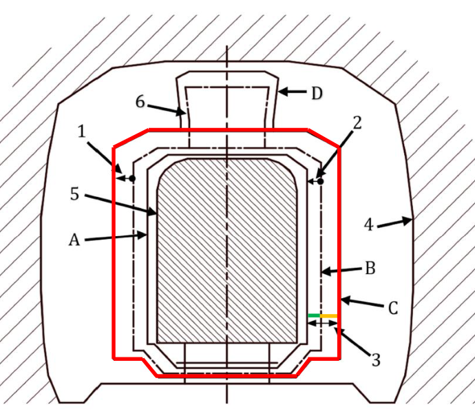
The numbered arrows in Figure 14.1 distinguish the two sides of the clearance margin: (1) the infrastructure-side enlargement outside the reference profile; (2) the vehicle-side reduction inside the reference profile; and (3) their combined clearance margin. The remaining labels identify (4) the actual infrastructure boundary, (5) the actual vehicle outline, and (6) the pantograph reference profile. Thus, arrows 1 and 2 are not interchangeable, and arrow 3 is their sum, not a separate curve allowance. On electrified lines, check the free pantograph profile and Cross-section E separately as required by Bane NOR [51, 41].
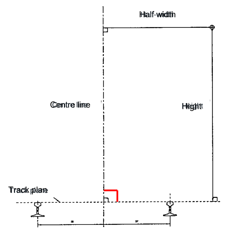
The gauging coordinate system is centred on the track centre line. Heights are measured perpendicular to the track plane through the two rail tops; this plane is inclined where the track is canted.
Figure 14.2 locates the half-width and height in this coordinate system. The height axis is normal to the track plane, not necessarily vertical in the global coordinate system.
14.1.2 Static and Dynamic Profiles
Gauge profiles are commonly separated into static and dynamic cases. The static case describes the vehicle at rest, while the dynamic case includes the additional movements that occur in service.
- Static profile
-
The minimum free space required with the vehicle stationary.
- Dynamic profile
-
The minimum free space required with the vehicle in motion, accounting for all suspension movements, wheel–rail clearances, roll, and curve overthrow. The dynamic profile is always larger than the static profile.
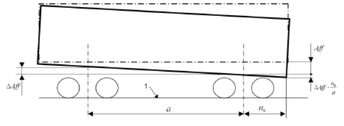
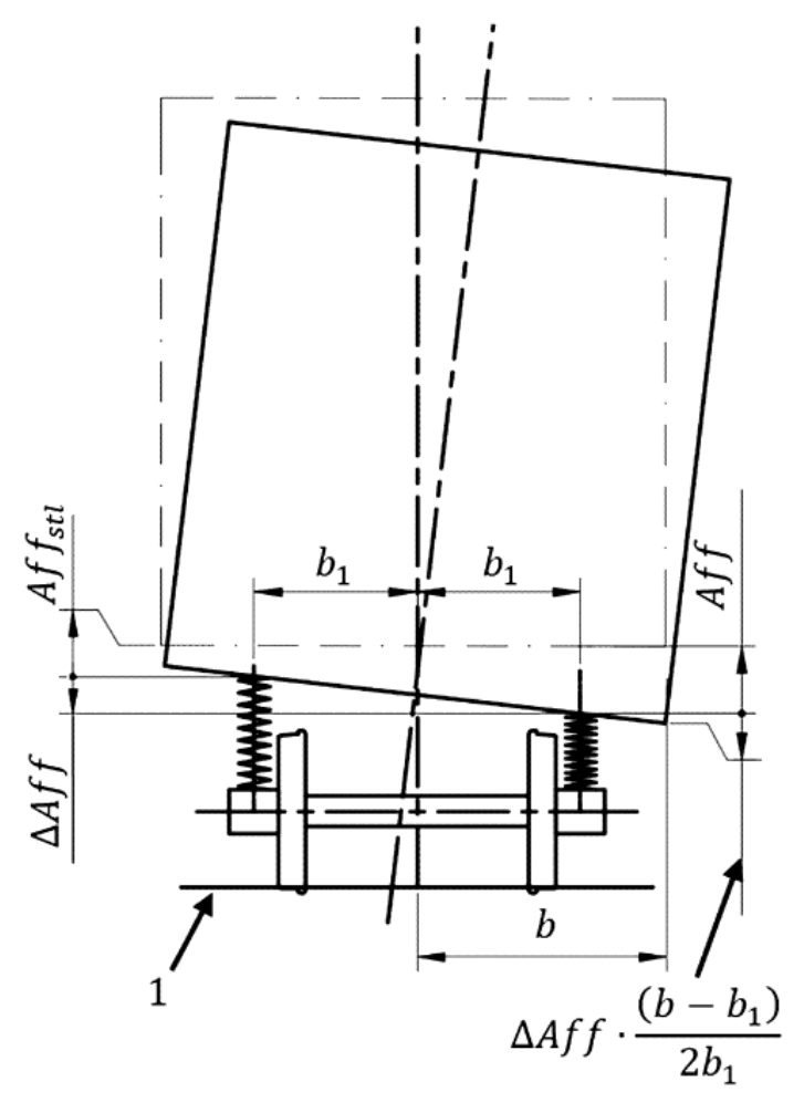
A stationary vehicle is not necessarily in its nominal unloaded shape. Static loading compresses the suspension; unequal compression can pitch the body along its length or roll it across the track. Additional displacement arises under unbalanced acceleration and from suspension tolerances. These effects explain why a static operating case can still require movement allowances. Conversely, movements already included in an approved dynamic reference profile must not be added a second time.
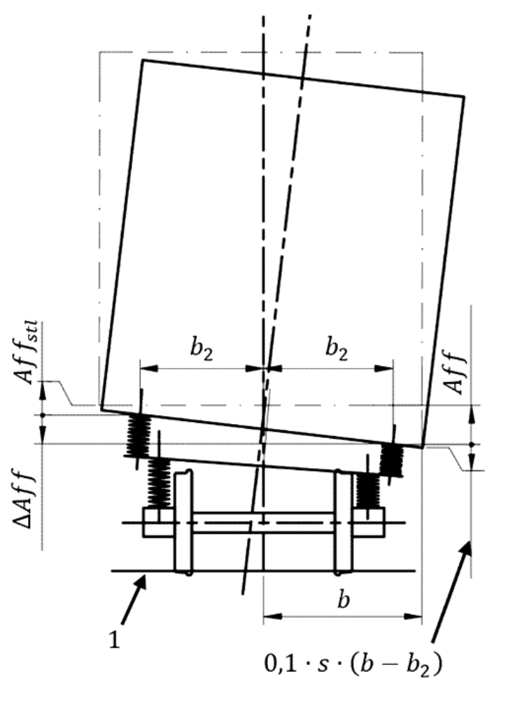
Unequal suspension compression changes more than the body height. Figure 14.3(a) shows longitudinal pitch; 14.3(b) and 14.3(c) show transverse displacement with one and two suspension stages. The body side can move beyond its nominal position even while the vehicle is stationary.
(a) Longitudinal pitch
(b) One suspension stage
(c) Two suspension stages
14.1.3 Regulations
The EN 15273:2025 series defines the calculation rules for rolling-stock and infrastructure gauging. EN 15273 Parts 1–4 cover common rules, rolling stock, infrastructure and the catalogue of defined gauges, while CEN/TR 15273-5 provides background and worked examples [94]. Bane NOR technical regulations reference EN 15273 and specify the Norwegian gauges that apply to each line.
14.2 Infrastructure Profiles
The infrastructure profiles specify the space to keep clear around the track. New-line and existing-line gauges are followed here by snow-plough clearance, Cross-section E and tunnel profiles.
14.2.1 Gauges for New Lines
New infrastructure is designed with a more generous clearance envelope than many historical lines. The dimensioned new-line profile in Figure 14.4 is the baseline structure gauge before local curve, cant and dynamic allowances are added.
Bane NOR specifies a structure gauge for new lines, which is wider and taller than the historical gauges. This gauge is compatible with the GC freight loading gauge, where GC is a large European/UIC loading gauge for intermodal freight such as ISO containers and semi-trailers. It must also be checked against the passenger rolling-stock profiles approved for the route, the pantograph/catenary envelope, platform interfaces and local restrictions [51].
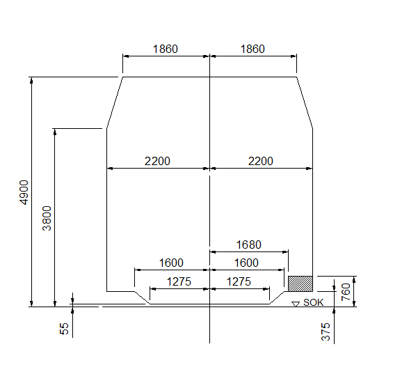
Drawing notation: SOK denotes top of rail.
The shaded lower areas indicate specific permitted encroachments for platform edges and signalling equipment in station areas. They do not allow arbitrary equipment inside the profile. The A-85 drawing uses corresponding station-area exceptions; any special-transport route through a station must be checked separately. [51]
14.2.2 Gauges for Existing Lines
For an existing route, the first question is an infrastructure question: which obstacle-free cross-section must the line provide? Existing Norwegian lines use a set of historical structure gauges; these are the clearance envelopes for fixed infrastructure, not vehicle profiles. Figure 14.5 compares the structure gauges used for train passage on existing lines.
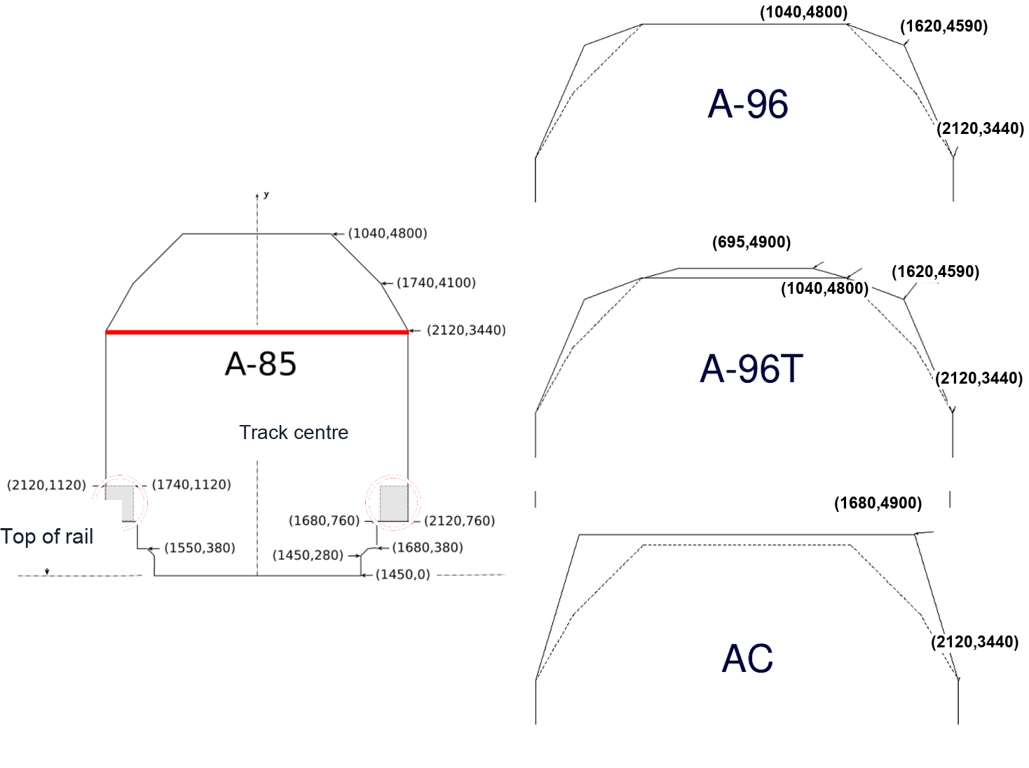
Bane NOR treats A-85 as the basic minimum cross-section for existing lines. A route may additionally be required to satisfy A-96, A-96T, AC (written A-C in the technical regulations) or a snow-plough profile, depending on the traffic the route is intended to carry [51]. The main existing-line profiles are:
- A-85
-
Basic existing-line clearance profile and the smallest of the Norwegian structure gauges.
- A-96
-
Same lower profile as A-85, but with revised upper points for combined transport such as containers and semi-trailers.
- A-96T
-
A top-profile variant of A-96, intended for foreign freight wagons and double-deck passenger vehicles.
- AC
-
Extended existing-line profile for routes that must carry UIC GC traffic.
This subsection is therefore the infrastructure side of the compatibility check. The structure gauge must still be widened or checked for curve overthrow, station-area restrictions, electrification envelopes and local intrusions before vehicles are accepted on a particular route.
14.2.3 Snow-Plough Profile
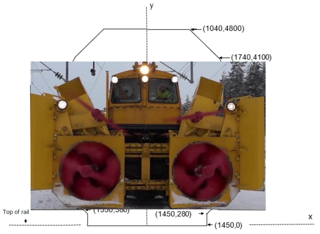
The snow-plough profile is an enlargement of A-85 for routes where snow displaced by a train-mounted plough needs additional room. It is distinct from the low-level clearance required by a track snow scraper (sporrenser).
Figure 14.6 shows the relationship between the vehicle-mounted plough and the extra space beside the normal profile. This lateral snow-clearance envelope is a different check from the scraper clearance below rail level discussed later.
14.2.4 Cross-section E
Cross-section E reserves space for the pantograph and overhead line. Its height is expressed as \(H_E=H_0+C+d_1\): contact-wire height, overhead-line construction height and the clearance above the messenger wire. Neither Cross-section E nor the free pantograph profile receives the train-body curve-overthrow addition; their own mechanical and electrical checks still apply.
In Figure 14.7, the upper space follows the overhead-line arrangement rather than the vehicle roof alone. The contact wire and messenger wire therefore need their own height and clearance checks.
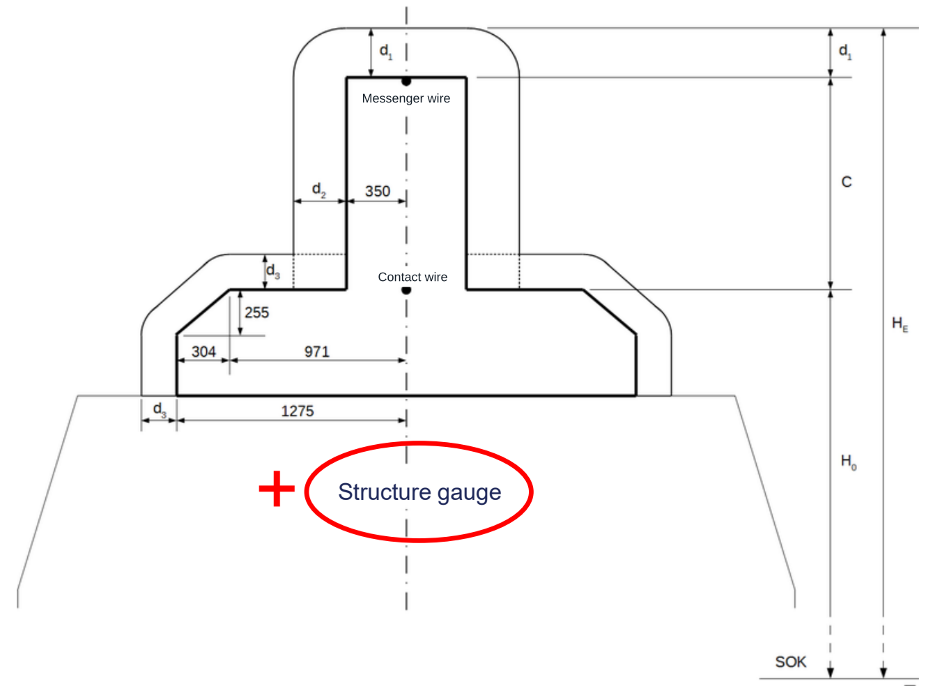
The insulation symbols distinguish three directions: \(d_1\) is above the messenger wire, \(d_2\) is sideways from the overhead-line conductors and \(d_3\) is sideways/upwards from the pantograph. Typical values in the current rules are 400 mm for \(d_1\) and 235 mm for \(d_2\), with conditional reductions for \(d_1\). For \(d_3\), distinguish 150 mm static clearance where a pantograph may stop from 100 mm dynamic clearance where stopping is unlikely. Normal contact-wire height is 5600 mm up to 200 km/h; new lines above 200 km/h use 5100 mm. Lower wire heights and reduced clearances have separate conditions. Thus the legend values cannot be applied as interchangeable safety margins [51].
14.2.5 Short Structures above the Track
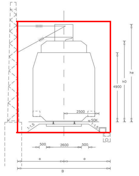
A short overhead structure and a long enclosed tunnel do not use the same normal-profile check. Bane NOR distinguishes structures shorter than 20 m along the track from structures longer than 20 m; overbridges also have their own bridge requirements. At the exact boundary, resolve the applicable provision rather than extrapolating from a lecture sketch. Figure 14.8 defines the lateral dimension \(a\) used in Table 14.1. The vertical check must allow for the selected overhead-line system and the required static electrical clearance. [51]
| Radius \(R\) [m] | \(a\) [m] |
|---|---|
| \(R<1000\) | 3.240 |
| 1000–1500 | 3.190 |
| 1500–2000 | 3.150 |
| 2000–2500 | 3.140 |
| 2500–5000 | 3.090 |
| \(R>5000\) | 3.000 |
14.2.6 Tunnel Profiles
A tunnel normal profile must also accommodate equipment, escape routes and aerodynamic requirements. It is therefore more than the train's movement envelope [51].
The single-track example in Figure 14.9 places the railway envelope within a larger tunnel section. Equipment and access space must fit outside the protected train envelope. FP denotes the formation plane and SOK the top of rail. The dimensions belong to this normal-profile example, not to every tunnel type.
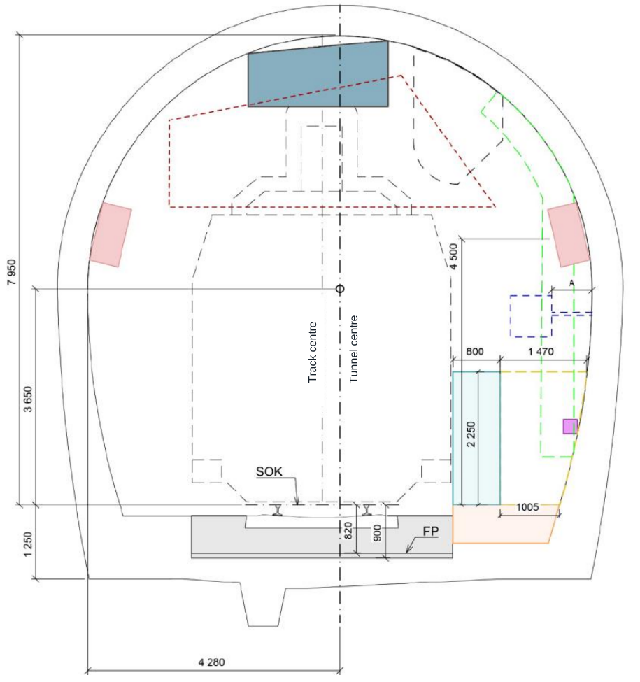
The coloured equipment areas are reservations, not spare space for the train: AT feeder cables, overhead-line supports and tensioning equipment, radiating radio cable, fans, signs, telecommunications/AV equipment, cable routes and handrails all compete for room. The illustrated walkway reservation is 800 × 2250 mm. These example dimensions do not replace the project-specific evacuation and tunnel requirements.
A circular TBM excavation changes where these functions fit. Figure 14.10 shows the railway envelope set inside a circular lining: the lower invert, walkway and overhead equipment still have to be accommodated, so the excavation diameter cannot be chosen from train height alone.
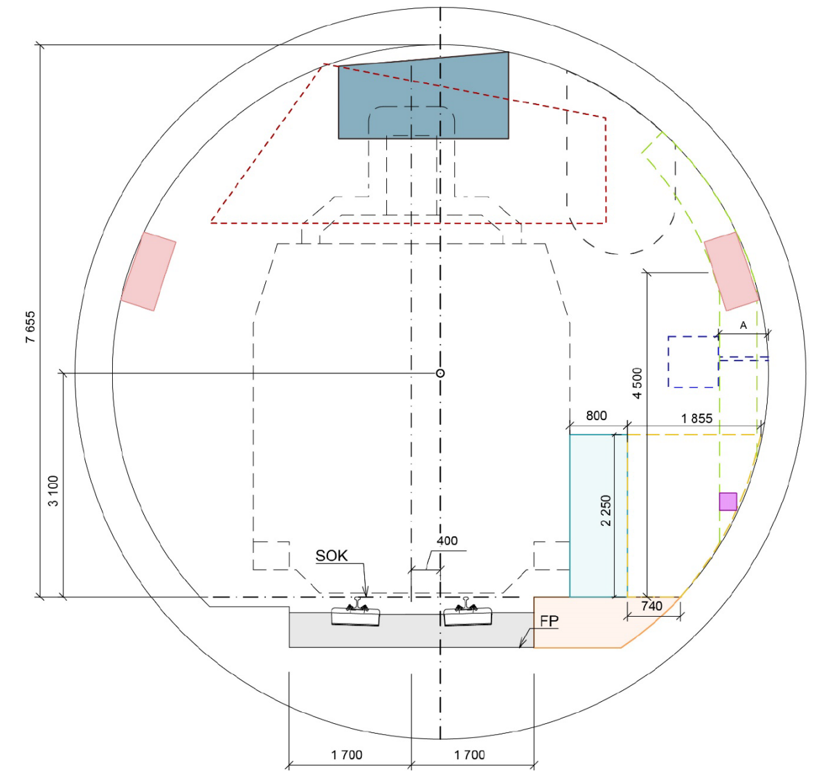
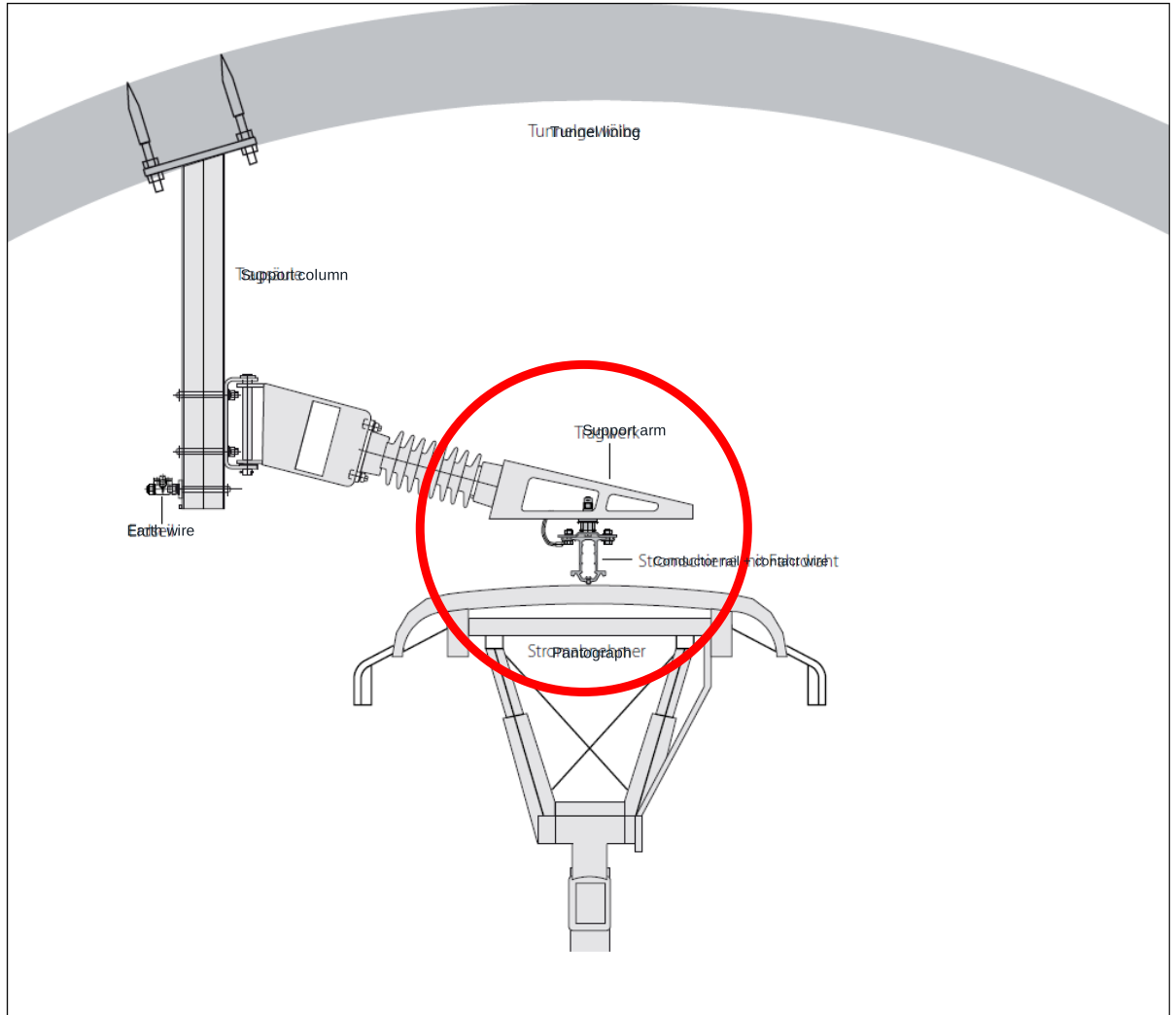
A rigid overhead conductor rail may reduce the overhead system’s construction height in a constrained tunnel. It does not remove the pantograph movement envelope or the electrical-clearance check. Its speed range, support arrangement and transition to a conventional overhead line must suit the selected system.
The support arm, conductor rail and pantograph in Figure 14.11 show where construction height can be saved. The red ellipse highlights their interface; it does not indicate a relaxation of the pantograph clearance requirements.
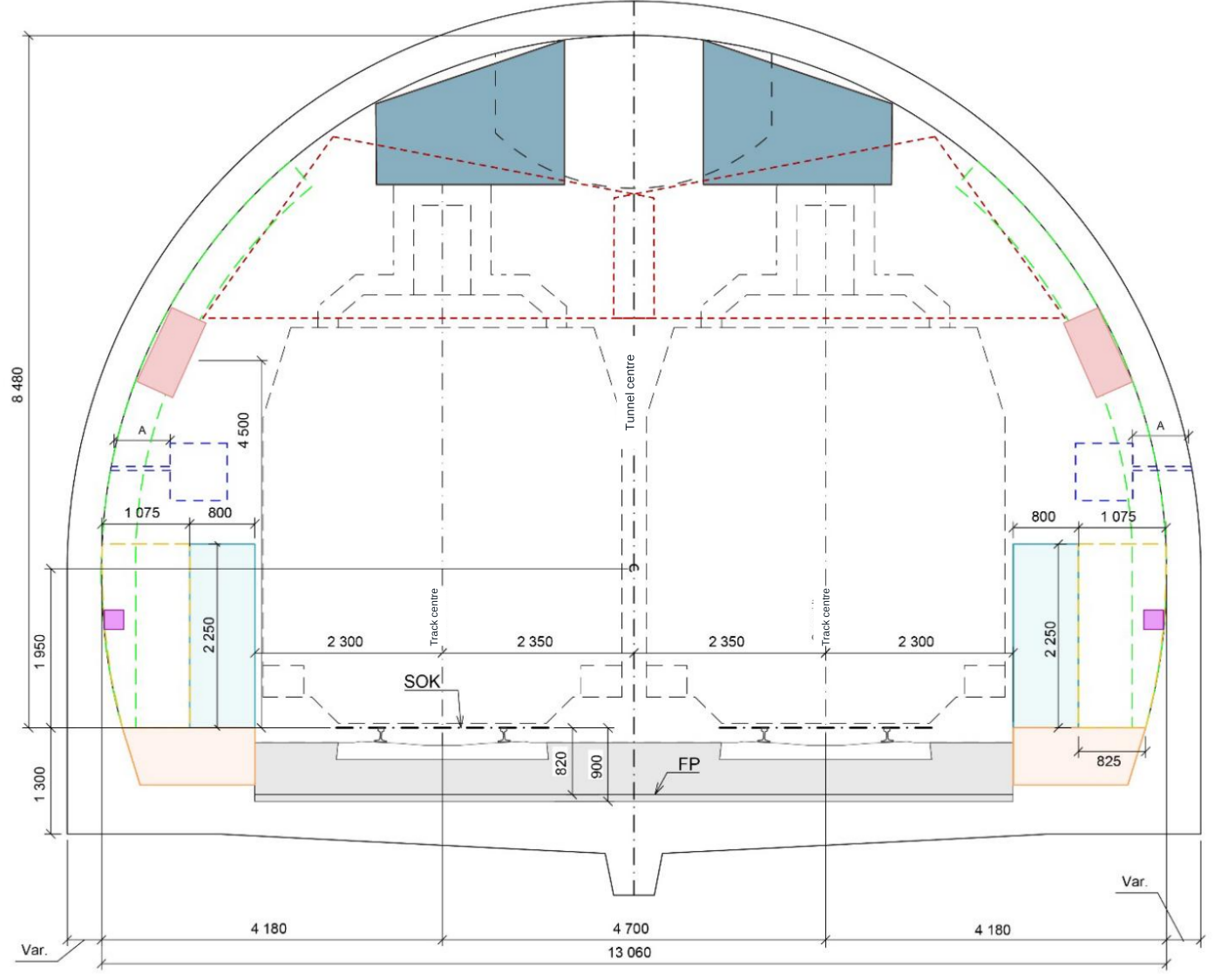
In a double-track tunnel, Figure 14.12, check both train envelopes and their separation, not simply twice the single-track width. Aerodynamic interaction, speed, safety arrangements and equipment affect the required section. The illustrated 4700 mm track spacing belongs to this example; Bane NOR specifies at least 4.7 m for the stated 200–250 km/h double-track tunnel case, while normal profiles remain project-specific [51].
International comparison also matters: British, continental European/UIC and North American loading gauges have different outlines and historical constraints. Sharing the same track gauge does not make vehicles interchangeable. A profile accepted in one country or corridor must still be checked against the complete intended route.
14.3 Curve Overthrow
Curve overthrow is the extra swept space required when a vehicle negotiates a curve. It is a central correction in gauge calculations because the vehicle body no longer remains centred over the track centre line.
14.3.1 Principle
Curve overthrow has two different horizontal components: centre throw at the middle of the vehicle body and end throw beyond the bogie pivots. Figure 14.13 shows the rigid-body chord geometry before the calculation rules are introduced.

A long vehicle in a curve takes more transverse space than on tangent track [68, 130]. The body:
-
swings inward at the midpoint between the bogies (centre throw \(K_i\)), and
-
swings outward beyond the bogies (end throw \(K_y\)).
The structure gauge width must be increased by the curve overthrow at all curved locations, including transition curves and tangent track within a certain distance of a curve [51].
14.3.2 Reference Vehicle
Bane NOR's curve-overthrow tables are based on a reference vehicle with:
-
Total length: 24 m
-
Bogie pivot distance (between bogie centres): 18 m
-
Distance from bogie pivot to car-body end: 3 m
-
Axle distance within the bogie: 2 m
14.3.3 Formulas for Existing Lines (\(R > 180\) m)
For existing lines (gauges A-85, A-96, A-96T, AC) with curve radius \(R > 180\) m, the curve overthrows are:
where \(K_i\) is the centre throw (inside) and \(K_y\) is the end throw (outside). These are conventional-unit expressions: insert \(R\) in metres; the resulting \(K_i\) and \(K_y\) are in millimetres.
For new lines (post-1990), the required width increment is given in tabulated form and includes both the geometric overthrow and the dynamic movements of the vehicle in a single combined value. In station areas on new lines, the curve overthrow is reduced by 80 mm, but the distance from the track centre line must remain at least 2200 mm between heights 760 mm and 3800 mm.
These are two different calculation cases. Outside station areas, interpolate the new-line table and round upward to a whole centimetre. Inside station areas, use the existing-line overthrow table with the stated 80 mm deduction and the 2200 mm minimum distance; do not simply subtract 80 mm from the combined new-line widening. A separate reduced-overthrow dispensation exists for specified short combined-transport vehicles in A-96 above 3440 mm. It is not a general reduction for every vehicle or for the whole profile [51].
Table 14.2 makes the outside-station new-line case explicit. Its \(k\) is a combined geometric/dynamic width addition; it is not an extra term to add on top of the same movements again. Values between the tabulated radii are interpolated and rounded upward to a whole centimetre.
| \(R\) [m] | \(k\) [mm] |
|---|---|
| Tangent | 0 |
| 20000 | 0 |
| 10000 | 0 |
| 5000 | 80 |
| 4000 | 100 |
| 3000 | 120 |
| 1000 | 120 |
| 600 | 130 |
| 500 | 140 |
| 300 | 150 |
The reduced A-96 case in Table 14.3 is a restricted dispensation basis for short combined-transport vehicles: the reference combinations are 13.5 m axle/pivot spacing with 2.0 m overhang, or 10.0 m spacing with 3.0 m overhang. It applies only above 3440 mm in A-96. The lecture highlights secondary/siding use; in every case the infrastructure manager must establish that the dispensation and the actual vehicle/route are covered. These values do not replace the ordinary A-85/new-line calculation.
| \(R\) [m] | \(K_i\) [mm] | \(K_y\) [mm] |
|---|---|---|
| 200 | 114 | 98 |
| 250 | 91 | 78 |
| 300 | 76 | 65 |
| 400 | 57 | 49 |
| 500 | 46 | 39 |
| 600 | 38 | 33 |
| 700 | 33 | 28 |
| 800 | 28 | 24 |
| 900 | 25 | 22 |
| 1000 | 23 | 20 |
| 1200 | 19 | 16 |
| 1500 | 15 | 13 |
| 2000 | 11 | 10 |
| 5000 | 5 | 4 |
| 8000 | 3 | 2 |
14.3.4 Curve Overthrow in Transition Zones
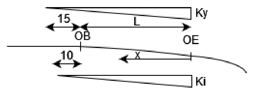
At locations where the radius changes (transition curves, tangent track near a curve end), the overthrow is interpolated linearly:
where \(L\) is the transition curve length and \(x\) is the distance from the end of the transition curve to the calculation point. Insert \(L\), \(x\), and the constants 10 and 15 in metres; \(K_{ir}\) and \(K_{yr}\) are the full adjacent-curve overthrows in millimetres, so \(K_i\) and \(K_y\) are also in millimetres.
Figure 14.14 shows how the full curve allowances taper through the transition and into the adjacent tangent. OB and OE mark the beginning and end of the transition curve; the 10 m and 15 m reaches belong to the two different allowance cases above.
14.3.5 Vertical Curve Overthrow
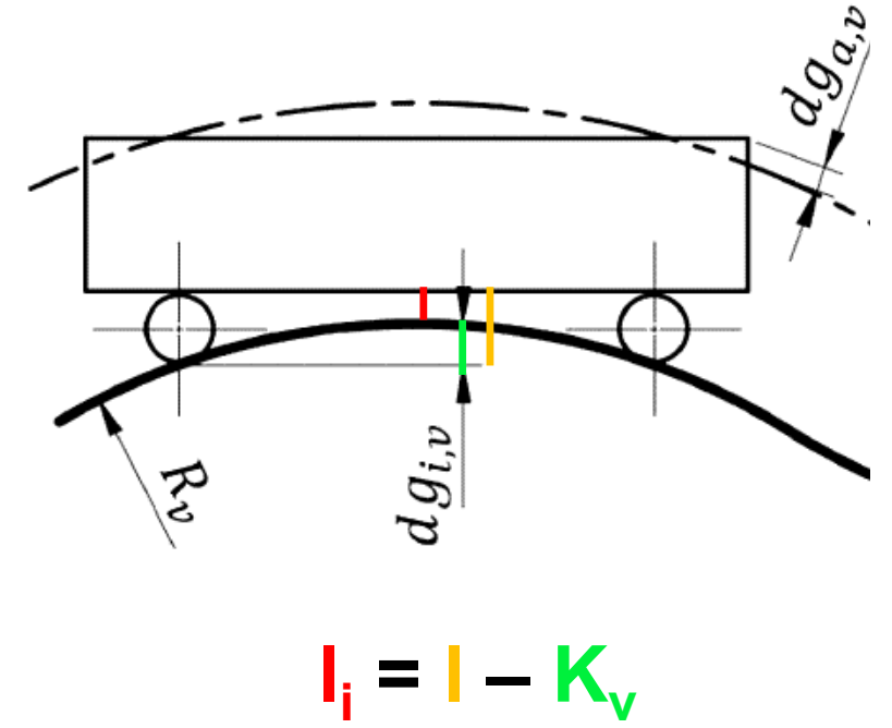
In vertical curves with radius \(R_v < 1500\) m, a vertical curve overthrow must also be calculated for all heights:
This is a conventional-unit expression: insert \(R_v\) in metres; the constant 27 and the resulting \(K_v\) are in millimetres. The effective clearance dimension is reduced: \(l_i = l - K_v\).
The crest geometry in Figure 14.15 explains the subtraction: the vehicle spans the vertical curve, so the available clearance is reduced by the vertical overthrow. The coloured dimensions identify the original clearance and its reduced value.
14.3.6 Worked Example: Curve Overthrow
Example: An existing line has a horizontal curve with radius \(R = 500\) m. Calculate the centre throw and end throw for the Bane NOR reference vehicle, and then calculate the reduced overthrow at a point in the adjacent transition zone where \(L = 80\) m and \(x = 30\) m.
Full overthrow in the circular curve:
The structure gauge must therefore be widened by about 81 mm on the inside at the vehicle midpoint, and by about 63 mm on the outside beyond the bogie pivots.
Reduced overthrow in the transition zone:
At this point in the transition zone, the required widening is smaller than in the circular curve, but it is still not zero. The check must therefore use the local value of the overthrow rather than the circular-curve value alone.
Vertical curve check: If the same location also has a vertical curve with \(R_v = 1000\) m, the vertical curve overthrow is:
The available vertical clearance dimension is then reduced by approximately 14 mm: \(l_i = l - 14\,\text{mm}\).
14.4 Track-Level and Trackside Clearance
Clearance checks also apply to low objects, snow-clearing equipment, staff working beside vehicles and openings through which vehicles pass.
14.4.1 Flangeways and Low Fixed Structures
Clearance is needed between the rails as well as beside and above the train. Bane NOR's ordinary flangeway requirement is \(R_b=70\) mm for track gauge up to and including 1445 mm; above that, \(R_b=\text{track gauge}-1375\) mm. Special rules apply to crossings, turnouts and level-crossing surfaces. Permitted low-level intrusions are conditional exceptions, not permission to fill the space between the rails.
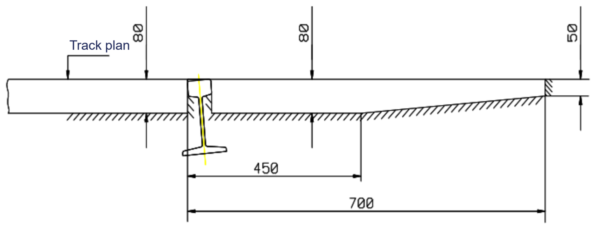
In the lower-profile drawing, a identifies the conditional limits for crossing surfaces and turnout check rails, b for fixed objects in station tracks, and c for check rails in obtuse crossings of diamond slips. The exceptions apply only beyond the specified lateral offsets and do not apply where the vertical-curve radius is 1500 m or less. Check the complete conditions in TRV:00757 [51].
Figure 14.16 identifies the flangeway width \(R_b\) beside the running rail. Figure 14.17 then shows the track-plane boundary and the conditional exceptions labelled a, b and c. These different height limits apply to specified installations and must not be treated as a general raised floor between the rails.
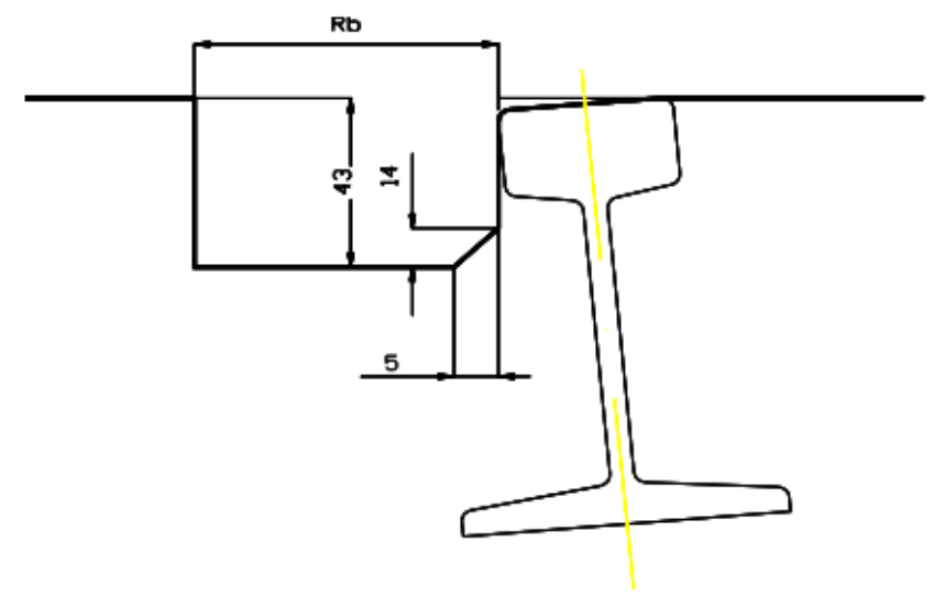
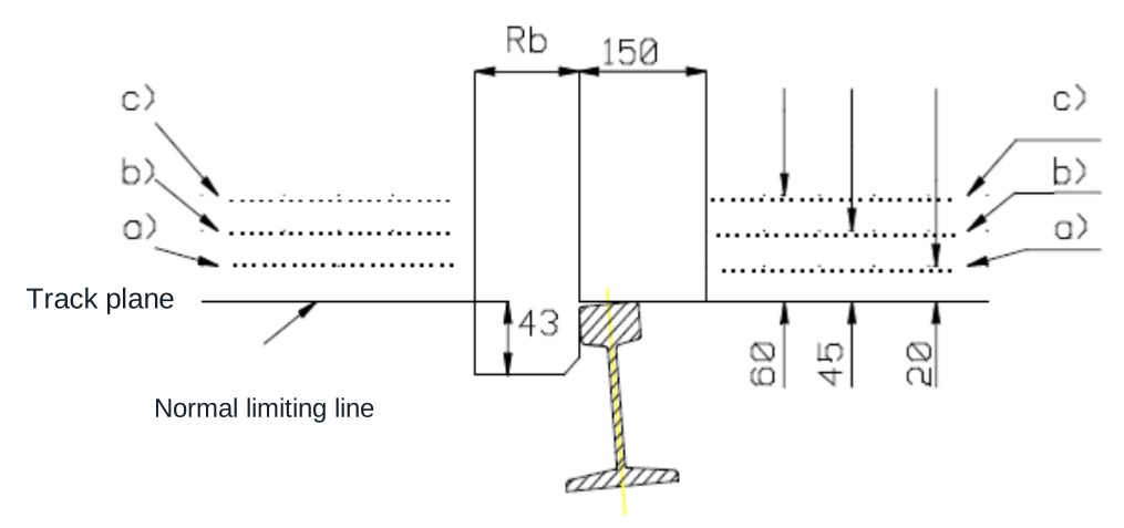
The ordinary flangeway rules also require 100 mm at the end of a flangeway in a timber-deck level crossing. Reduced widths may be permitted for turnout check/wing rails, crossings, track brakes and level-crossing rubber strips; these are component-specific exceptions. Components forming the inner flangeway edge must be secured so the width cannot close up. In the low-profile drawing, a corresponds to the 5–20 mm crossing-deck case or a check-rail top up to 20 mm, b to fixed station-track constructions up to 45 mm, and c to check rails in obtuse crossings of slip turnouts up to 60 mm. Between the rails, the exceptions start beyond \(R_b\) from the gauge face; outside the rail they start beyond 150 mm. The vertical-curve exclusion remains applicable [51].
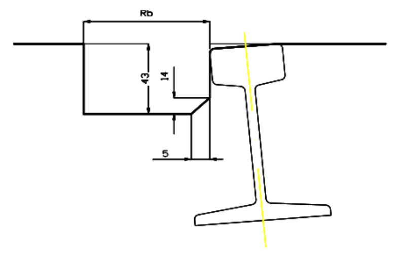
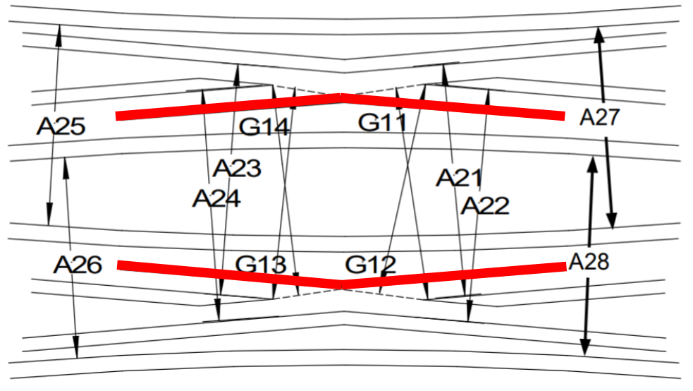
Flangeway details must be checked at special trackwork as well as beside a plain rail. Figure 14.18(a) shows a special low-level section, 14.18(b) locates the crossing checks in plan, and 14.18(c) shows the corresponding narrow rail gap. The section dimensions describe the illustrated detail, not a general replacement for the applicable flangeway requirements.
(a) Low-level section
(b) Crossing geometry and check locations
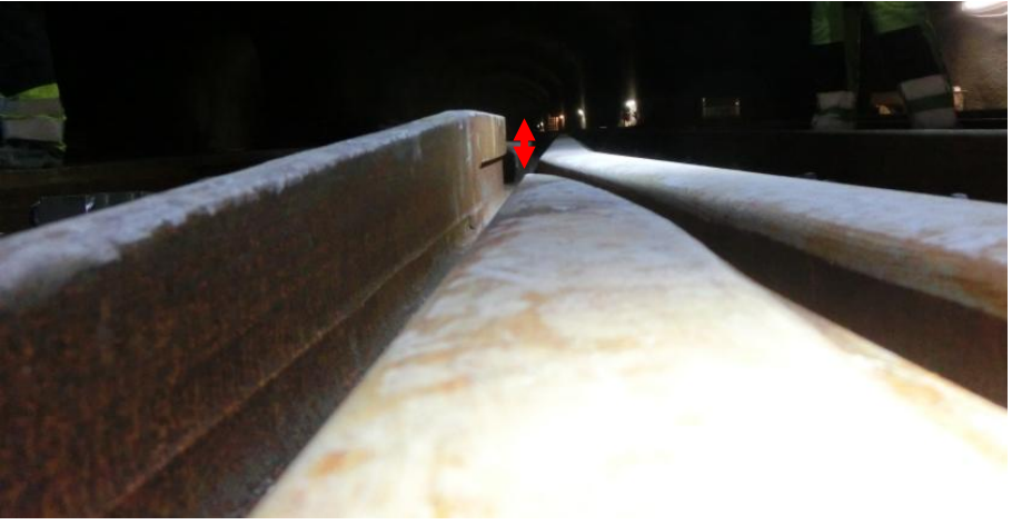
(c) Gap between the rails
14.4.2 Snow-Scraper Clearance
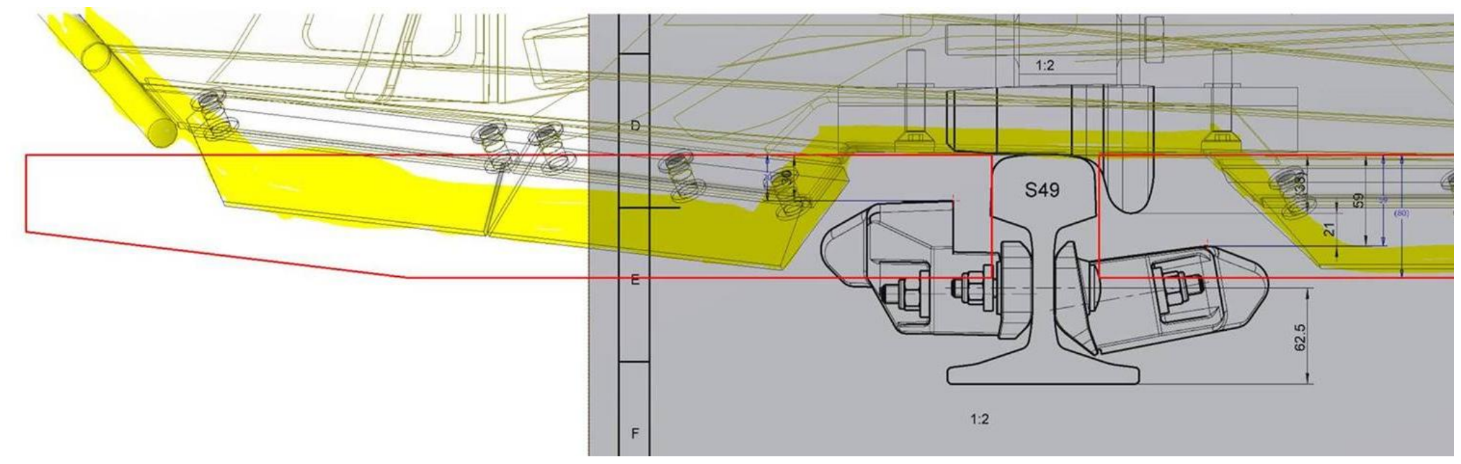
A track snow scraper works below and beside rail level. Figure 14.19 shows why its required free space differs from the train-mounted plough profile: fixed objects must be checked against the scraper outline as well as the ordinary vehicle envelope. Apply the scraper requirements for the route and installation concerned.
Where a fixed installation requires the scraper to be raised, the open line must be marked for raising/lowering the scraper. Axle counters illustrate the interface: a permitted signalling installation can still conflict with snow-clearing equipment unless its position and the scraper recess/operating arrangement are coordinated. [51]
Figure 14.20 overlays the scraper outline and an axle-counter installation. The recess around the detector illustrates why equipment must be checked against the scraper envelope as well as the wheel and rail geometry.
14.4.3 Shunting Areas and Trackside Equipment
Trackside design must also leave room for staff and future track adjustment. In shunting areas, the specified extra clearance beside tall objects protects shunting staff. Elsewhere, allow for lateral and vertical track maintenance before placing cabinets, signals or masts. Door openings and loading equipment have separate conditional rules; a depot opening is not automatically suitable for every train allowed on the adjoining line. Apply the detailed requirements in TRV:00754–00769 to the actual installation [51].
The extra side space in Figure 14.21 protects staff beside a vehicle during shunting. It is additional to the train-passage envelope, not an allowance that can be used to accommodate a wider load. Equipment siting must also preserve the specified room for future track adjustment.
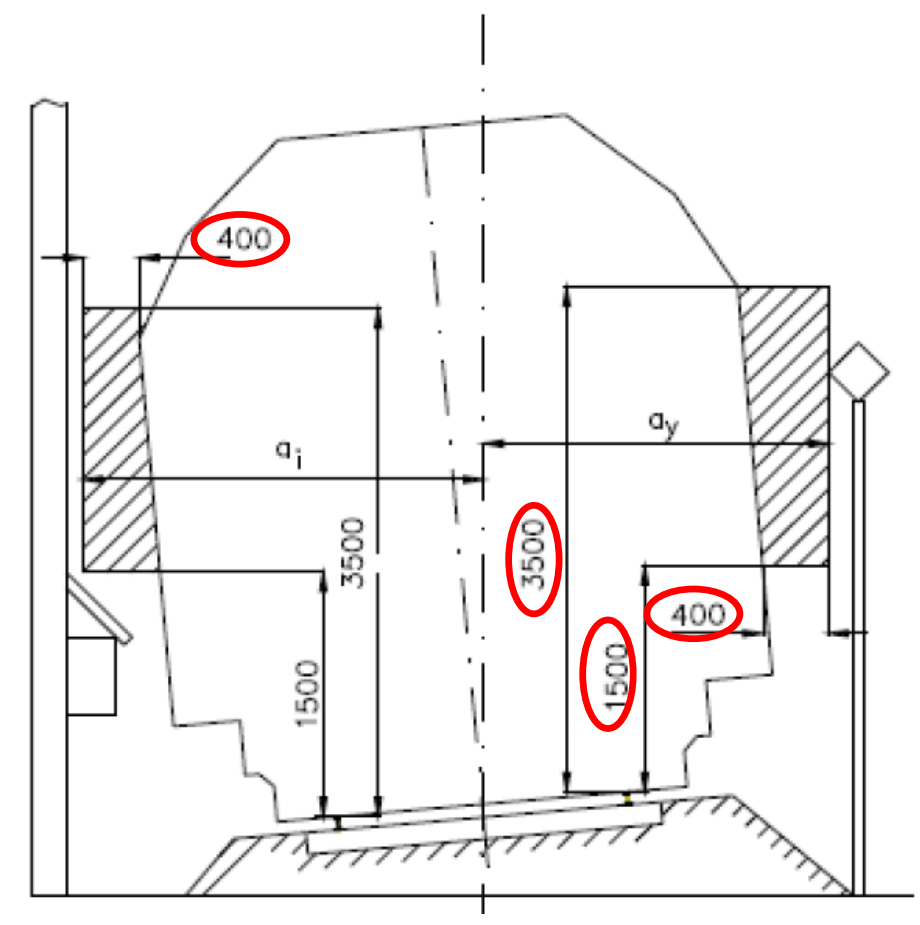
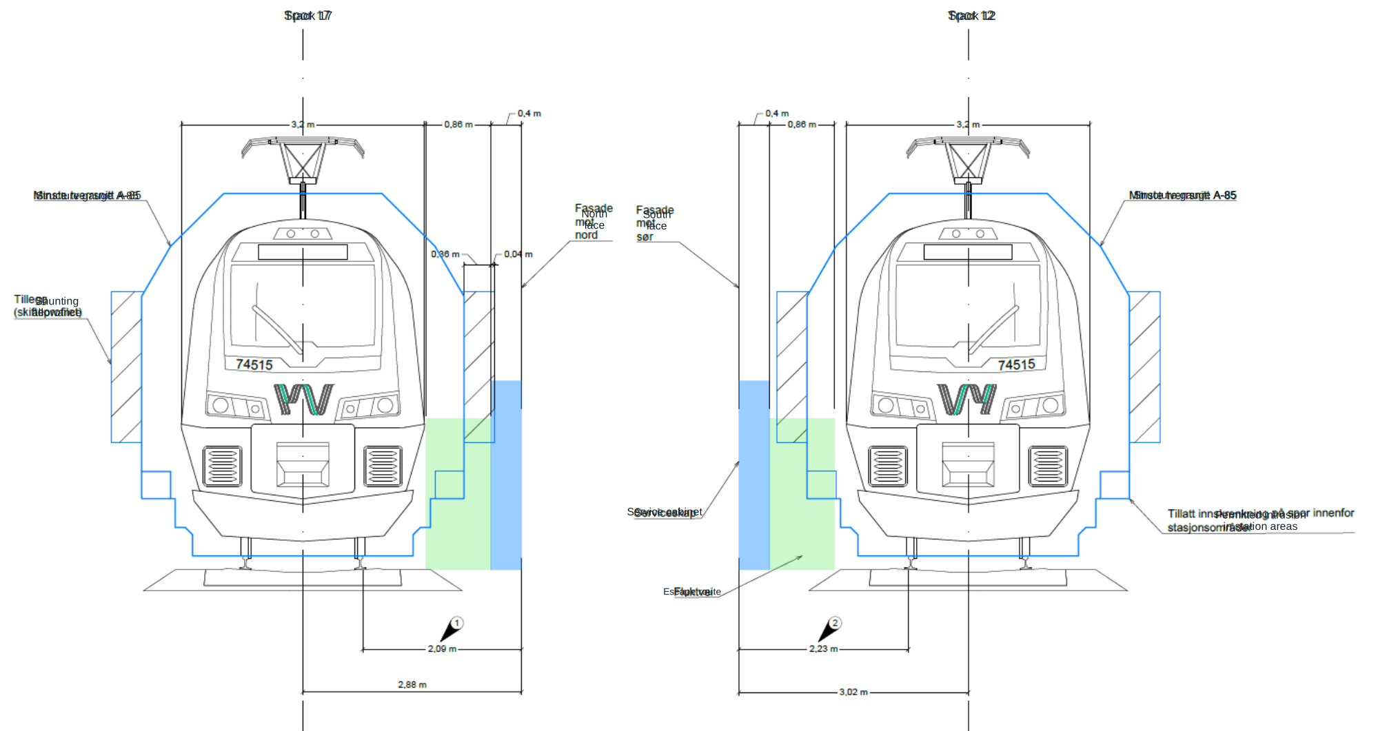
For the illustrated A-85/A-96/A-C shunting case, tall objects normally need 400 mm beyond the structure gauge in the height band 1500–3500 mm above the nearest rail. With cant \(h\) in millimetres, the drawing’s distances from track centre are:
These are infrastructure-side siting distances, not the vehicle-body displacement formulas used later. Conditional encroachments require the prescribed warning marking. Cabinets and service platforms, such as the Lodalen example discussed in the lecture, must be checked together with train passage, staff access and maintenance. Outside shunting areas, the track-adjustment allowances in Table 14.4 protect the clearance when the track is moved or maintained.
| Track adjustment | Allowance [mm] |
|---|---|
| Lateral slewing | 100 |
| Lifting | 50 |
| Lowering | 20 |
| Cant change | 20 |
For an object below 1120 mm above the track plane, the lateral-slewing allowance may be reduced to 30 mm under the stated rule. Do not call the 50 mm allowance “tamping”: tamping is a maintenance operation, whereas the clearance allowance is for the resulting track lift.
The Lodalen example in Figure 14.22 puts the service cabinet and escape route between two vehicle envelopes. The two track sides must be checked separately: cabinet faces, shunting allowances and the permitted station-area intrusion do not form one interchangeable clearance. The dimensions document this particular arrangement.
14.4.4 Door Openings and Loading Installations
Figure 14.23 shows a door opening measured about the track centre. The inside- and outside-curve additions, \(K_i\) and \(K_y\), act on different sides of the opening. Its clear size must suit the actual vehicle, load and track geometry. Loading equipment has its own conditional clearances and operating positions; a compliant door alone does not establish route compatibility.
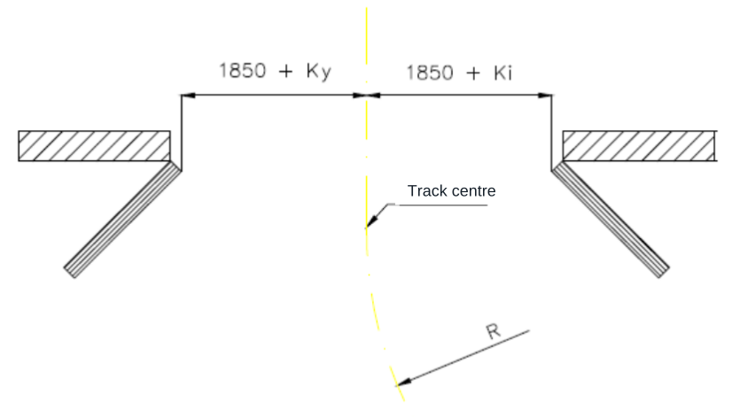
The ordinary opening is at least 3700 mm wide on tangent track, widened by the applicable inside/outside overthrow in or near a curve. Door height is normally at least 5600 mm; 4800 mm is the conditional case where electrification is not relevant. The full structure gauge is required where the track through the building is the only connection to tracks beyond it, or where out-of-gauge consignments must be received. This is more specific than simply calling every such track a through-track.
Loading flaps and other movable parts may occupy the structure gauge only under the applicable loading-installation conditions. After loading they must be secured outside the gauge, with the required securing where the installation faces a train-running track. Permanent intrusion is a separate permitted case for tracks used only for specified loading operations, not a general terminal exception [51].
14.5 Track Centre Distance at the Fouling Point
At the rear of a turnout, the reference point is the clearance cross-section where the swept envelopes of vehicles on neighbouring tracks just cease to conflict. It is not the crossing nose or another turnout component. Figure 14.24 shows the centre-line distance check used at this point: the structure-gauge half-width from one track, the adjacent loading-gauge half-width, construction tolerance and any curve or cant additions must fit between the two track centres [55].
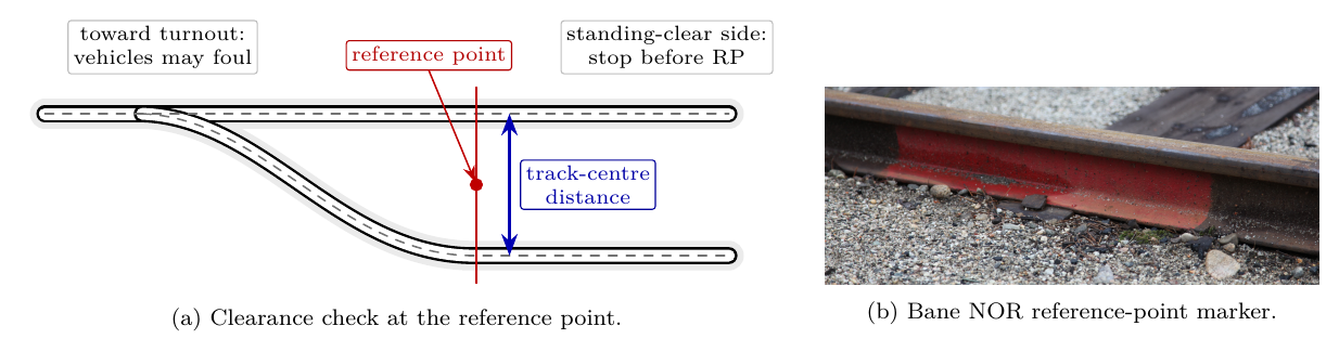
The reference point (RP, also called the fouling or clearance point) is the location at the rear end of a turnout where the distance between adjacent tracks has become large enough for rolling stock to pass safely. A train standing on the siding or loop must stop before this marker; beyond it, the vehicle envelope may foul the route used by a passing train. Bane NOR specifies that the check is based on the loading gauge on one track, the structure gauge on the other track, a 100 mm clearance, and the relevant curve and cant additions for both tracks [55].
The minimum track centre distance \(S\) at the reference point is:
For the standard case without cant and without curve overthrow:
where 2120 mm is the structure-gauge half-width from track 1 centre line to the structure envelope edge (the half-width of the A-85 profile in its widest height band) and 1700 mm is the half-width of the static loading-gauge envelope used for the vehicle on the neighbouring track, measured from track 2 centre line. Together they represent the minimum space needed from each track centre line to the interface point.
Table 14.5 gives the calculation forms used by Bane NOR for the common straight and curved-track combinations at the reference point. The table is a calculation checklist for the track-centre distance at the reference point; it does not replace the underlying structure-gauge and loading-gauge checks.
The sketches in the first five rows locate the two tracks and the distance being checked. Use each sketch with its own row; the sixth, inside/inside case is given separately in the calculation forms.
| Track arrangement at the reference point | Distance to check | How to read it |
|---|---|---|
Straight tracks, or no curve/cant addition needed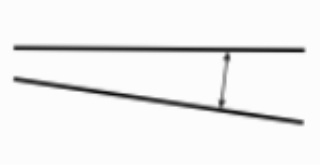 |
\(S\) | Use the base sum of profile half-widths and 100 mm clearance. |
One track requires outside-curve allowance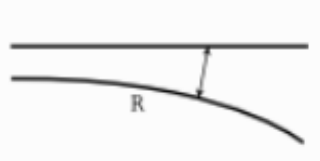 |
\(S + K_y\) | Add the end-throw allowance for the track on the outside of the curve. |
One track requires inside-curve and cant allowance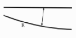 |
\(S + K_i + 2.3h\) | Add centre throw and the cant-related lateral addition for the curved track. |
One track uses inside-curve allowance and the other uses outside-curve allowance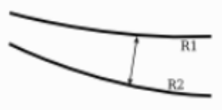 |
\(S + K_i + K_y + 2.3\lvert h_2-h_1\rvert\) | Add both curve allowances and the cant-difference allowance between the two tracks. |
Both tracks require outside-curve allowance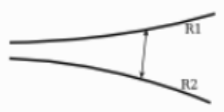 |
\(S + K_y(R_1) + K_y(R_2)\) | Use the end-throw allowance for each neighbouring track's radius. |
| Both tracks require inside-curve allowance | \(S + K_i(R_1) + K_i(R_2) + 2.3(h_1+h_2)\) | Use each track's radius and the cant additions for this particular arrangement. |
Here \(K_i\) is the inside-curve centre-throw allowance, \(K_y\) is the outside-curve end-throw allowance, and \(h\), \(h_1\) and \(h_2\) are the cant-related quantities used in the corresponding Bane NOR calculation case. Insert the cant-related quantities in millimetres; the coefficient 2.3 is dimensionless, so its lateral allowance is also obtained in millimetres. If neither track is a through-track, Bane NOR permits the base value to be reduced to 3720 mm. On new lines where at least one of the two tracks is a through-track, the calculated distance at the reference point shall not be less than 4000 mm [55].
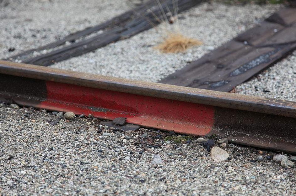
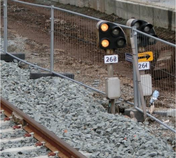
The field examples in Figure 14.25(a) and 14.25(b) show a rail-mounted marker and a marker beside a ground signal. In both cases the marker communicates the clearance location to operating staff; the calculation is still based on the two tracks and their vehicle envelopes.
14.6 Loading Gauges and Vehicle Profiles
Having defined the available infrastructure space, the next step is to identify the transport and rolling-stock profiles to be checked inside it.
Three transport families explain why different parts of the outline matter:
- Wagonload traffic: closed wagons and timber loads. Timber can govern the shoulders around 4.0–4.2 m above rail even when overall height is acceptable.
- High or double-deck vehicles: car carriers and double-deck passenger stock. Their roofs and upper corners challenge both the infrastructure contour and the overhead-line clearance.
- Combined transport: containers, swap bodies and semi-trailers on suitable wagons. Wide upper corners can govern around 4.4–4.5 m above rail in the lecture examples. Unit dimensions and the wagon’s loading height must be considered together.
These height bands describe the illustrated transport cases, not universal limits for every vehicle.
14.6.1 Loading Gauges and Transport Codes
The second question is a vehicle question: which rolling-stock body or freight load can pass through the empty space provided by the infrastructure? In simple terms, the structure gauge is the clear opening that the railway must keep free of obstacles, while the vehicle profile or loading case is the shape that is placed inside that opening during a gauging check. A named loading case is therefore not the actual wagon itself, but a standard envelope representing a wagon plus its load, including the relevant geometric allowances.
The terminology in Table 14.6 is easy to confuse, because it mixes the infrastructure side and the train/load side of the same compatibility check:
- Structure gauge
-
The infrastructure envelope that must be free of fixed objects such as platforms, signals, tunnel walls and electrification equipment.
- Reference profile
-
A standard rolling-stock envelope used in gauging calculations. Norwegian NO1 and NO2 are dynamic reference profiles, as illustrated in Figure 14.28.
- Loading gauge or loading case
-
A standard envelope for a freight wagon and its load. The case says, for example, how high and wide a container, swap body or semi-trailer may be when carried on a specified type of wagon. G1, GA, GB and GC are named European vehicle/load envelopes; GA, GB and GC are mainly used for freight and combined transport, with GC the largest of these three. C/P 410 is a combined-transport code: C means container or swap body, P means semi-trailer, and 410 identifies the associated coded contour; its meaning depends on the unit category and wagon, rather than being the total height of every load above rail [42, 55].
For combined transport, read a C/P code together with the loading-unit width, wagon characteristics and the route's current codification. It is not an unrestricted overall height above rail. Likewise, GC and NO1 have different contour shapes: a profile that gives more clearance at the upper corners need not be wider at every height. Timber loads, containers and double-deck vehicles therefore require different checks.
The lecture’s narrower/wider coding distinction is important, but the width threshold must be matched to the unit type. For P-coded semi-trailers, two-digit codes cover widths up to 2.50 m and three-digit codes the wider class up to 2.60 m. C-coded containers and swap bodies have their own conditions: do not transfer the semi-trailer’s width breakpoint to every C-coded unit. The digits are not a dimension to apply without the associated coding rules. Check the unit code, carrier-wagon compatibility/correction marking and route code together. Container/swap-body and semi-trailer codes are not interchangeable merely because the number looks the same [259].
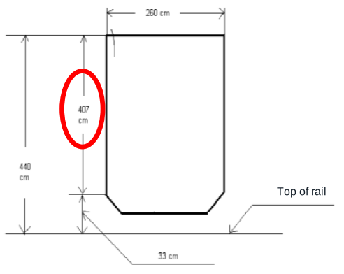
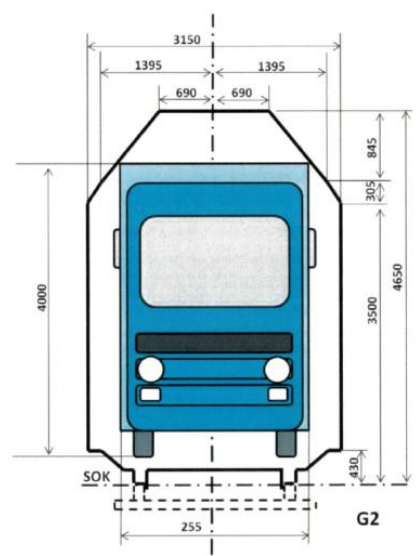
Worked example: P407. Figure 14.26(a) shows a rectangular semi-trailer contour 4070 mm high and 2600 mm wide, carried with the illustrated lower reference/loading level 330 mm above rail. The resulting top is \(4070+330=4400\) mm above rail. The P407 number does not mean a 4070 mm total height above rail. Figure 14.26(b) shows why a rectangular road-vehicle load must also fit the shoulders of the surrounding railway profile. The 330 mm level belongs to this wagon/load example; another carrier or loading arrangement requires its own coding and compatibility check [55].
Route maps and approval. The two maps in the lecture distinguish loading-unit width classes; a route code must be read in the correct class and for the current timetable period. Use the profile section and linked route maps in the current Network Statement rather than treating a copied historical map as transport approval. Check the complete journey, including terminal access, diversions and any local restrictions [258].
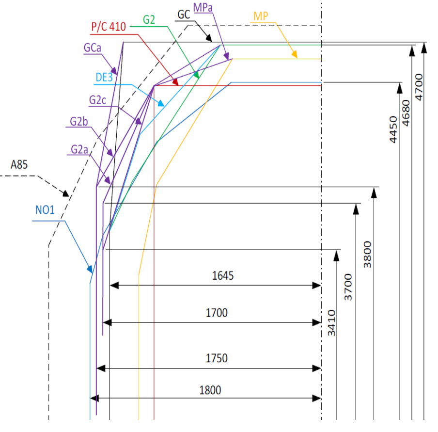
International profile families. G1, GA, GB and GC describe standardised outlines, not a universal ladder of permissions on every railway. The lecture also mentions GB+ and related freight variants. Wider upper shoulders can admit a different container/load combination without making the profile wider at all heights. Figure 14.27 compares labelled international and Norwegian contours, including G2 variants, NO1, MP and P/C 410. Read each contour together with its defining rules. Bane NOR’s current route information identifies the accepted international profiles and any combined-transport restrictions [258].
14.6.2 Norwegian Vehicle Reference Profiles
The Norwegian reference profile NO1, shown in Figure 14.28(a), is a dynamic gauge defined in accordance with EN 15273 and valid for all lines on the national network that are open to ordinary traffic [51, 68]. Profile NO2, shown in Figure 14.28(b), is a supplementary dynamic gauge for bi-level passenger coaches and timber wagons. Both are described in Bane NOR technical regulations [51, 26].
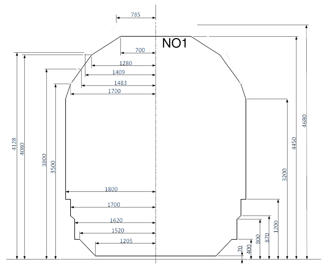
NO1 standard dynamic reference profile.
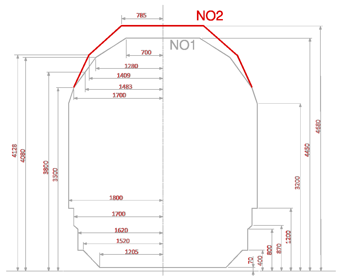
NO2 supplementary dynamic reference profile.
The compatibility table below uses NO1 and NO2 for the Norwegian dynamic rolling-stock reference profiles, and MP for the multipurpose profile for high bi-level wagons or bi-level passenger vehicles where contact-line insulation clearance permits.
Figure 14.29 compares the upper contours of GC and NO1 against the A-85 boundary. GC reaches higher, whereas NO1 is wider at some lower heights. Compatibility is therefore a contour-by-contour check, not a choice of whichever profile has the greatest overall height.
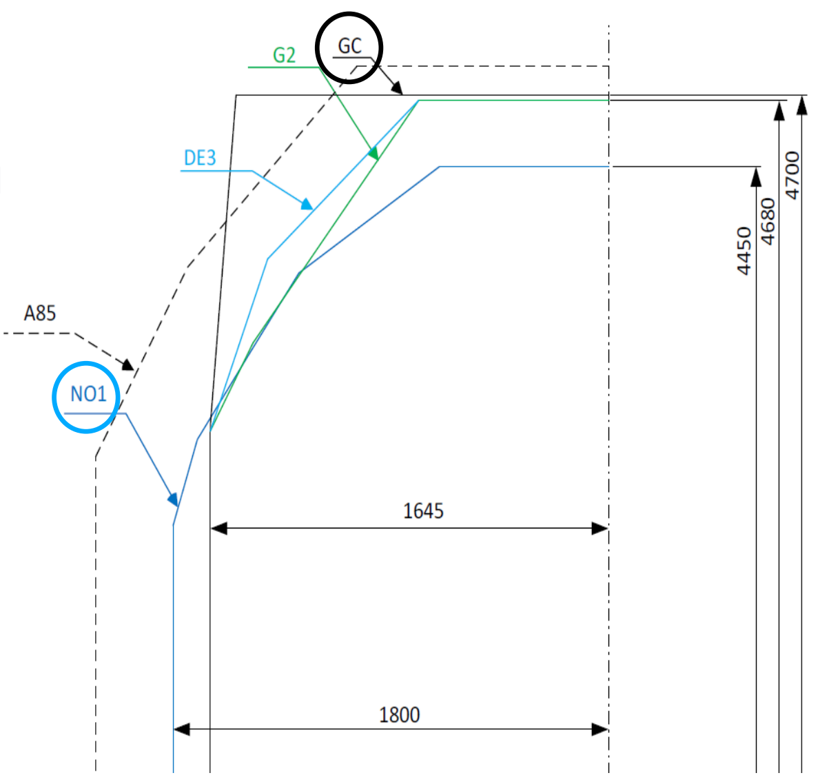
Do not extend NO1’s network applicability to NO2, MP or GC without checking the route. NO2 is a supplementary dynamic case for specified traffic and routes. MP is a vehicle-profile case for high bodies such as car carriers and double-deck stock; the electrical clearance to the contact line can govern even where the civil structure clears the roof [258].
14.6.3 Infrastructure and Vehicle Compatibility
- Permitted profile in the table
-
A profile or loading case that is normally compatible with the listed infrastructure gauge. It is a screening result, not automatic route approval.
Bane NOR presents the relationship as a screening table: first identify the infrastructure gauge on the route, then check which vehicle/load envelope is normally intended to fit inside it. Local restrictions, measured route profiles, curve overthrow, pantograph clearance and vehicle simulations still govern the final decision [42].
| Structure gauge | Vehicle/load envelope tested inside it | Meaning for a route check |
|---|---|---|
| A-85 (existing) | NO1, G1, GA, GB and MP where contact-line insulation permits | Basic existing-line clearance. It may carry ordinary rolling stock and several standard freight profiles, but high or wide vehicles still require local route checks. |
| A-96 (existing) | C/P 410 combined transport | Existing-line gauge with extra upper-corner clearance for selected container and semi-trailer traffic. |
| A-96T (existing) | No separate loading case is listed in Bane NOR's summary table | Top-profile variant of A-96. Use it only with an explicit check of the relevant freight wagon, double-deck passenger vehicle or other vehicle case. |
| AC (A-C, existing) | UIC GC | Existing-line gauge intended for the large GC freight envelope. It still requires route-specific simulation and clearance checks. |
| New-line structure gauge | All listed profiles/loading cases, subject to route approval | Broadest standard infrastructure envelope. It gives the best starting point, but approval still depends on the measured route and vehicle/load case. |
The table is an initial compatibility guide. Final acceptance must be based on the measured route profile and the applicable vehicle, load, curve, platform and electrification checks.
The key idea is therefore a nesting check: the selected vehicle/load envelope must remain inside the infrastructure gauge after the required allowances have been added. If it does not, the route needs restrictions, a different wagon/load case, or physical infrastructure work.
14.7 Horizontal Space Requirements
The previous sections define the nominal gauge envelopes. This section explains how vehicle motion, suspension clearances, cant effects, and curve geometry enlarge the space that must be reserved in practice.
14.7.1 Overview of Influencing Factors
The space a vehicle actually requires in service is significantly larger than its static body profile. The main contributions are:
-
Suspension movements under static and dynamic loading.
-
Failed or degraded suspension components.
-
Eccentric payload.
-
Cant excess or cant deficiency causing the body to tilt inward or outward.
-
Centre throw and end throw (curve overthrow).
-
Cross-wind sway.
-
Wheelset lateral play in the rail (\(\sigma = 27.5\) mm).
-
Bogie-to-wheelset lateral play (\(q = 5\)–\(6\) mm).
-
Car-body-to-bogie lateral play (\(w = 60\)–\(65\) mm).
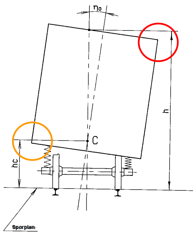
The roll examples in Figure 14.30(a) and 14.30(b) distinguish cant excess from cant deficiency. Cant excess tends to roll the body inward; cant deficiency tends to roll it outward. The roll centre and suspension response determine the extra lateral displacement at the height being checked.
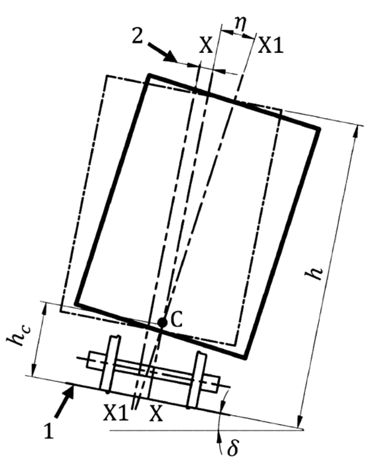
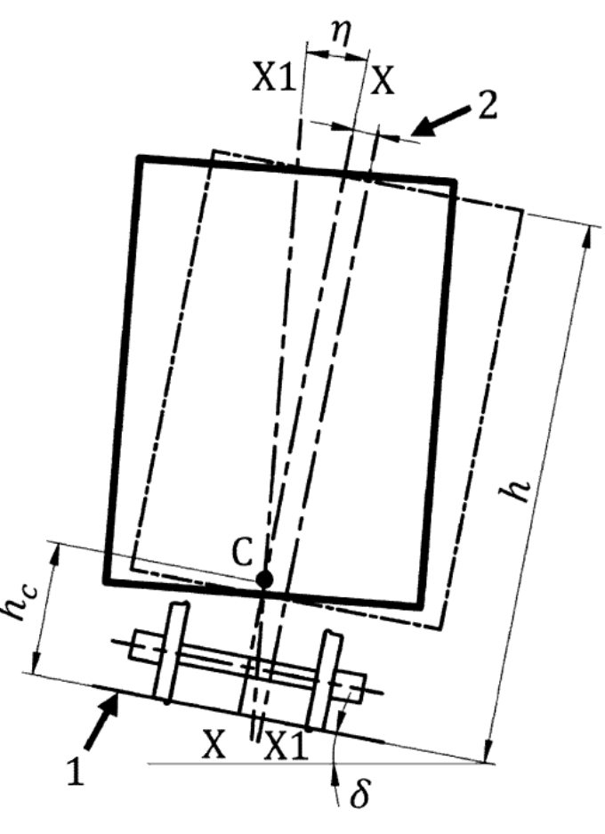
In both drawings, \(C\) is the roll centre and \(h_c\) its height above the track plane. The angle \(\delta\) describes the inclination of the track plane, whereas \(\eta\) is the additional body roll. Callout 1 identifies the track plane; callout 2 marks the lateral displacement at an upper body point. This is why the roll contribution grows with height above the roll centre.
Wheel Wear, Vehicle Geometry and Track Condition
Vehicle height, overall length, bogie-pivot spacing and the overhang beyond each pivot determine where a clearance maximum occurs. The symbols \(a\), \(n_i\), \(n_a\) and \(p\) describe different longitudinal dimensions and must not be substituted for one another. A body point between the pivots and a point beyond a pivot have different lever arms. Wheel/rail wear and gauge widening alter lateral play; track alignment errors, elastic track displacement and vertical defects change the relative track–vehicle position.
Unequal wheel wear can pitch the body longitudinally or tilt it across the track, while uniform wear lowers it. An end point can move more than the displacement at a bogie. Active tilting, suspension failures, spring misadjustment and eccentric loads need their specified operating or degraded cases. They are not automatically represented by simply adding every worst-case number in one direction.
Primary and Secondary Suspension
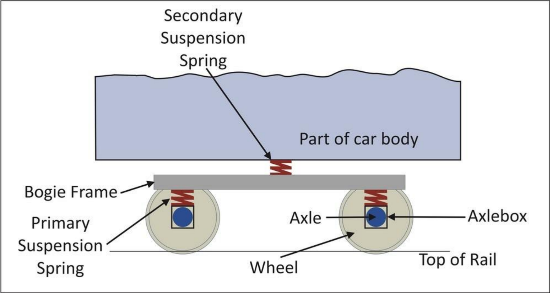
Figure 14.31 separates the primary suspension, between the wheelset/axlebox and bogie frame, from the secondary suspension, between bogie and car body. Both can contribute vertical displacement, but their motions and lateral clearances are distinct. In the vertical formulas, \(\Delta h_1\) and \(\Delta h_2\) are the primary- and secondary-suspension deflections; \(q\) and \(w\) describe the corresponding lateral-clearance interfaces, not these vertical deflections.
Roll-Angle Coefficient and Roll-Centre Height
For the quasi-static cant illustration in Figure 14.32, the flexibility coefficient is \(s=\rho/\beta\): body roll \(\rho\) relative to the track plane divided by the track inclination \(\beta\), using the same angular units. The body-roll angle is called \(\eta\) in the preceding drawings. This definition is not a rule that running body roll depends on cant alone: the calculation must use the relevant cant excess or deficiency and the vehicle’s suspension characteristics. The teaching range \(s=0.150\)–\(0.225\) is not a universal specification for all rolling stock.
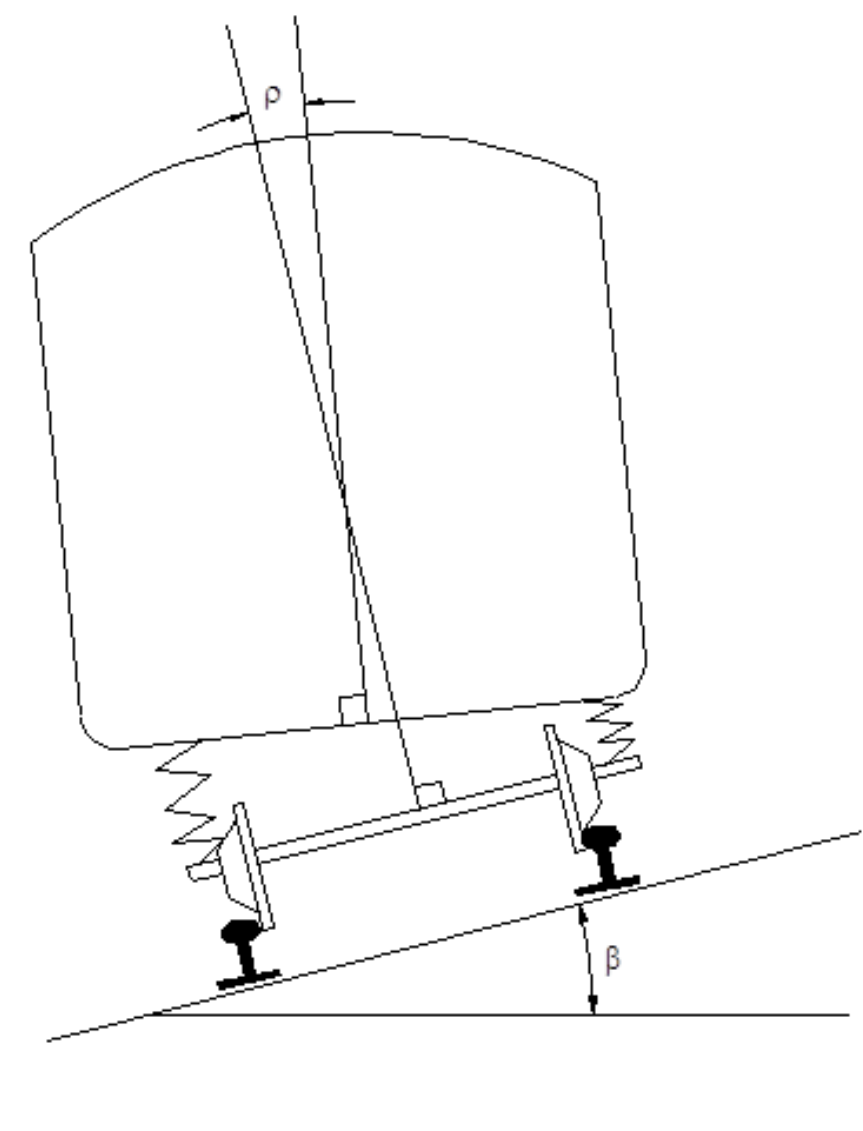
The roll centre is a kinematic property of the suspension arrangement, not necessarily the centre of gravity. Its height \(h_c\) changes the lever arm to a checked body point: the same roll angle produces a larger lateral displacement farther above that centre. Soft suspension can improve ride comfort while increasing the movement envelope. Flexible roll suspension also affects pantograph sway, so body clearance and current collection must be designed together.
14.7.2 Horizontal Space Required in a Curve: Inside (Centre Throw)
For the inside of a curve, the clearance calculation adds relative wheelset and bogie displacements, roll due to cant effects, and the centre-throw term. Figure 14.33 identifies these components before they are assembled in the space-required calculation below.
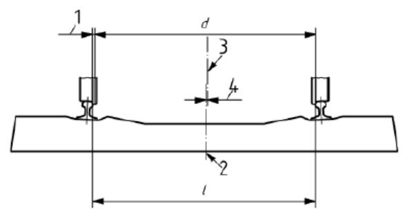
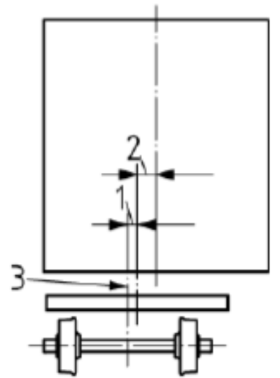
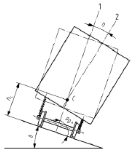
Figure 14.33(a) identifies wheelset-to-rail play, 14.33(b) the additional relative movement between wheelset, bogie and body, and 14.33(c) the effect of cant. Keep these contributions distinct when following their corresponding terms in the space-required calculation.
Wheelset to rail play
Vehicle body to bogie and
bogie to wheelset play
Superelevation in the track
Read Figure 14.33 as three offsets that are added to the vehicle half-width in the formula:
- Wheelset sketch: line 2 is the track centre line and line 3 is the wheelset centre line after the wheelset has shifted toward one rail. The one-sided wheelset play is the difference between the calculation track gauge \(l\) and the wheelset guiding width \(d\), divided by two:
Callout 4 is the horizontal offset between line 2 and line 3; this is the play \(\sigma\). Callout 1 marks the rail-side clearance that limits this shift. The formula therefore adds the term \(A_\sigma\sigma\).
-
Bogie/body sketch: the lateral displacement continues from the wheelset to the vehicle body. Callout 1 gives the bogie-to-wheelset play \(q\), callout 2 gives the car-body-to-bogie play \(w\), and callout 3 marks the wheelset centre. These clearances are added as \(A_q q + A_w w\).
-
Superelevation sketch: line 1 is normal to the track plane and line 2 is the inclined body centre line. The body rotates about roll centre \(C\), at height \(h_c\). Cant deficiency or cant excess creates a small rotation; at the checked height \(h\), the horizontal shift is calculated with the lever arm \((h-h_c)\).
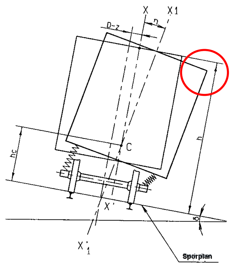
For the cross-section halfway between the bogie pivots on the inside of the curve (vehicle stationary), use the centre-throw geometry \(K_i\) shown earlier in Figure 14.13. The variable \(n_i\) locates the checked cross-section from the nearest bogie pivot toward the vehicle centre, so the curve term below calculates the inward movement at that section. The additional lateral displacement, before adding the actual vehicle half-width, is:
Terms (1), (2), and (3) are, respectively, the relative-displacement allowance, the cant-and-roll allowance, and the curve-overthrow allowance. Here, \(s\) is the dimensionless roll-angle coefficient used in gauging; it is unrelated to the effective track-spacing symbol \(s\) used in Chapter 7.
Use consistent millimetre units in these vehicle-displacement formulas, including the radii. The positive-part notation means \((h-h_c)_{>0}=\max(h-h_c,0)\). The numerical clearances and suspension values below describe the teaching calculation, not universal limits for every vehicle. When using an approved dynamic reference profile instead, follow its associated rules so that movements already included in that profile are not added twice.
where:
-
\(D^{pl}_{i}\) = required lateral space on the inside of the curve, for a cross-section between the bogie pivots (mm)
-
\(A_\sigma = A_q = A_w = 1\) (displacement coefficients, EN 15273)
-
\(\sigma = 27.5\) mm (wheelset-to-rail clearance)
-
\(q = 5\)–\(6\) mm (wheelset-to-bogie clearance)
-
\(w = 60\)–\(65\) mm (car body-to-bogie clearance)
-
\(s = 0.150\)–\(0.225\) (roll angle coefficient)
-
\(D_\text{max} = 150\) mm (maximum cant; 160–180 mm on passenger-only lines)
-
\(D_\text{sup} = 40\) mm (cant supplement due to vertical defects in the track geometry)
-
\(h\) = height of the checked vehicle point above the track plane (mm)
-
\(h_c = 650\)–\(1000\) mm (roll centre height above the track plane)
-
\(R\) = curve radius (mm)
-
\(a\) = bogie pivot distance (mm)
-
\(p\) = axle spacing in the bogie (mm)
-
\(n_i\) = longitudinal distance from the nearest bogie pivot to the checked cross-section, toward the vehicle centre (mm)
The red circle in Figure 14.34 identifies the upper body corner checked for this stationary inside-curve case. The roll-centre height and the distance above it determine how body roll contributes to the lateral displacement.
14.7.3 Horizontal Space Required in a Curve: Outside (End Throw)
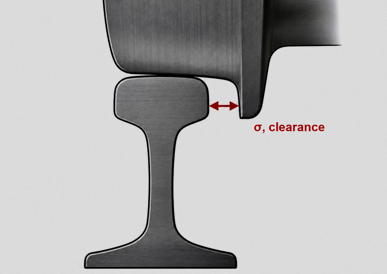
The outside-curve calculation uses the lateral play between wheelset and rails. Norway's nominal track gauge is 1435 mm. The value 1465 mm is the widened calculation gauge used to obtain the maximum lateral play. It is combined with a minimum wheel guiding width of 1410 mm in Bane NOR's rules for track geometry and profiles [19, 55]. The one-sided wheelset-to-rail lateral play is therefore \(\sigma=(1465-1410)/2=27.5\) mm. Figure 14.35 isolates this quantity: the red double-headed arrow marks the one-sided gap between the wheel-flange face and the rail gauge face.
Beyond a bogie pivot on the outside of the curve (vehicle in motion), the wheelset-to-track and wheelset-to-bogie clearances follow the EN 15273 end-section lever factor \((a+2n_a)/a\) [94]. The full standard keeps the two directional bogie-to-body clearances separate. In the simplified symmetric-clearance model used here, \(w_i=w_a=w\), so their two lever-arm contributions combine to the same factor \((a+2n_a)/a\):
Terms (1), (2), and (3) are, respectively, the amplified relative-displacement allowance, the cant-deficiency-and-roll allowance, and the end-throw allowance.
where:
-
\(D^{lp}_{a}\) = required lateral space on the outside of the curve, for a cross-section beyond a bogie pivot (mm)
-
\(\tfrac{a+2n_a}{a}\) = simplified end-section lever factor for relative displacements beyond the bogie pivot
-
\(A_\sigma\), \(A_q\), \(A_w\) = displacement coefficients for wheelset-to-rail, wheelset-to-bogie and bogie-to-car-body movement; the base coefficient is 1, with the symmetric-clearance end-section factor applied by \(\tfrac{a+2n_a}{a}\)
-
\(\sigma = 27.5\) mm (wheelset-to-rail clearance)
-
\(q = 5\)–\(6\) mm (wheelset-to-bogie clearance)
-
\(w = 60\)–\(65\) mm (car-body-to-bogie clearance)
-
\(s = 0.150\)–\(0.225\) (roll angle coefficient)
-
\(I_\text{max} = 80\)–\(245\) mm (maximum cant deficiency, depending on line curvature and rolling stock)
-
\(I_\text{sup} = 60\) mm (cant-deficiency supplement due to vertical defects in the track geometry)
-
\(h\) = height of the checked vehicle point above the track plane (mm)
-
\(h_c = 650\)–\(1000\) mm (roll centre height above the track plane)
-
\(R\) = curve radius (mm)
-
\(a\) = bogie pivot distance (mm)
-
\(n_a\) = longitudinal distance from the nearest bogie pivot to the checked cross-section, toward the vehicle end (mm)
-
\(p\) = axle spacing in the bogie (mm)
The same geometry in Figure 14.13 is used below: \(n_i\) is used for cross-sections between the bogie pivots, while \(n_a\) is used for cross-sections beyond a bogie pivot.
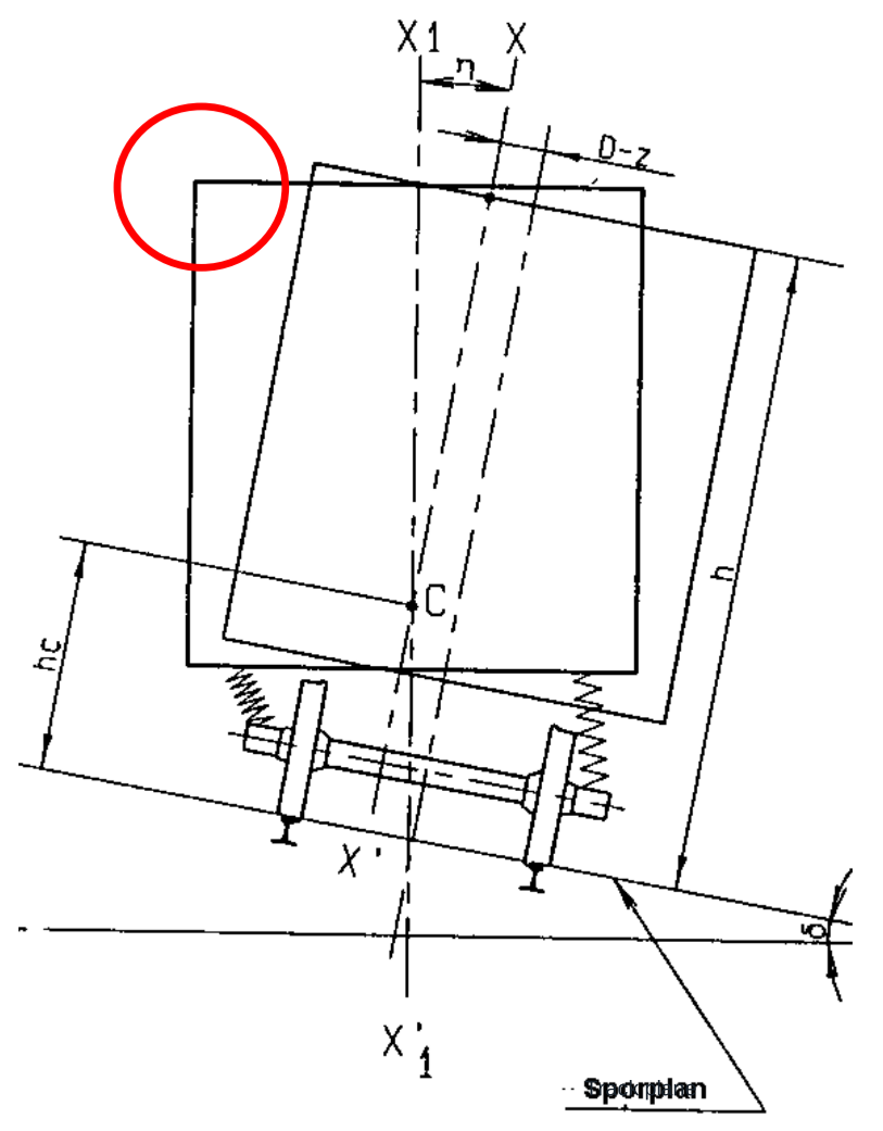
Figure 14.36 marks the upper corner governing the illustrated outside-curve case beyond the bogie pivots. It must be assessed with the outside-case movement assumptions, not copied from the stationary inside case.
14.7.4 Horizontal Space Required on Tangent Track
On tangent track, there is no curve overthrow, but the vehicle still sways due to suspension movements and cant deficiency (from track geometry errors). The formula is similar to the curve case but with the static overthrow term set to zero:
Tangent track does not eliminate suspension movement. Figure 14.37 marks the upper corner in red and a lower body point in orange: both must be considered with their height relative to the roll centre, even though the geometric curve-throw term is absent.
14.7.5 Worked Example: Space Required in a Curve
Example: A B7 passenger wagon is checked in a horizontal curve with \(R = 500\) m. The checked upper corner is at \(h = 3500\) mm above the track plane, the roll centre is \(h_c = 1000\) mm, and the half-width of the vehicle body at the checked height is \(b = 1530\) mm. Use:
For compactness, all length values in the numerical substitutions below are in millimetres; the curve radius is therefore inserted as \(R=500\,\mathrm{m}=500\,000\,\mathrm{mm}\).
Outside of the curve, beyond the bogie pivot, vehicle in motion:
The required horizontal distance from track centre line to this point of the vehicle envelope is therefore:
Inside of the curve, halfway between bogie pivots, vehicle stationary:
The corresponding horizontal distance from track centre line is:
The worked example shows why a route check must specify where on the vehicle the calculation is made. The outside end section is governed by amplified relative displacement, cant-deficiency roll and end throw; the inside mid-body section is governed by centre throw and the cant case.
14.8 Platform Clearances and Universal Design
Platform checks must combine the infrastructure edge, the local track geometry and the actual vehicle/door arrangement. The lecture first examines the geometric edge position, then the resulting boarding gap.
14.8.1 Curves, Partial Curves and Turnouts
Let \(A_0\) be the tangent-track distance from track centre to the platform or loading-ramp edge. With no cant, the circular-curve values are \(A_i=A_0+K_i\) on the inside and \(A_y=A_0+K_y\) on the outside. For the current passenger-platform case \(A_0=1680\) mm; loading ramps have their own base offsets, including the 2240 mm train-track case. Do not carry the platform base value over to every loading installation. Figure 14.38(a) shows the constant-radius case, 14.38(b) shows a platform partly beside a curve, and 14.38(c) shows a turnout beside a platform. [257]
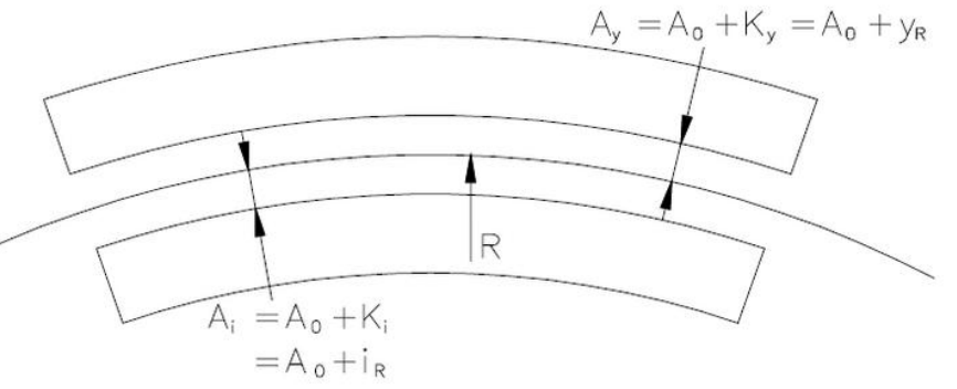
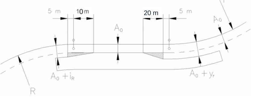
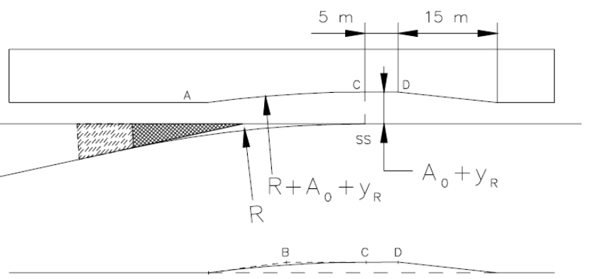
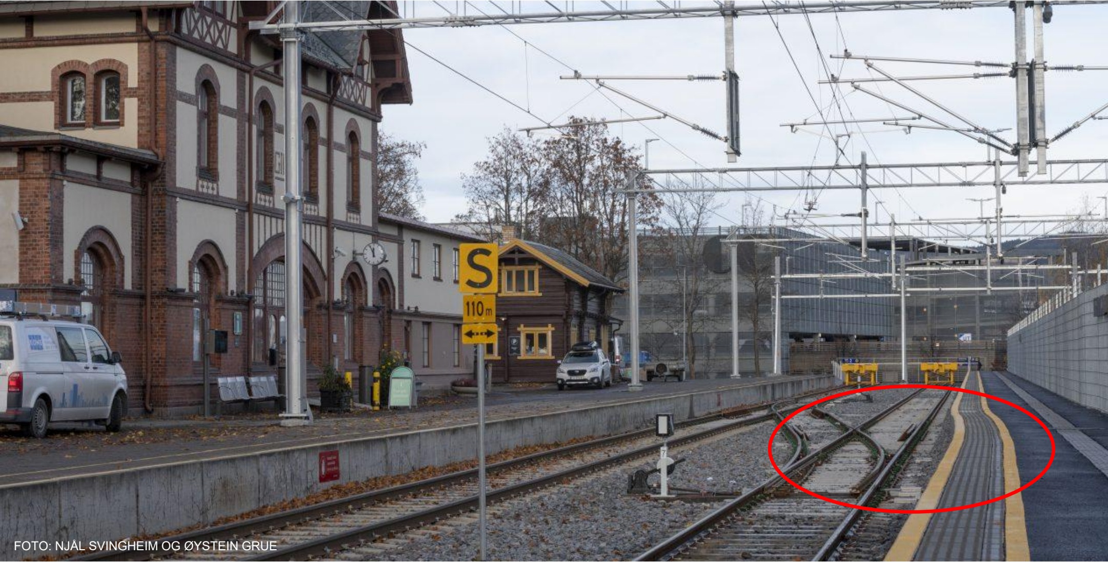
Figure 14.38(d) shows the real arrangement corresponding to the turnout sketch in 14.38(c). The red ellipse highlights the turnout and crossing beside the platform edge. Check the vehicle's swept envelope along each route through this area, not just along the apparently straight platform track. The photograph illustrates the layout; it does not establish that the clearances meet current requirements.
Where curvature changes near a platform end, the required edge offset changes along the platform; it must not jump from zero overthrow to the full circular-curve value. Table 14.7 gives the transition reaches from the current appendix, in the stated direction from larger to smaller curve radius. The outside-curve 20 m label in panel (b) has been updated to match that appendix. At a turnout, include the diverging-route swept envelope, even if the platform-side route appears nearly straight. A straightened A–B–C edge can simplify construction, but must remain outside every governing envelope.
| Case | Minimum offset retained until | Maximum offset established from |
|---|---|---|
| No cant, inside | 10 m before KP | 5 m after KP |
| No cant, outside | 20 m before KP | 5 m before KP |
| Cant ramp, inside | 10 m before OB | OE |
| Cant ramp, outside | 15 m before OB | 5 m before OE |
Here KP is the curve point, OB the beginning of the transition curve and OE its end. SS denotes the stock-rail front joint at a turnout. These are longitudinal reference locations, not extra clearance quantities. In the sketches, \(i_R=K_i\) and \(y_R=K_y\); \(R\) is curve radius. If a vertical curve is present, the corresponding \(K_v\) check is separate.
14.8.2 Canted Track and Cant Ramps
In this subsection \(h\) means track cant, not the vehicle-point height used in Section 14.7. \(H_p\) is the nominal platform height; \(H_i\) and \(H_y\) are vertical heights above the lowest rail on the inside and outside. \(A_i\) and \(A_y\) are horizontal offsets. Figure 14.39(a) defines the cross-section; 14.39(b) shows the longitudinal variation along a cant ramp. For the illustrated platform-edge arrangement, use millimetres throughout:
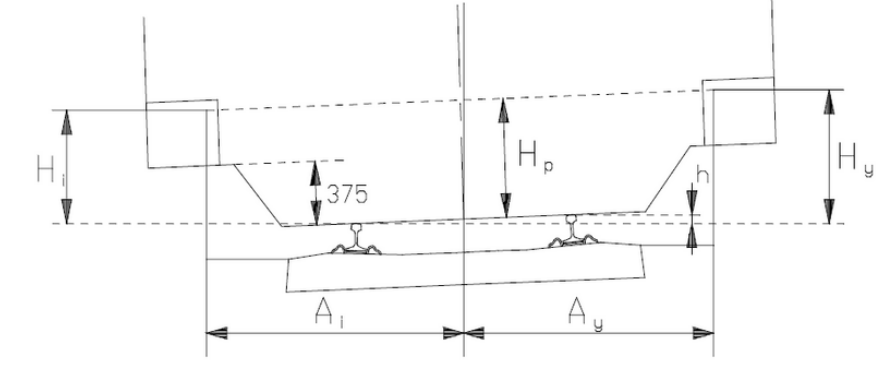
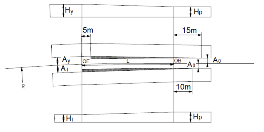
The 375 mm term belongs to the specified platform-edge shape. For the alternative outward-inclined edge meeting the appendix’s angle condition, its outside-offset relation instead uses \(A_y=1680+K_y-hH_p/1500\). Select the correct edge case; do not exchange the two expressions. Along a cant ramp, both offset and height vary; the height transition is linear between OB and OE. These infrastructure relations do not prove that the resulting vehicle–platform gap satisfies boarding-accessibility requirements [257].
Calculation example. With \(R=500\) m, \(h=100\) mm and \(H_p=760\) mm, the reference-vehicle values are \(K_i=81\) mm and \(K_y=63\) mm. Substitution gives \(A_i\approx1811.7\) mm, \(H_i=692.6\) mm, \(A_y=1718.0\) mm and \(H_y=926.2\) mm for the first edge case. These are geometric example results, not issued setting-out dimensions: apply the required rounding, construction tolerances, route conditions and vehicle checks before design approval.
14.8.3 Door Position, Boarding Gaps and Universal Design
Platform clearance is a special gauging problem because the required gap is both a safety clearance and a passenger-accessibility limit. The curved platform in Figure 14.40 illustrates why the door position on the vehicle matters as much as the curve radius.
The vehicle–platform gap in Figure 14.40(a) is the passenger-facing consequence of the curved geometry visible in 14.40(b). Clearance must be checked at the relevant door positions, not inferred from the track centre line alone.
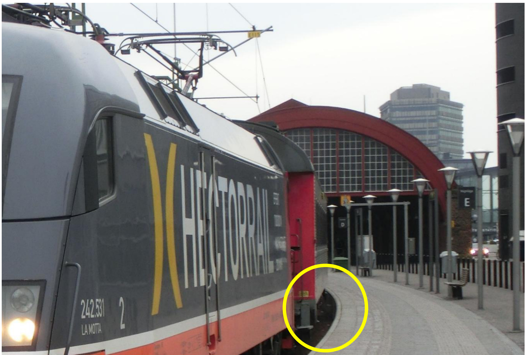
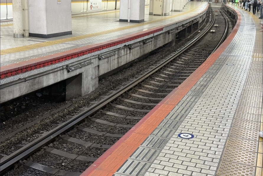
Platform geometry presents the most operationally significant structure-gauge challenge: passengers must step between the platform edge and the vehicle door with a gap that is small enough to be safe and accessible, yet large enough to accommodate the dynamic movements of the vehicle.
For a vehicle in a curve, the centre of the car body shifts inward (centre throw) or outward (end throw) relative to the track centre line. If the platform is on the outside of the curve and the door is near the middle of the car body, centre throw can increase the gap to the platform edge. If the door is near the vehicle end, end throw can instead move the doorway toward an outside platform and reduce the gap. On an inside platform the same centre/end distinction is reversed, so platform checks must use the actual door positions and stopping point rather than a single generic curve correction.
Level access under TSI-PRM. Section 2.3 defines level access by the gap between the platform and the door sill (or an extended bridging plate):
-
Horizontal gap no greater than 75 mm.
-
Vertical gap no greater than 50 mm.
-
No internal step between the door sill and the vestibule.
These conditions define level access; they are not a universal maximum gap for every permitted boarding arrangement. Where level access is not provided, the applicable requirements for boarding aids and assistance must also be considered. See TSI-PRM, Section 2.3 and the boarding-aid provisions [215].
For FLIRT units such as Bm 74/75, boarding gaps must be checked using the actual door positions, deployed footstep, platform height and offset, cant and stopping position. A vehicle-specific radius example cannot establish a universal accessibility limit. Bane NOR’s platform rules, TRV:03955 and TRV:03959–03960 [216], require the train–platform gap to be assessed for the intended rolling stock. They specify a minimum radius of 2000 m for new platforms and at least 300 m for the track alongside a new platform extension or a platform-height increase. These infrastructure requirements and the TSI-PRM level-access definition are separate checks.
The movable footstep on FLIRT Bm 74/75 illustrates a mitigation, not a universal geometry solution. The lecture’s outside-platform example associates a 700 m radius with its particular vehicle and footstep assumptions; this must not replace Bane NOR’s general platform-radius requirements. Warning signs, supervision or edge safety devices address operational risk but do not make an excessive gap into level access. Check where each door actually stops, including the inside/outside-curve reversal.
Figure 14.41 separates the boarding distance at a doorway from the clearance elsewhere along the body. The same vehicle chord gives different gaps at its middle and ends and on the two sides of a curve. This is why the actual doorway, rather than the widest gap in the sketch, is the accessibility check location.
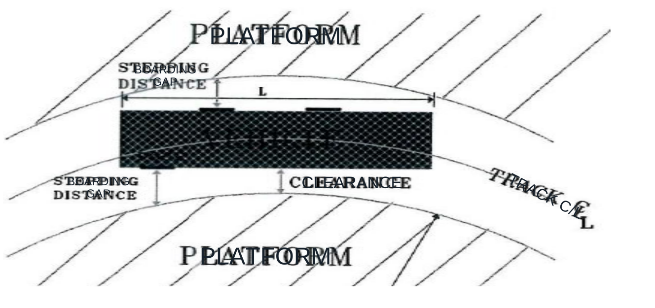
Figure 14.42(a) and 14.42(b) show the FLIRT step arrangements for the illustrated 570 mm and 760 mm platform heights. The photographs in 14.42(c) and 14.42(d) contrast the open gap with a deployed step. A step can bridge part of the gap, but its reach and the remaining horizontal and vertical gaps still have to be checked for the actual stopping position.
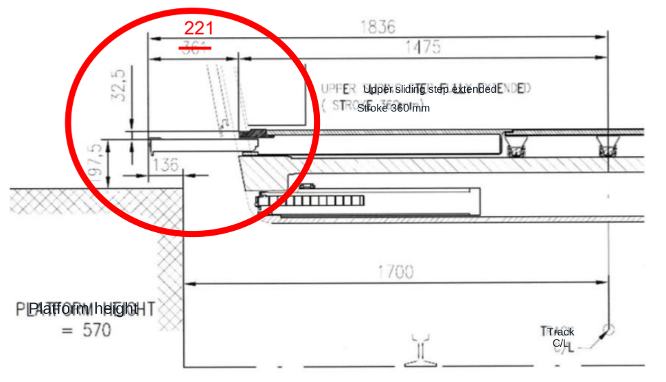
(a) 570 mm platform
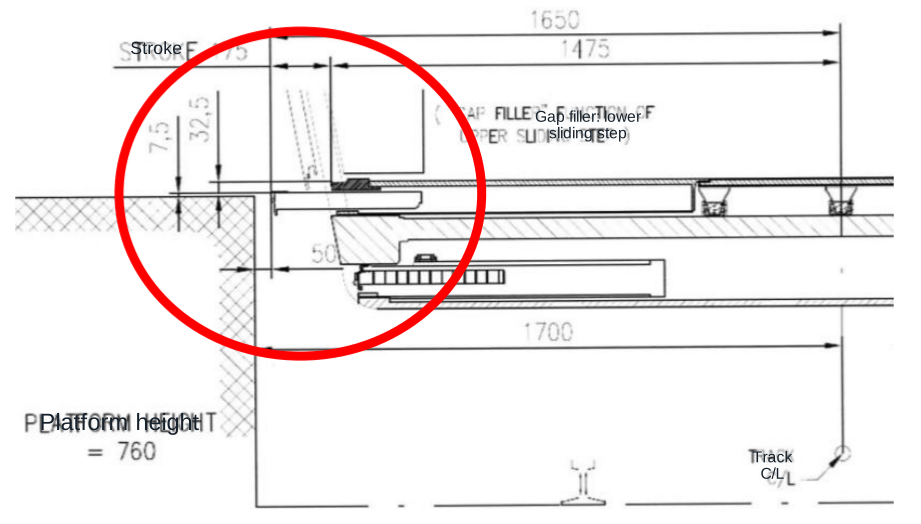
(b) 760 mm platform
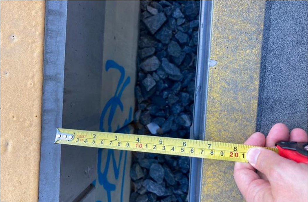
(c) Gap without a deployed step
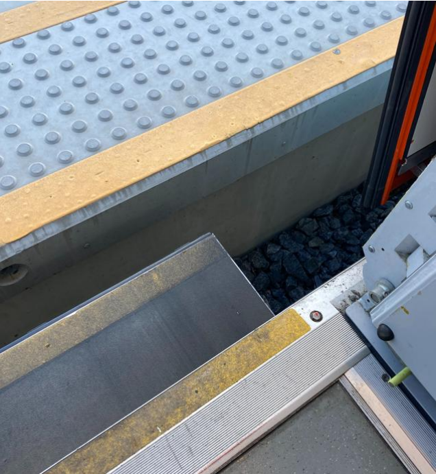
(d) Deployed step
14.9 Vertical Space Required
Vertical space requirements arise from:
-
Vertical curve overthrow (hump or sag geometries).
-
Spring deflection of primary and secondary suspensions.
-
Wheel-diameter differences due to wear.
-
Eccentric loading causing the body to pitch or sink.
-
Unequal wheel wear, body deformation and rolling, with different effects at the lower and upper corners.
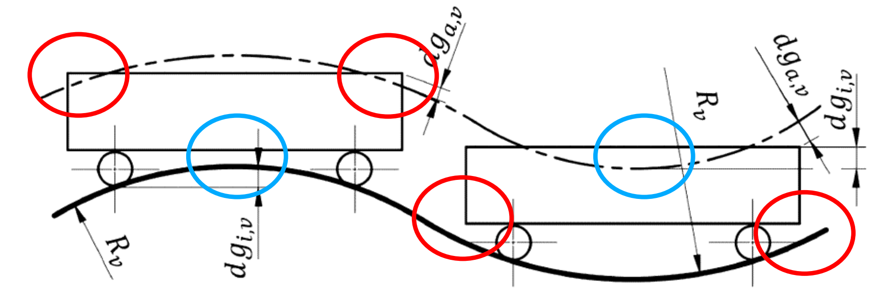
Vertical-curve overthrow is easiest to read by separating the two lower-clearance checks before the formulas. In a concave (sag) vertical curve, the checked lower point can be near the vehicle end beyond the nearest bogie pivot. In a convex (hump) vertical curve, the checked lower point is usually between the bogie pivots, where the vehicle body bridges over the crest. Figure 14.44 compares these two cases visually. The red circle in panel (a) marks the lower end check in the sag; the blue circle in panel (b) marks the lower centre check over the hump. The formulas below name these allowances \(e_a\) and \(e_i\). The other circles identify the upper-clearance cases discussed afterwards.
Figure 14.43 brings the upper and lower checks together. At a crest (left), the upper body ends and the lower middle section are critical; in a sag (right), the upper middle section and lower ends are critical. The red and blue circles distinguish the end and middle checks, not permitted and forbidden positions.
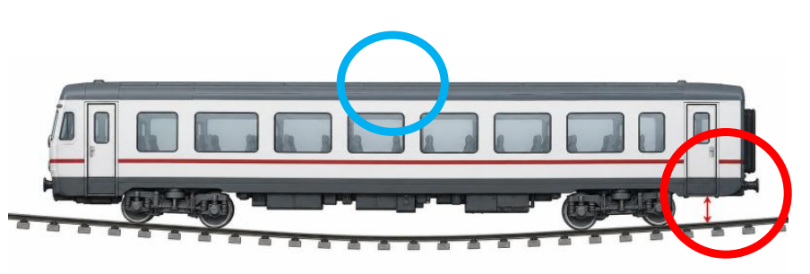
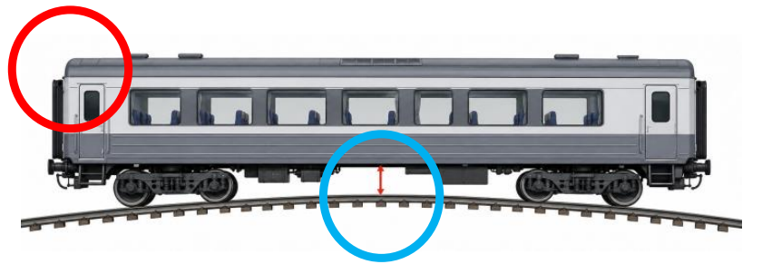
For the sag end case in Figure 14.44(a), the required lower allowance is:
Terms (1), (2), and (3) are the relative vertical displacement, the roll allowance, and the vertical-curve overthrow, respectively.
where:
-
\(e_a\) = required vertical allowance for the lower part of the vehicle, at a cross-section beyond a bogie pivot
-
\(\Delta r_w\) = vertical allowance for reduction in wheel radius due to wear; a specified diameter reduction \(\Delta d_w\) gives \(\Delta r_w=\Delta d_w/2\)
-
\(\Delta h_1\) = primary-suspension deflection
-
\(\Delta h_2\) = secondary-suspension deflection
-
\(f\) = spring deflection due to unfavourable loading
-
\(s = 0.150\)–\(0.225\) (roll angle coefficient)
-
\(I_\text{max} = 80\)–\(245\) mm (maximum cant deficiency, depending on line curvature and rolling stock)
-
\(b\) = distance from the side of the vehicle body to the vehicle centre line
-
\(b_2\) = distance from the secondary suspension to the vehicle centre line
-
\(R_v\) = vertical-curve radius
-
\(a\) = bogie pivot distance
-
\(n_a\) = longitudinal distance from the nearest bogie pivot to the checked cross-section, toward the vehicle end
-
\(p\) = axle spacing in the bogie
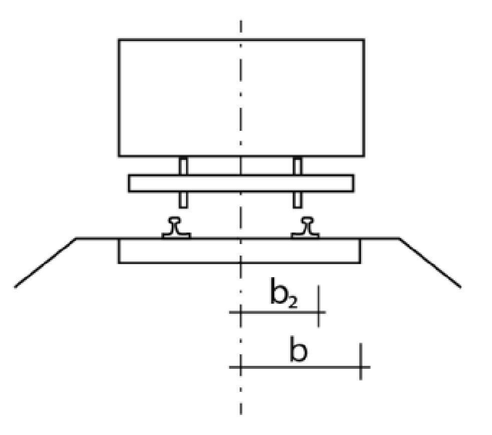
Figure 14.45 shows both transverse dimensions from the same vehicle centre line: \(b\) reaches the body side, while \(b_2\) reaches the secondary-suspension support. Thus \(b_2\) is half the lateral spacing between the two symmetric supports, not their full spacing. The roll term uses only the positive excess, \((b-b_2)_{>0}=\max(b-b_2,0)\).
For the hump centre case in Figure 14.44(b), the same vertical movement allowances are used, but the vertical curve-overthrow term is based on the distance from the bogie pivot toward the middle of the vehicle:
where \(e_i\) is the required vertical allowance at a lower point between the bogie pivots, and \(n_i\) is the longitudinal distance from the nearest bogie pivot to the checked cross-section. For the centre of the vehicle, \(n_i = a/2\).
Upper clearance is a separate check. The controlling locations are reversed: the upper centre section rises relative to a sag curve, while an upper end section rises relative to a hump curve. In the same simplified model, define the roll contribution \(e_{\mathrm{roll}}=s\,I_\text{max}(b-b_2)_{>0}/1500\). The upward geometric and roll allowances are then:
Use the first expression for the sag centre case and the second for the hump end case, with all lengths in millimetres. The downward wear and suspension terms in the lower-clearance calculation are not automatically upward allowances. A complete upper-envelope assessment must additionally consider the vehicle's specified upward suspension travel, tolerances and operating conditions.
14.9.1 Clearance Assessment before Procurement
The lecture’s procurement examples make the timing important: establish vehicle–route compatibility before committing to a vehicle design or order. A train that clears the principal tunnel can still fail at a platform, a local sign, a neighbouring train or the contact line. Late discovery can require expensive infrastructure alterations, route restrictions, loading limits or vehicle changes. Specify the intended routes and diversions, survey datum, vehicle/load configuration, suspension and wear cases, speeds and operating conditions, then document the acceptance basis and responsibility for each clearance margin.
14.10 Structure Gauge Control Methods
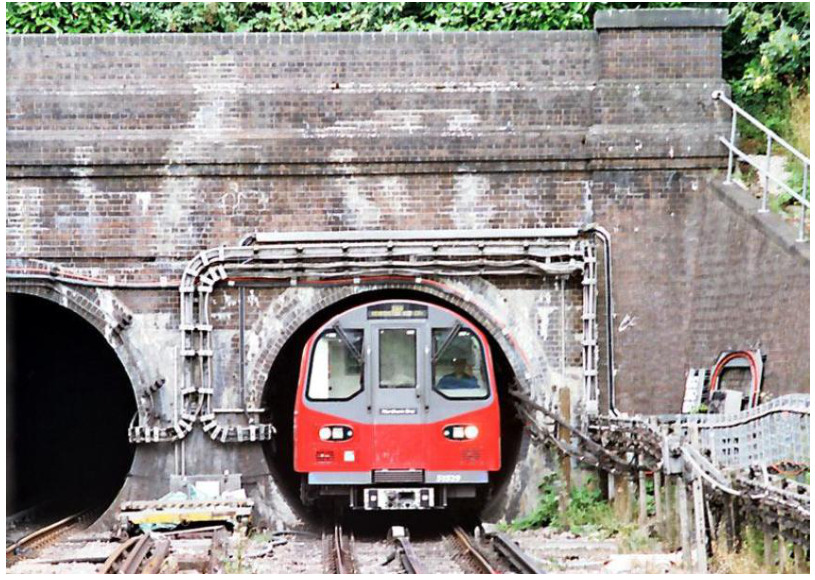
Structure-gauge control combines fixed physical checks with route-wide scanning and simulation. Permanent templates are used in two slightly different ways. At a known clearance restriction, such as a tunnel portal, the template confirms that the local infrastructure clearance is still protected. At loading sites, a loading-gauge frame is a practical go/no-go check before dispatch. Figures 14.46 and 14.47 show the two situations separately.
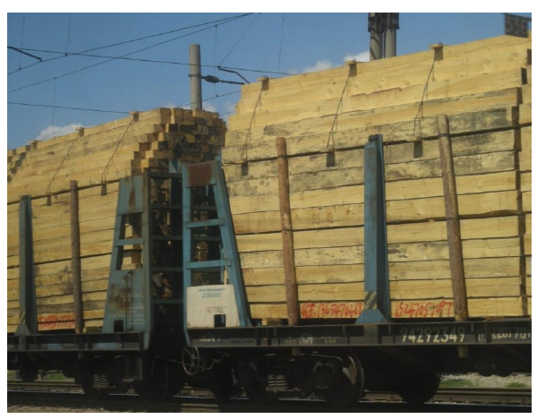
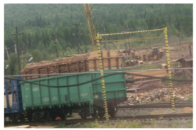
The freight-site frames in Figure 14.47(a), the loaded timber in 14.47(b) and the timber-loading frame in 14.47(c) connect the permitted profile to practical loading checks. Passing a loading frame verifies that local check, not every clearance along the intended route.
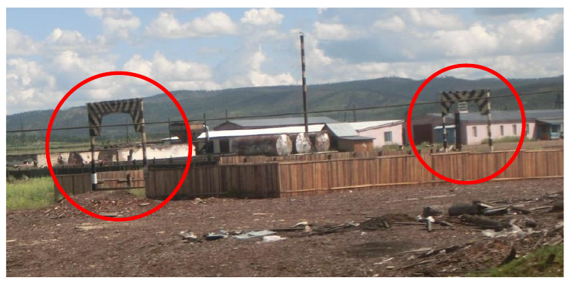
the permitted profile
Four methods are used to verify and maintain structure gauge clearance:
- Permanent templates
-
Physical gauge frames mounted at fixed locations (tunnel portals, under bridges, loading areas and timber terminals) to check that vehicles and loads remain inside the permitted profile. Simple and reliable, but only valid at the template location.
- Laser scanning
-
A rotating laser on a road-rail vehicle or measuring car records the surrounding infrastructure relative to the surveyed track. Point rate, range and measurement uncertainty depend on the instrument and survey method. Check calibration, track reference, coverage and uncertainty before treating a measured near-clearance as acceptable; one instrument's quoted precision is not a general acceptance tolerance.
- Sector Profile Scanner (SPS) / measuring gateway
-
A fixed installation through which trains pass in revenue service, enabling continuous loading-gauge monitoring without a special measuring run. This is useful for loads that can protrude after loading or during transport, such as timber.
- Simulation software (e.g. ClearLoad)
-
Computes the kinematic envelope [68] of new vehicle types on specific lines, used for:
-
Acceptance of new rolling stock.
-
Planning structure gauge enlargements.
-
Special transport authorisation.
-
Cross-section E (pantograph) verification [51].
-
Laser scanning extends the same clearance principle from one fixed location to the whole route. Figure 14.48 shows a structure-gauge control vehicle used for clearance scanning.
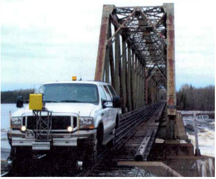
The lecture’s scanner example quotes up to 40 000 points/s, an approximately ±4 mm instrument figure and a measuring range up to 70 m, with day/night operation. These describe that example system, not a guaranteed route-survey uncertainty or acceptance tolerance. The rotating scanner produces cross-sectional coordinates relative to the measured track; calibrating the sensor, locating the rail reference and covering obscured surfaces remain essential. Vehicle-mounted equipment and a PC display are only parts of that measurement chain.
The rotating-laser illustration in Figure 14.49(a) shows successive measured cross-sections. The historical output in 14.49(b) shows how a plotted section and a load outline can be compared. Keep the location and measurement assumptions with the plot; a screen image alone does not establish clearance. The original software display and its L-KOPIA/LKO credit are retained.
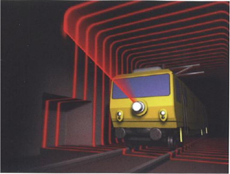
(a) Rotating-laser principle
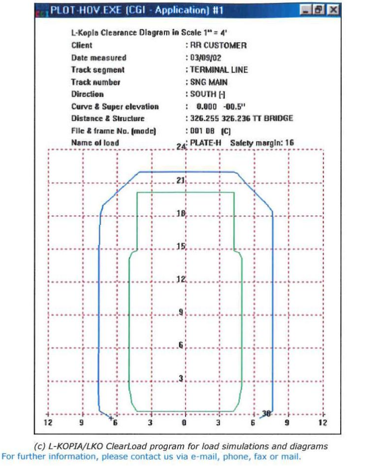
(b) Clearance output, L-KOPIA/LKO
A measuring gateway is the fixed-installation equivalent for loading-gauge control in operation. Instead of sending out a dedicated measuring vehicle, the train passes between scanners that compare the actual vehicle and load outline with the permitted profile. Figure 14.50 illustrates this principle for a timber load, where a single protruding log can govern whether the wagon is inside the allowed loading gauge.
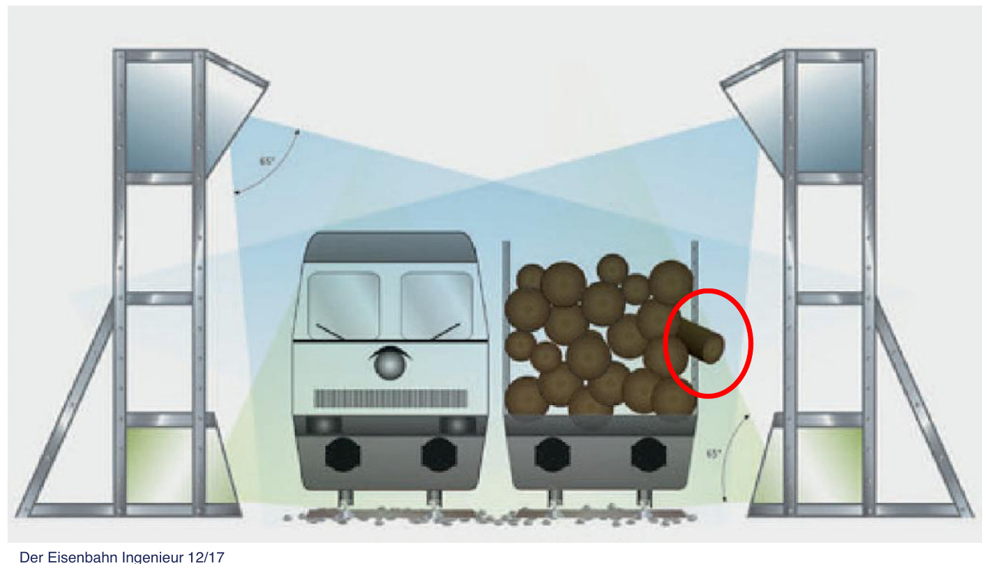
An en-route laser-beam/loading check detects the passing load, whereas a route survey measures the infrastructure. The two measurements answer different questions and neither replaces the other. In ClearLoad or equivalent simulation output, trace every reported restriction back to the location, surveyed cross-section, track position and assumed vehicle/load movement envelope. Record the minimum clearance or exceedance and the governing case, not only a coloured pass/fail outline. Such results support new-stock assessment, enlargement planning, exceptional consignments and pantograph checks; software output is not independent route authorisation.
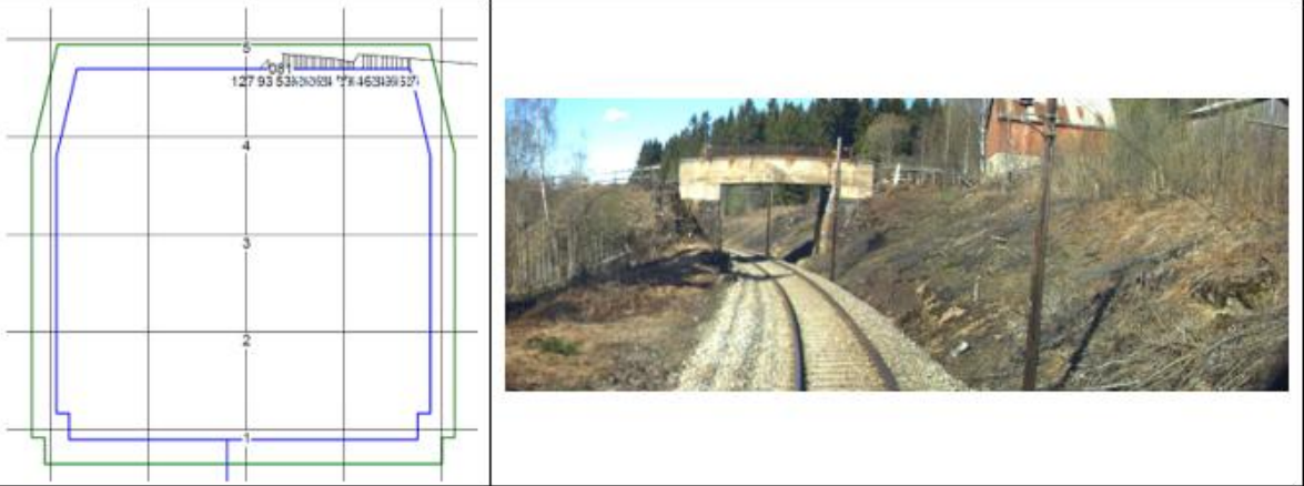
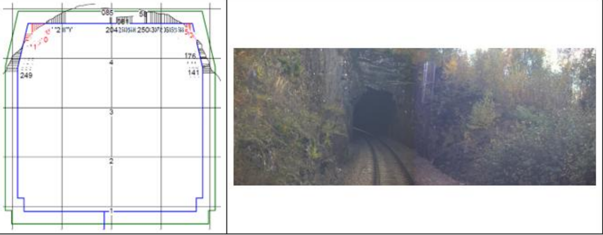
Figure 14.51(a) pairs a bridge clearance plot with the corresponding location photograph; 14.51(b) does the same for a tunnel. Read the section, the relevant obstruction and its location together. These are historical examples of the assessment workflow, not current route approvals.
(a) Bridge
(b) Tunnel
14.11 Constraints and Enlargements
Many locations on the Norwegian network have known structure-gauge constraints, particularly in older tunnels and rock cuttings where the cross-section was cut to the minimum required for the gauge standards prevailing at the time of construction. These constraints prevent the operation of modern rolling stock types (e.g. wider freight wagons, bi-level coaches, semi-trailer wagons) on affected sections.
Enlargement options include:
-
Tunnel re-profiling (rock blasting or grinding).
-
Lowering the track formation.
-
Replacing a conventional overhead line with a rigid overhead conductor rail where suitable, reducing the overhead installation's construction height. The pantograph's movement envelope and electrical clearances must still be satisfied.
-
Re-routing (new alignment in the affected section).
New protective structures (snow sheds, rockfall covers) are constructed to the current standard gauge from the outset.
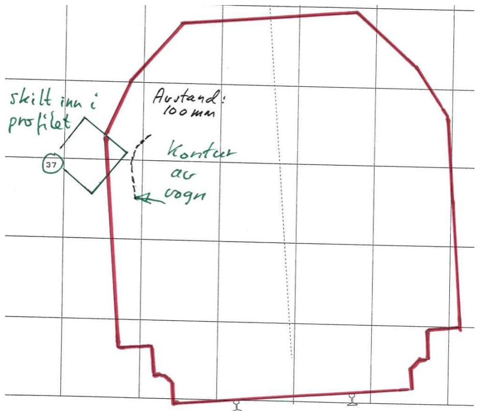
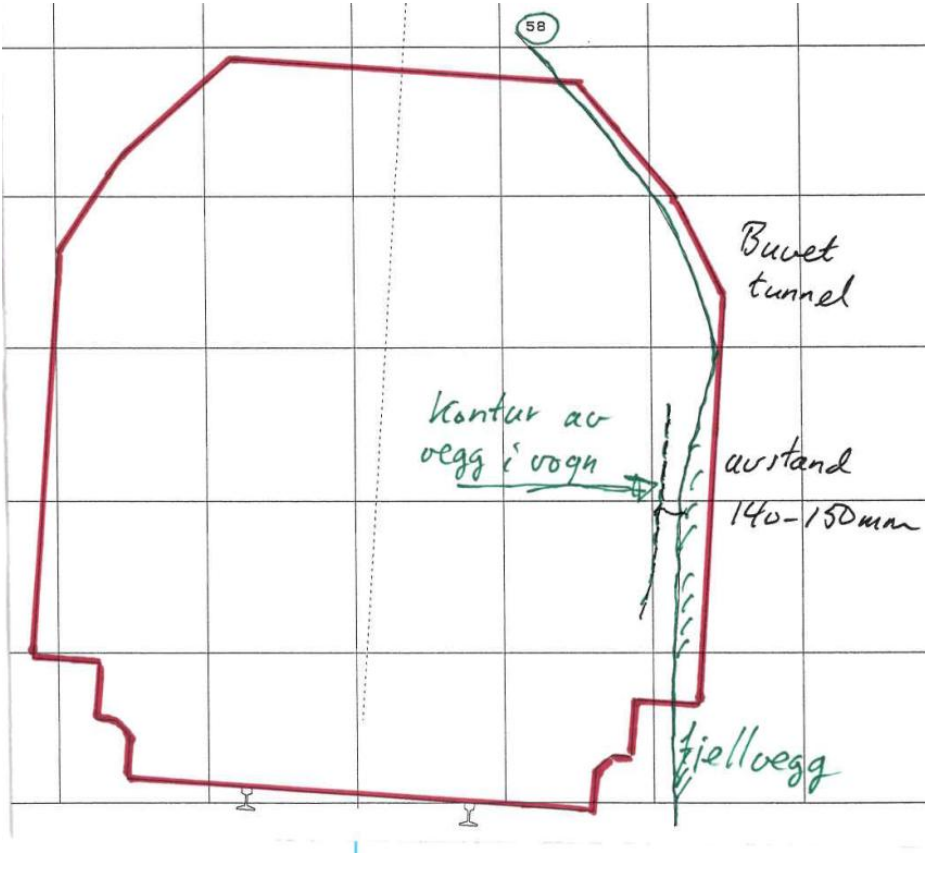
The original survey sketches in Figure 14.52(a) and 14.52(b) locate a projecting sign and a rock/tunnel wall relative to the profile. Their handwritten Norwegian annotations are retained as part of the measurement record: “skilt inn i profilet” means a sign intruding into the gauge, “kontur av vogn” the vehicle outline, “avstand” distance, and “fjellvegg” the rock wall. The noted 100 mm and 140–150 mm are local survey dimensions, not general design clearances.
(a) Projecting sign
(b) Rock/tunnel wall
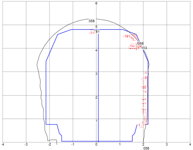
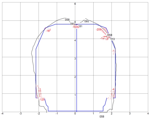
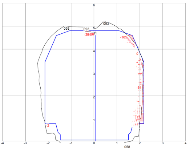
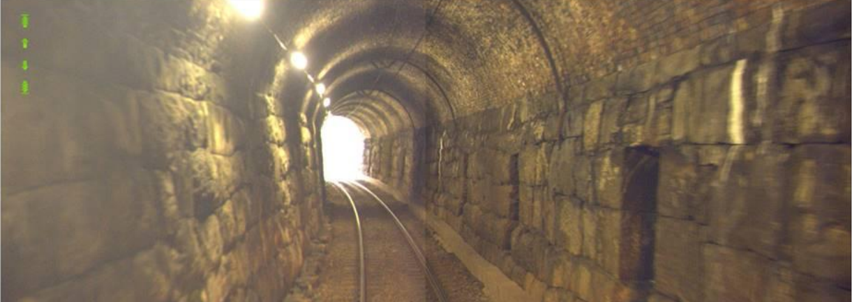
The historical Nidareid tunnel example in Figure 14.53 illustrates how an older tunnel can govern a route. It is an example of a geometric constraint, not a statement of current transport approval through that location.
The three sections in 14.53(a), 14.53(b) and 14.53(c) show that the governing clearance varies along the same tunnel. The photograph in 14.53(d) gives the physical context; it cannot replace the measured profile comparisons.
(a) Measured section 1
(b) Measured section 2
(c) Measured section 3
(d) Tunnel photograph
A sign projecting inside the protected outline and a tunnel-wall intrusion are different physical causes of the same clearance failure. The Nidareid example also illustrates why the available space must be compared with the correct vehicle/profile case and measured track position, rather than with the tunnel opening in isolation. After track works or installation changes, reassess the affected section: the previous surveyed clearance may no longer apply.
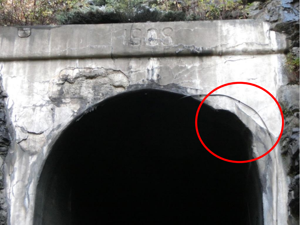
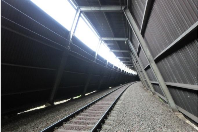
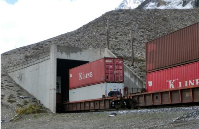
Figure 14.54(a) shows local tunnel-profile enlargement. The snow shed in 14.54(b) and rockfall cover in 14.54(c) illustrate protective structures that must also maintain the required gauge. Profile work must be coordinated with structural safety, electrification and the track position.
14.12 Chapter Summary
Clearance envelope. The gauge is the boundary inside which fixed infrastructure must not intrude. It must account for the static vehicle outline, suspension movement, track tolerances, wheelset play, cant, curve overthrow, construction deviations and maintenance allowances. Gauge design is therefore a clearance problem between vehicle behaviour and infrastructure position.
Gauge profiles. The static profile describes the vehicle at rest, while kinematic and dynamic profiles include movements caused by suspension, curvature, speed and track geometry. A structure that clears a static vehicle may still be unsafe for a moving train. The choice of profile therefore depends on whether the engineer is checking rolling stock, route compatibility, new infrastructure or an existing constrained site.
Curve effects. On curved track, the middle and ends of a vehicle do not follow the same path as the bogie centres. Centre throw and end throw increase the horizontal space required inside and outside the curve, and the effect depends on vehicle length, bogie spacing and curve radius. Transition curves and vertical curves add further variations, so gauge checking must use the local track geometry rather than a single constant clearance.
Platforms and centres. Passenger platforms must be close enough for safe boarding but far enough from the swept envelope of passing trains. Track centre distance must allow two trains to pass with adequate clearance, including dynamic effects and maintenance tolerances. These requirements become more demanding in curves, at high speeds and where existing infrastructure limits the available space.
Gauge control. New lines can meet current gauge requirements from the outset, but existing lines often contain older tunnels, bridges, platforms or rock cuttings with limited clearance. Laser scanning, gauge-control vehicles and route classification help identify where rolling stock is compatible, and where infrastructure modification or operational restriction is required.
Assignments
Assignment 1: Gauge concepts
Before doing calculations, explain the basic gauging terms in words.
(a) Explain the difference between the static loading gauge, the kinematic gauge and the dynamic gauge.
(b) Explain the difference between a vehicle or loading profile and a structure gauge.
(c) Explain why a route check must specify the vehicle point, curve side, operating condition and gauge profile being checked.
Assignment 2: B7 passenger wagon horizontal space requirement
Between 1980 and 1990, NSB purchased the B7 passenger wagons, which are now mainly used on the Bergen line and the Sørland line after refurbishment. Use the following simplified vehicle data:
Use millimetres for every length inserted in the formulas below; \(s\) is dimensionless.
Use the one-sided wheelset-to-rail lateral play \(\sigma=27.5\) mm and the simplified displacement coefficients \(A_\sigma=A_q=A_w=1\). All dimensions to the end of the car body include buffers. The car-body side is slightly arched, but for this assignment check the same half-width at two heights:
The available half-width in the dynamic gauge NO1 at \(h = 3500\) mm is \(B_1 = 1700\) mm. For the structure gauge A-85 at the same height, use the curved-track half-widths \(B_2 = 2175\) mm for the outside/end check and \(B_2 = 2201\) mm for the inside/mid-body check. These A-85 values are obtained by interpolating the tangent A-85 half-width at \(h=3500\) mm and adding the appropriate curve-overthrow widening.
(a) Decide the required space at the upper corner at the end of the car body on the outside of a curve with radius \(R = 350\) m when the car is in motion. Use \(I_\text{max}=160\) mm and \(I_\text{sup}=60\) mm. Check the result against NO1 and A-85.
(b) Decide the required space at the upper corner halfway between the bogies on the inside of the same curve when the wagon is at rest. Use \(D_\text{max}=150\) mm, \(D_\text{sup}=40\) mm and \(n_i=a/2\). Check the result against NO1 and A-85.
(c) A platform is located on the inside of the curve. The available distance from track centre line to the platform edge is 1796 mm, and all trains stop at the platform so the cant term may be taken as zero. Is this distance sufficient for the lower corner halfway between the bogies?
(d) The door edge to be checked is at the lower-corner height \(h_1=500\) mm and is 500 mm inboard from the car-body end, so \(n_{a,\text{door}}=3950-500=3450\) mm. For this door check, ignore relative displacement and cant terms. Calculate the distance from the door to the platform edge and state whether the door moves toward or away from an inside platform.
Assignment 3: Well car vertical space requirement and reference point
Freight operators use well cars to transport road trailers on a low floor between the bogies. The lowest point of the car is 270 mm above top of rail on tangent track. Check the clearance at the centre of the car in a convex vertical curve with \(R_v = 1500\) m.
Use millimetres for every length inserted in the formulas below; \(s\) is dimensionless.
Figure 14.55 identifies the low-floor region between the bogies used in this assignment. Use the stated dimensions for the calculation rather than scaling distances from the photograph.
Use:
(a) Calculate the required vertical allowance \(e_i\) and the remaining clearance to the top of rail at the centre of the well car.
(b) List reasons for dynamic movements of rolling stock and briefly explain how they affect structure-gauge checks.
(c) Explain what a reference point is. How is the track distance at this point calculated?