Signal and Interlocking System
In this chapter
13.1 Introduction
The signalling system is the nervous system of the railway. Its primary purpose is to prevent train collisions and derailments while simultaneously maximising line capacity [10, 68]. This chapter covers the main components of a railway signalling system: interlocking, train detection, level-crossing protection, automatic train control (ATC) [10] and the transition to the modern European Rail Traffic Management System (ERTMS) [30].
Conventional signalling gives the driver information through lineside signals. ERTMS Level 2 gives movement authority and supervised speed information in the cab, with fixed marker boards identifying locations along the track. Both arrangements still need interlocking, train detection and controlled points. The change concerns how these functions communicate and how the driver receives and follows the authority.
Railway operation involves heavy vehicles with long braking distances. At high speed, the braking distance can extend beyond the driver's view around a curve, through a tunnel or over a crest. Signalling therefore has to secure the route ahead before the train reaches it. It protects against collisions and derailments, while allowing trains to follow and cross each other efficiently. Reliable signalling also reduces the operating cost of controlling traffic.
The signalling system has two related objectives:
-
Safety: prevent conflicting movement authorities and prove the conditions needed for the authorised movement. Shunting and other special operating cases require their own rules and protections.
-
Efficiency: release infrastructure for the next movement once the train has cleared it and the required release conditions have been fulfilled.
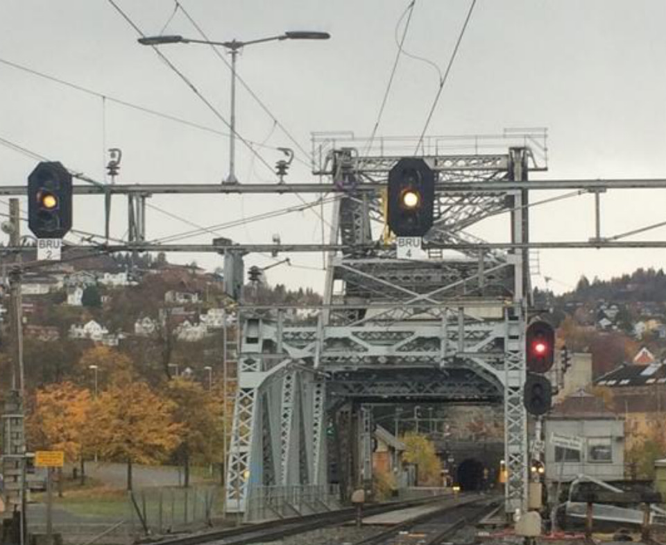
Figure 13.1 shows example lineside signals at Skansen bridge in Trondheim. The photograph is used here as a visual example of installed signalling equipment, not as a complete signalling-layout drawing.
The chapter follows route logic and traffic management through fail-safe operation, level crossings, train detection, points and line block, to national ATC, ERTMS and simultaneous entry. The signalling functions include:
-
Interlocking: ensures that conflicting routes are never set simultaneously.
-
Line block: prevents incompatible permissions to enter the sections between stations.
-
Level-crossing system: controls road crossings.
-
Centralised Traffic Control (CTC): provides remote supervision and control of the network.
-
Automatic Train Control (ATC): enforces supervised speed and signal information on-board.
-
Additional subsystems: shunting yard control, avalanche detection, tunnel gates, moveable bridge interlocking.
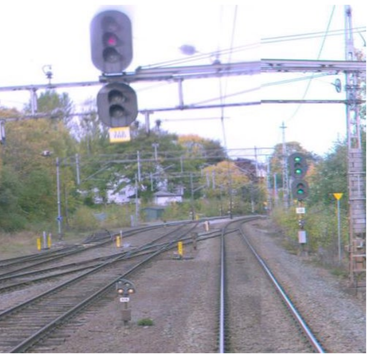
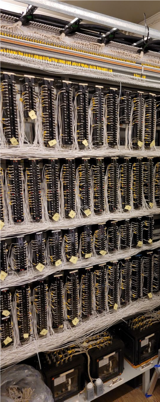
These functions have an external part, visible beside or within the track, and an internal part, containing the logic and interfaces that control them. Figure 13.2(a) shows the external objects beside the track, including signals. The relay racks in Figure 13.2(b) belong to the internal equipment implementing the dependencies between these objects. The photographs show why a signalling installation must be understood as a complete system rather than as a collection of signal heads.
13.2 Interlocking
Interlocking is the safety layer that turns signalling rules into enforceable route logic. It prevents incompatible movements from being authorised at the same time.
13.2.1 Concept
The interlocking is the core safety logic of the signalling system. It is a state machine that enforces dependencies and locking rules between signals, points (switches), and track sections. A train route is a defined part of track between a starting point and an ending point, which may be signals or ERTMS marker boards.
Bane NOR distinguishes a secured route, which excludes conflicting authorities, from an established route, for which all conditions for the intended fully supervised movement have been proved. The route-setting checks below describe normal establishment, not every degraded operating mode. See the interlocking definitions [245].
To set a train route, the interlocking must verify that:
-
All track sections within the route are free.
-
All signals conflicting with the route are set to "Stop".
-
The safety zone beyond the end of the route is unoccupied.
-
All points within and immediately beyond the route are correctly positioned and locked.
Only once all conditions for normal movement are satisfied may the entry signal display a proceed aspect. Route release depends on the train's passage and the designed release sequence. Some installations use a time delay as part of that sequence.
13.2.2 Technology Generations
Interlocking technology has evolved through three generations:
Mechanical interlocking (pre-1950s).
Levers, rods and cams physically enforced the dependencies. Changing a signal or point position without satisfying prerequisites was mechanically impossible.
Relay-based interlocking (1950s–present).
Electromagnetic relays implement the logic in relay circuits. Norwegian relay systems include NSI-63, NSB-77, NSB-78, NSB-84 and NSB-87 [43]. A normally energised safety circuit can withdraw a permissive output when its relay coil loses power. This is one design principle, not proof that every relay failure is safe: contact faults, wiring faults and combinations of failures must be covered by the circuit design, verification and safety case. Bane NOR requires a demonstrated safe state following a fault [210].
Electronic interlocking (1990s–present).
Software logic replaces relay ladders. Norwegian examples include NSB-94/Merkur, Ebilock 850, Ebilock 950, Siemens Simis-C and Thales L90-5 [28]. Computer interlocking offers flexibility and remote diagnostics but requires rigorous formal verification to achieve the same safety integrity as relay systems.
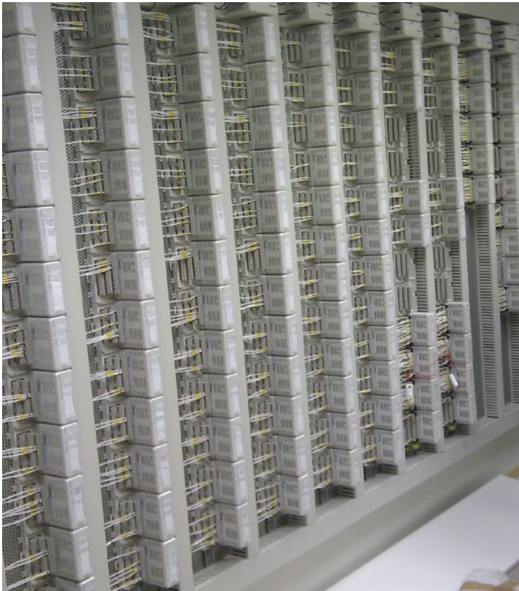
The safety logic may be implemented in very different hardware. Relay interlockings realise the route logic with hard-wired contacts and coils; a normally energised safety circuit can withdraw permission when its relay loses power, provided the complete circuit is designed and verified for that safe response. Electronic interlockings implement the same logic in safety-certified processors connected to signals, points and track circuits through input/output modules. They are more compact and easier to interface with CTC and ERTMS, while relay rooms are physically larger and later changes often require rewiring.
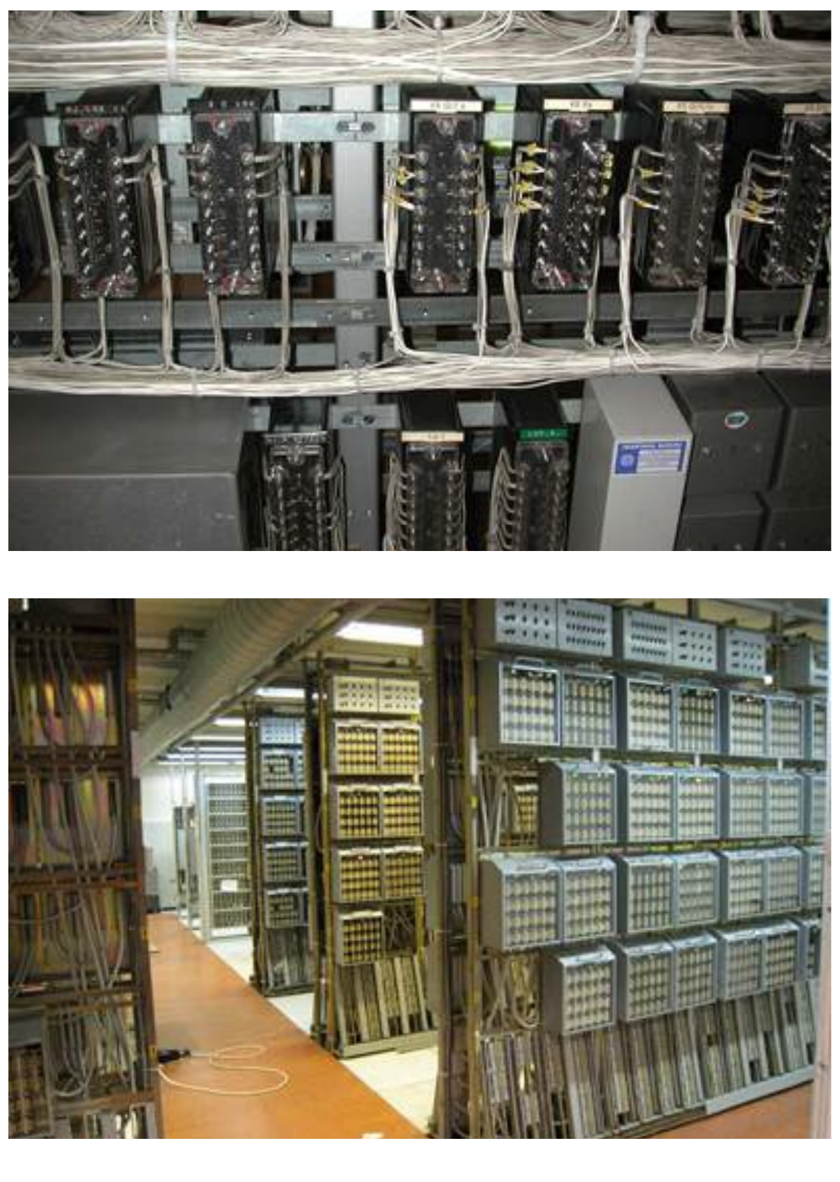
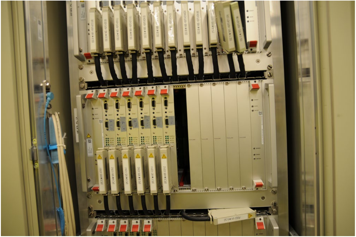
Figure 13.3(a) shows equipment racks in an electronic interlocking installation: software-based route logic still needs physical wiring and interfaces to the trackside equipment. Figure 13.3(b) shows individual relays and a wider view of a relay room, illustrating the extensive wiring used to realise the logic with contacts and coils. The plug-in electronic modules in Figure 13.3(c) show a different equipment arrangement. Hardware modules can be replaced for maintenance, but changes to the safety logic still require controlled verification.
Example: setting an entry route
The layout in Figure 13.4 follows an entry from main signal B to track II. Read it as a sequence of requests, checks and locking, rather than as a command sent straight from the dispatcher to the signal.

- The dispatcher requests the route from B to track II.
- The interlocking checks the detection sections and the positions of the objects belonging to the route.
- It checks the conflicting signals and excludes incompatible routes.
- It checks the protection beyond the route end, including the required safety zone.
- It locks the necessary objects and dependencies. Once all conditions are proved, it permits the appropriate proceed aspect.
- After the train has entered and cleared the relevant sections, the designed release sequence removes the route locking. A release delay may form part of that sequence.
The dispatcher requests the movement. The interlocking determines whether the request can be safely authorised.
13.2.3 Optical Signals
Optical lineside signals in Norway are aspect-based: the meaning depends on the signal type, lamp combination, route indication and applicable rules, not on a single colour alone. The examples and colour meanings below must therefore be read together.
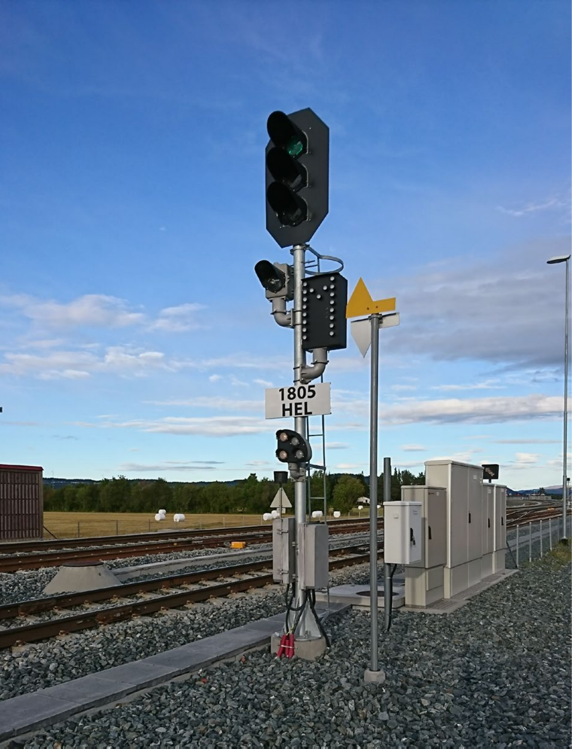
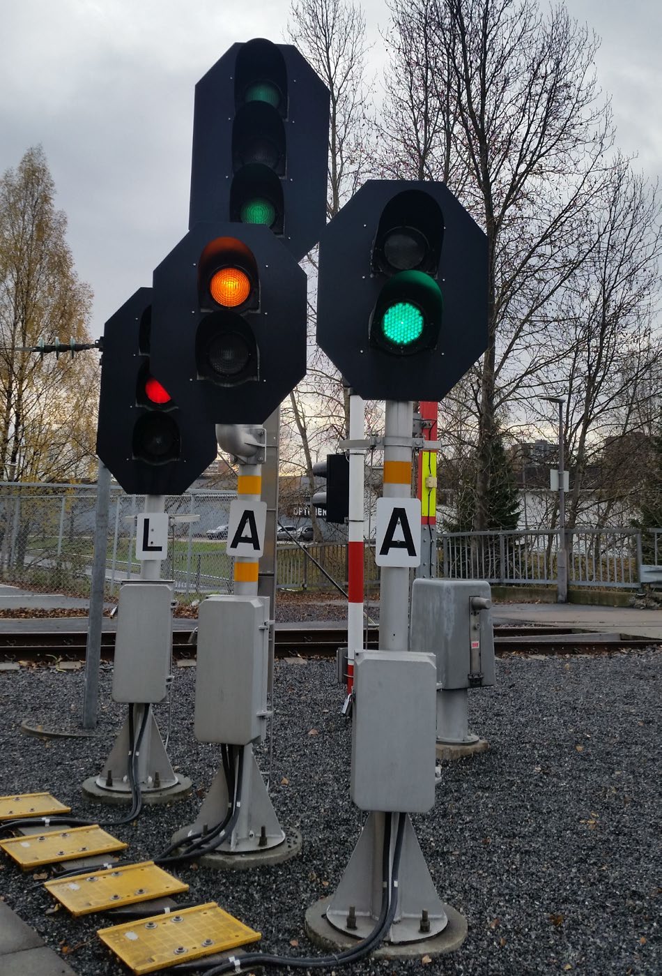
The mast in Figure 13.5(a) carries several signal functions above the equipment cabinets. The closer view in Figure 13.5(b) shows the main and distant signal heads, their background plates and lamp hoods. Use the standard aspect drawings below to interpret the signals, rather than inferring a movement authority from the photographs alone.
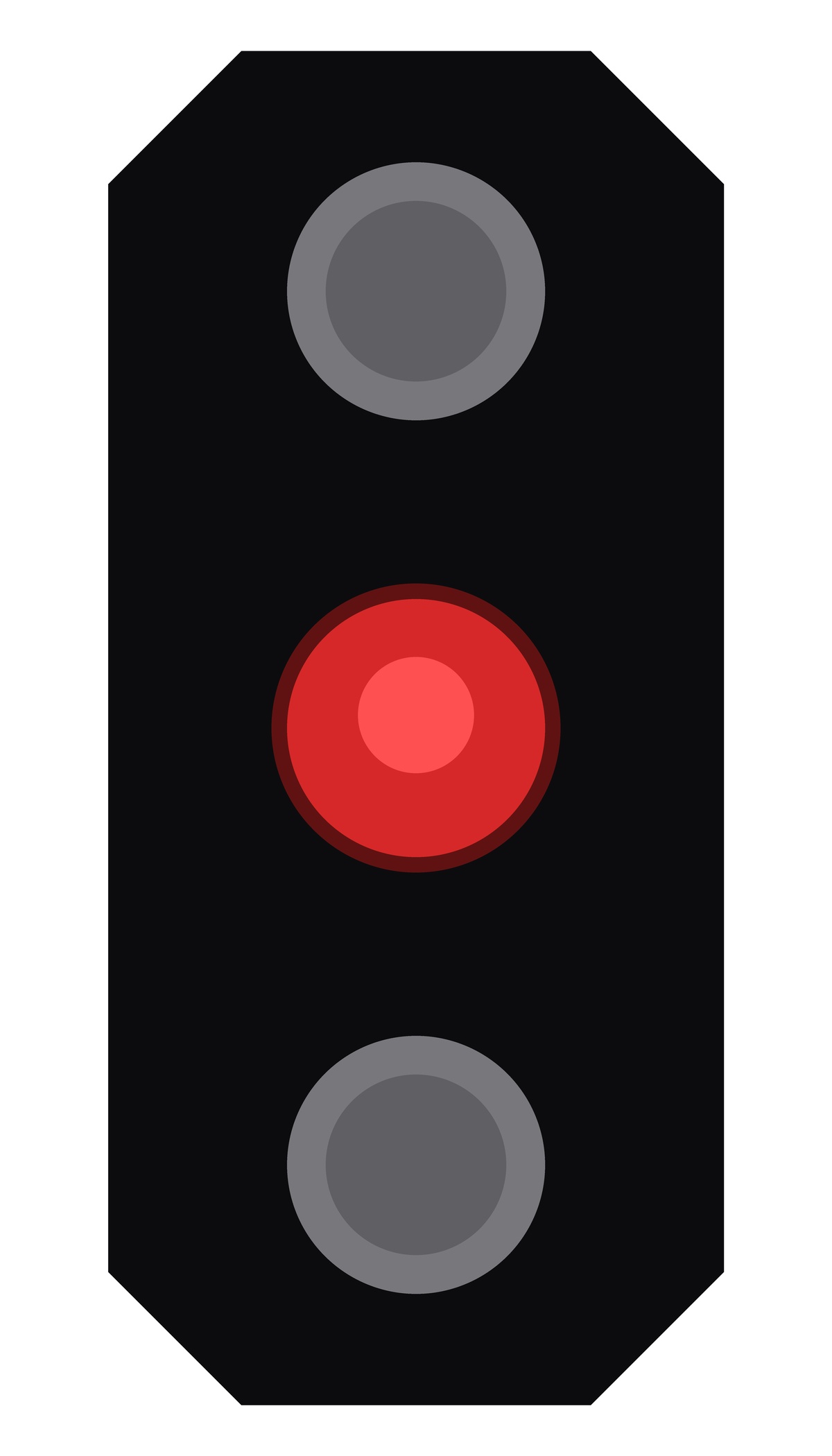
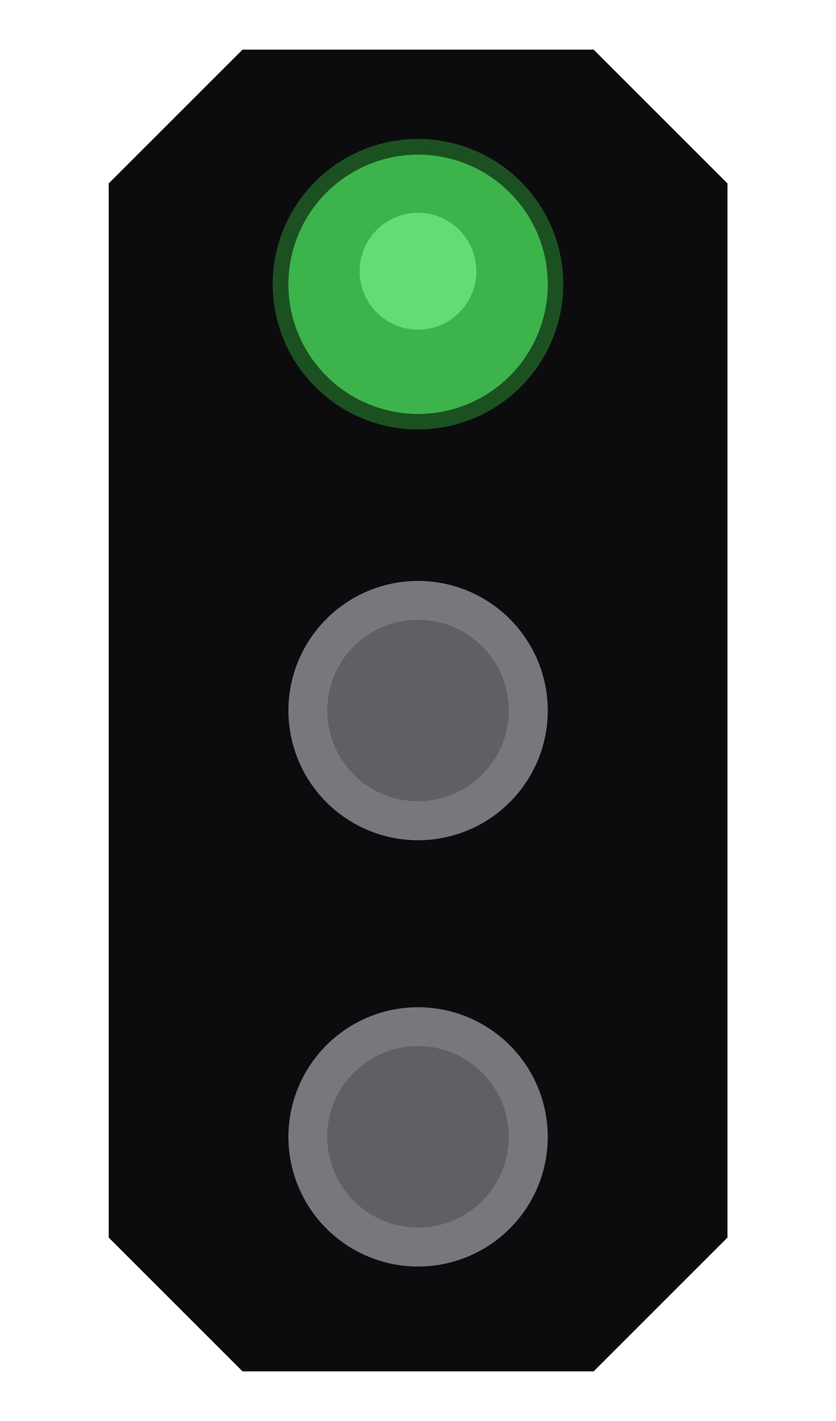
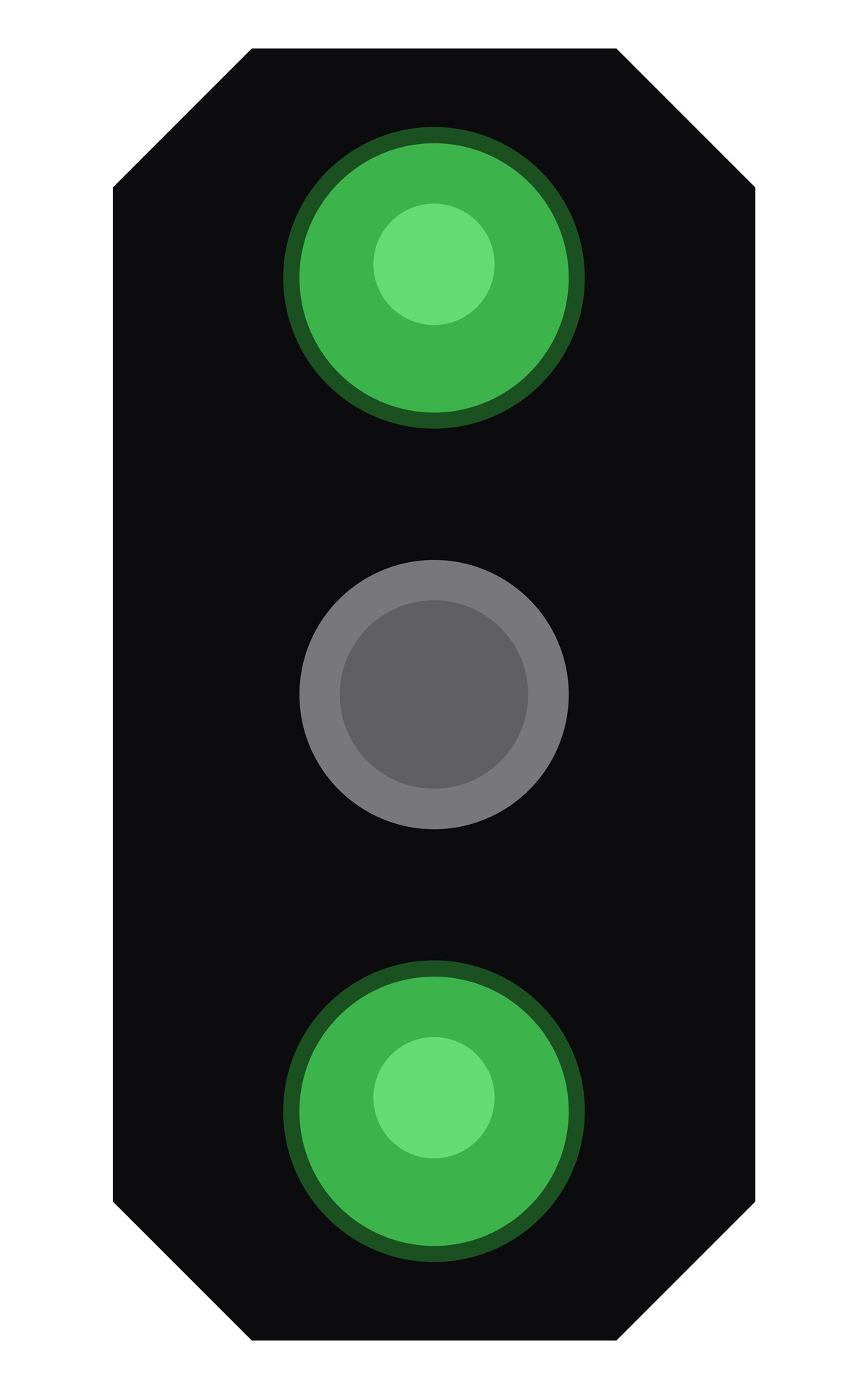
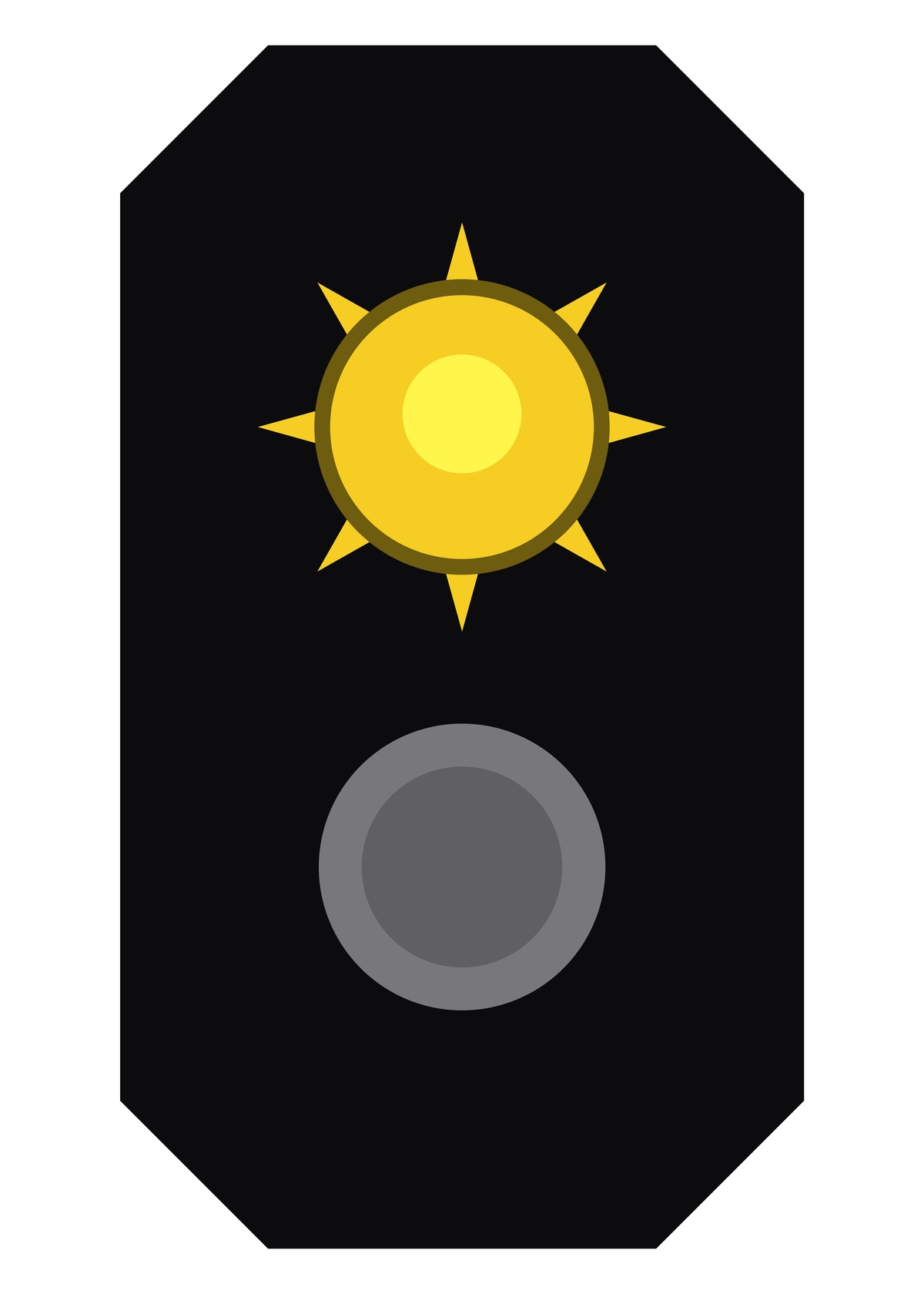
Bane NOR's operational rulebook includes visual examples for the individual signal types. Figure 13.6 reproduces a few common main-signal and distant-signal examples from the rulebook [57].
Main signals
reduced-speed proceed
proceed
Distant signals
expect stop

expect reduced-speed proceed
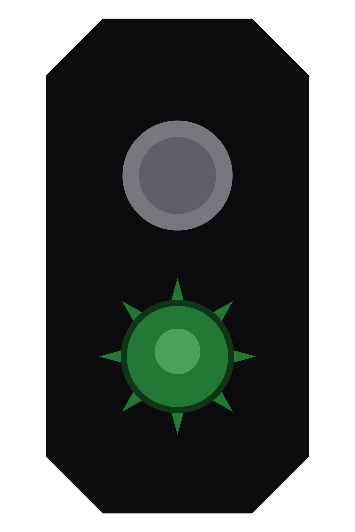
expect proceed
- Red
-
Stop or no permission to pass the signal.
- Green
-
A proceed aspect; the permitted speed is determined by the full aspect, route and applicable speed information.
- Yellow
-
Caution, not permission to proceed in its own right. A flashing yellow distant signal means expect stop; flashing yellow and green together mean expect proceed at reduced speed.
- White
-
Used in shunting and auxiliary signal contexts.
- Violet
-
The associated level-crossing signal shows "Stop in front of level crossing".
In Figure 13.6(a), the main signal requires a stop; 13.6(b) permits movement at reduced speed, while 13.6(c) gives the proceed aspect. The distant signals provide advance information: expect stop in 13.6(d), expect reduced-speed proceed in 13.6(e), and expect proceed in 13.6(f). They do not replace the authority at the main signal. The detailed rules must be taken from the current Bane NOR operational rulebook.
13.3 Traffic Management and Centralised Traffic Control
Traffic management is the operational layer above the interlocking. The interlocking decides whether a requested route is safe; traffic control decides which route should be requested, for which train, and at what time.
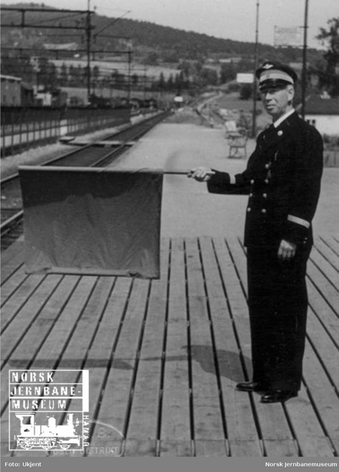
Earlier operation depended heavily on station staff communicating and checking train movements locally. The hand signal in Figure 13.7 illustrates this direct role in train dispatch. Modern interlocking and line block provide technical barriers in addition to the staff's actions. A local signaller still has an operational task, but the presence of a person at a station does not replace the safety functions of the installation.
It is useful to separate three related terms:
- Local control
-
A signaller or station operator sets routes from a control panel at the station. The station interlocking still proves the route before any signal can clear.
The modern station scene in Figure 13.8 illustrates that local signallers still work at some Norwegian stations. Their duties depend on the operating method and the equipment available; local staffing and technical train protection are separate questions.

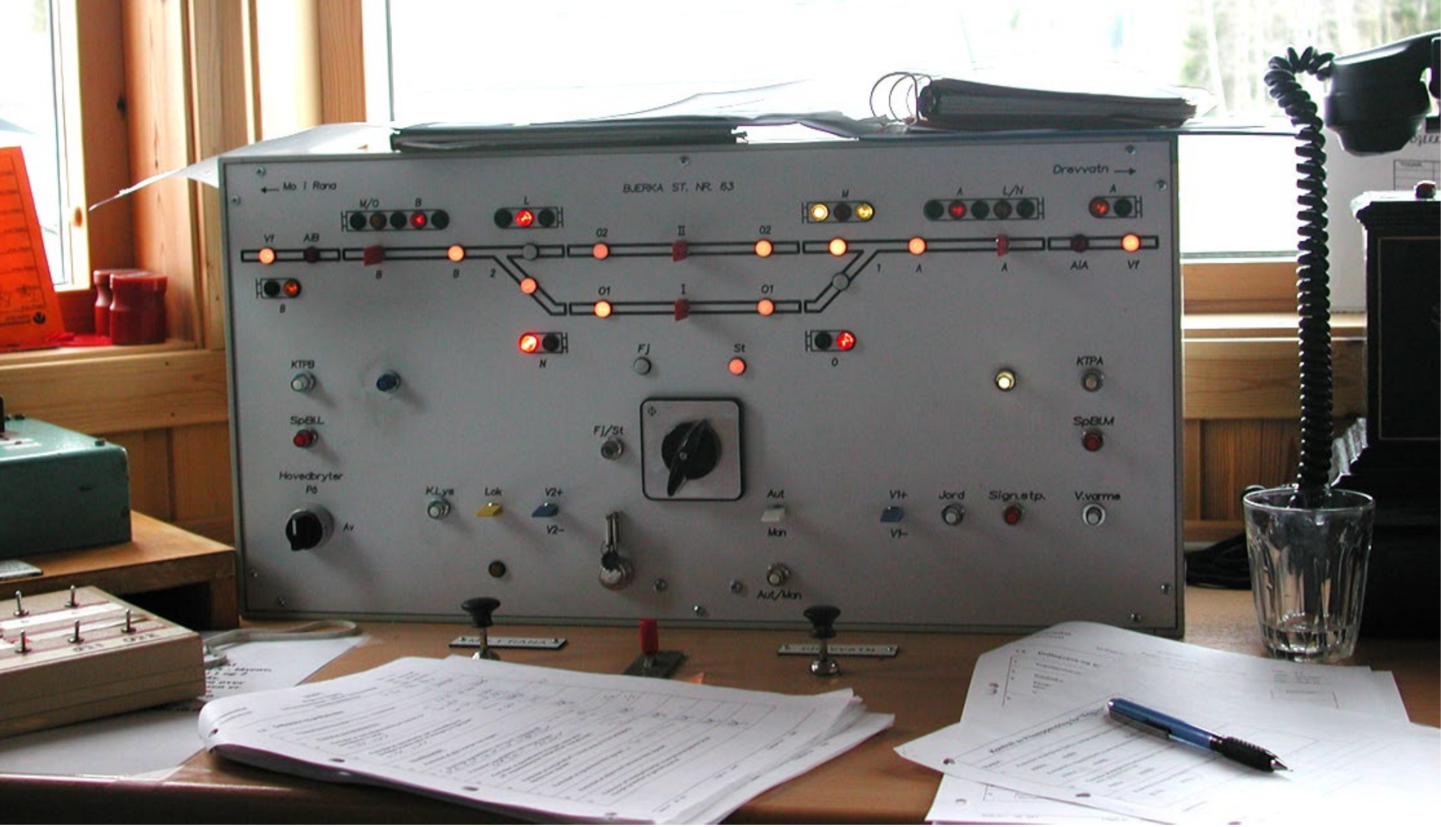
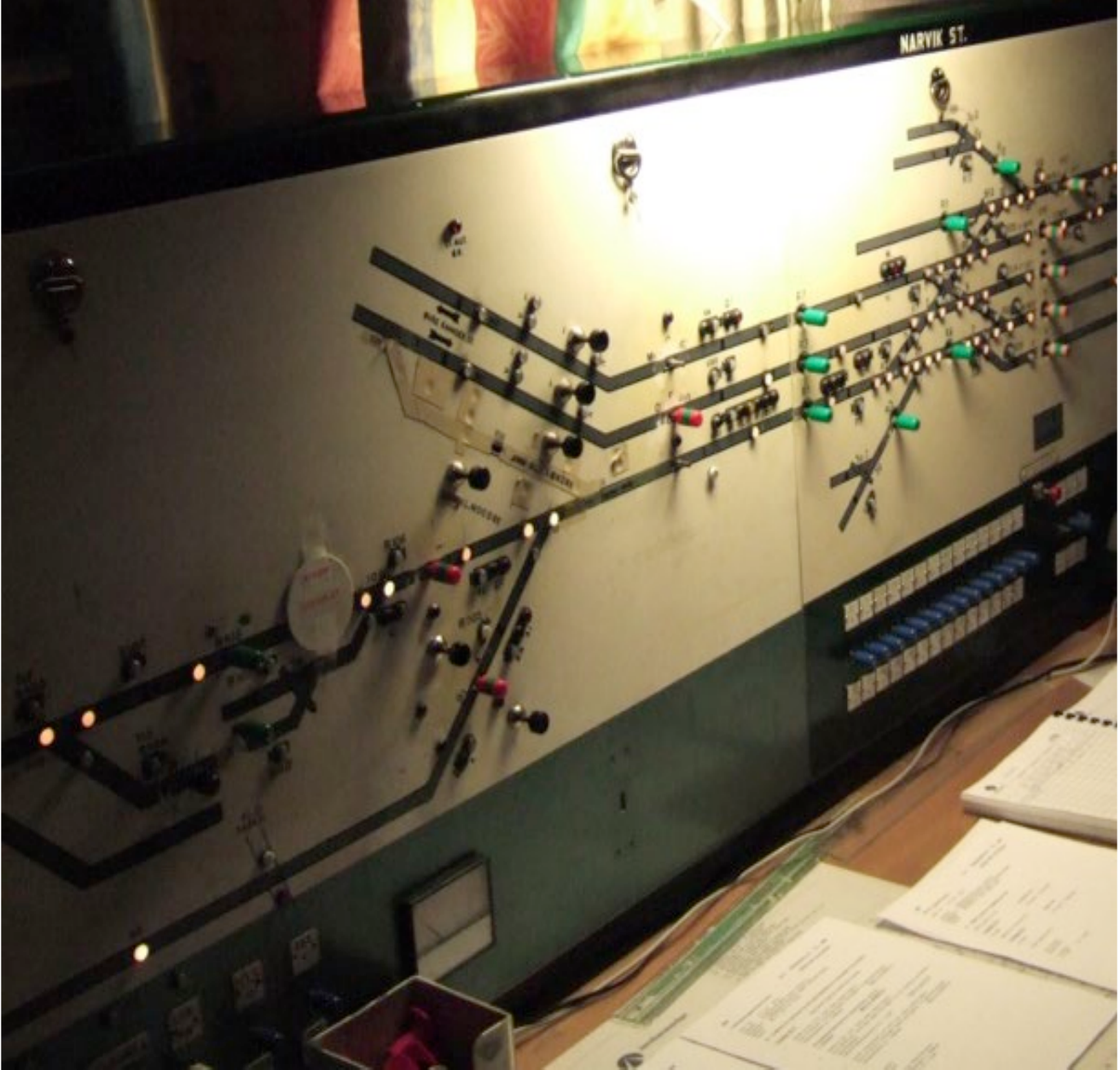
The track diagram in Figure 13.9(a) links the operator's request to the physical layout. The closer view in Figure 13.9(b) shows the controls and indications: the operator requests a change, and the indications report the states received from the equipment. A command to move points or set a route remains subject to the interlocking's checks.
- Remote-controlled station
-
Commands and indications are transmitted between the traffic-control centre and the signalling equipment. Conventional installations generally retain a station interlocking and a local control panel. In the national ERTMS architecture, central interlocking equipment connects to trackside object controllers, so a separate local interlocking and panel at every station must not be assumed. See Bane NOR's ERTMS architecture [249].
- Centralised traffic control (CTC)
-
One dispatcher supervises and controls several remote-controlled stations and line sections from a traffic-control centre. The dispatcher sees the traffic situation, requests routes and handles disturbances, while the interlocking continues to perform the safety checks.
Traffic control in Norway
The earlier organisation had eight dispatcher areas: Narvik, Trondheim, Hamar, Oslo, Drammen, Kristiansand, Stavanger and Bergen. These are historical locations, not a count of today's control centres. Bane NOR's Network Statement 2026 lists three dispatcher areas (East, South-West and North) and four traffic-control centres: TSS East Drammen, TSS East Oslo, TSS North and TSS South-West [254].
The operational organisation must also be distinguished from the location of the technical systems. The legacy arrangement placed technical equipment in Trondheim (Railmanager), Oslo (VICOS/EBICOS) and Drammen (VICOS). A server location is not an additional dispatcher area or a count of the people on duty. The transition to the national TMS changes the technical platform; it does not remove the distinction between traffic management and interlocking.
The workstation detail in Figure 13.10 shows the screens used to supervise train movements and interact with centralised control systems. The local panels and central workstation illustrate different operating interfaces to the signalling system. Remote control does not mean that every station is staffed locally around the clock.

In practice, CTC provides the live traffic picture: train positions, track occupancy, points, signals, locked routes, alarms and conflicts. It also supports remote route setting and functions such as pre-set or time-delayed crossing sequences, where a crossing manoeuvre is prepared in advance and executes when the required track sections and route conditions are available. A Traffic Management System (TMS) adds a planning and regulation layer on top of CTC, using timetable data, train describers and decision support to help dispatchers prioritise trains and recover from disturbances. Norwegian installations have used different generations of such systems, including names such as VICOS, EBICOS and Railmanager; these names are examples of platforms, not the central concept to memorise.
Remotely controlled line sections
Remote control applies to connected stations and line sections, not automatically to every line on the network. Most Norwegian lines are remotely controlled. Bane NOR distinguishes conventional remote control, where movement authority is conveyed by main signals, from ERTMS operation, where it is conveyed to the driver's display. On lines operated by train messages, station staff exchange prescribed messages to regulate train movements [254].
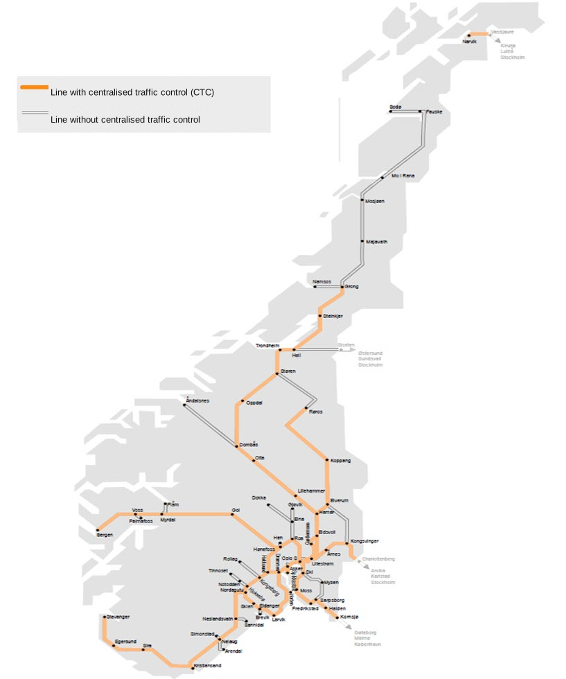
The historical map in Figure 13.11 illustrates the geographical distinction, but predates subsequent upgrades and is not a current operating map. For the latest line-by-line status, consult Bane NOR's operating-method overview, which links to the current SJN lists [255]. Remote control and train detection are different attributes: the map alone does not establish whether a line uses track circuits, axle counters, ATC or ETCS.
13.4 Fail-Safe Principle
The fail-safe principle is fundamental to all railway signalling. A signal may display a proceed aspect only when the required safety conditions have been proved. An unresolved condition prevents normal permission to proceed, but is not necessarily a signal failure: an occupied track section, for example, may simply mean that a train is present.
Fail-safe design aims to put the system into a defined safe state after a relevant failure, for example by withdrawing permission to proceed. This does not mean that every failure produces an illuminated red signal: loss of power can leave a signal dark, which must be handled under the applicable operating rules. Safety depends on the complete design and its verified failure behaviour [210].
The contact positions in a relay circuit drawing are reference states, not an instruction to clear a route in that state. Setting a route establishes and proves the necessary dependencies before locking them. A failed indication can originate in train detection, a point that has not reached its commanded position, power supply, communication or another interface. Diagnosing the cause and restoring operation must follow the applicable rules, without bypassing the protection.
Reading the train-route circuit
The circuit example in Figure 13.12 connects a route-setting request to a chain of electrical conditions. The magenta trace highlights a path through contacts and relay functions. The associated track diagram identifies the objects whose states the circuit must check.
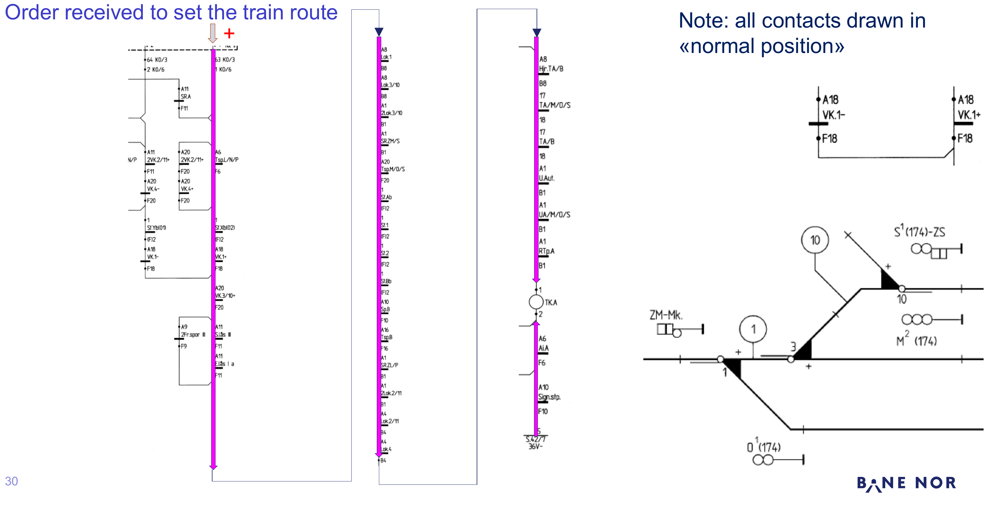
- Locate the incoming route-setting request and its supply connection.
- Follow the highlighted path through the contacts. A series path requires every relevant contact condition to be satisfied. A parallel branch represents an alternative only where the designed logic permits it.
- Relate the contact functions to the signals, points and detection sections in the layout. Contacts are drawn in their stated normal reference positions, which need not be their positions after a route request.
- Identify the output that can energise only when the required path is complete. An interrupted proving path prevents that permissive output.
This illustrates how dependencies become an electrical circuit. It is not an installation-specific wiring instruction or proof that every possible failure is safe. That assessment requires the complete circuit, component properties and safety case.
13.5 Level-Crossing Systems
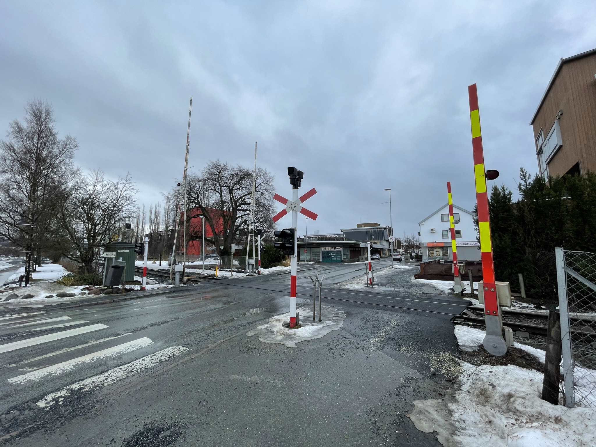
Level crossings are the interface between the railway and the road network, as shown by the protected crossing with lifting barriers and road-signal heads in Figure 13.13. Bane NOR material distinguishes protected crossings such as full-barrier, half-barrier and light/sound installations. At an introductory level, the protection can be grouped by intensity as follows [34]:
- Full barrier
-
Barriers block the entire roadway, supplemented by acoustic warning and road signals. Used on high-traffic roads.
- Half barrier
-
Barriers block the entry lane, which in Norway is the right-hand lane in the direction of travel. The exit lane remains open so that vehicles already on the crossing can leave. Acoustic warning and road signals.
- Road signal system
-
Acoustic and road signals only; no barrier.
- Warning lamp
-
Minimal protection; typically used for agricultural crossings with very low and predictable usage.
Bane NOR's operational rulebook also defines railway-side level-crossing signals for the driver. Figure 13.14(a) requires the driver to stop before the crossing, whereas 13.14(b) indicates that it may be passed. The distant indications announce the crossing signal's state: expect a stop before the crossing in 13.14(c), or expect permission to pass in 13.14(d). These crossing indications do not by themselves authorise the entire train route.
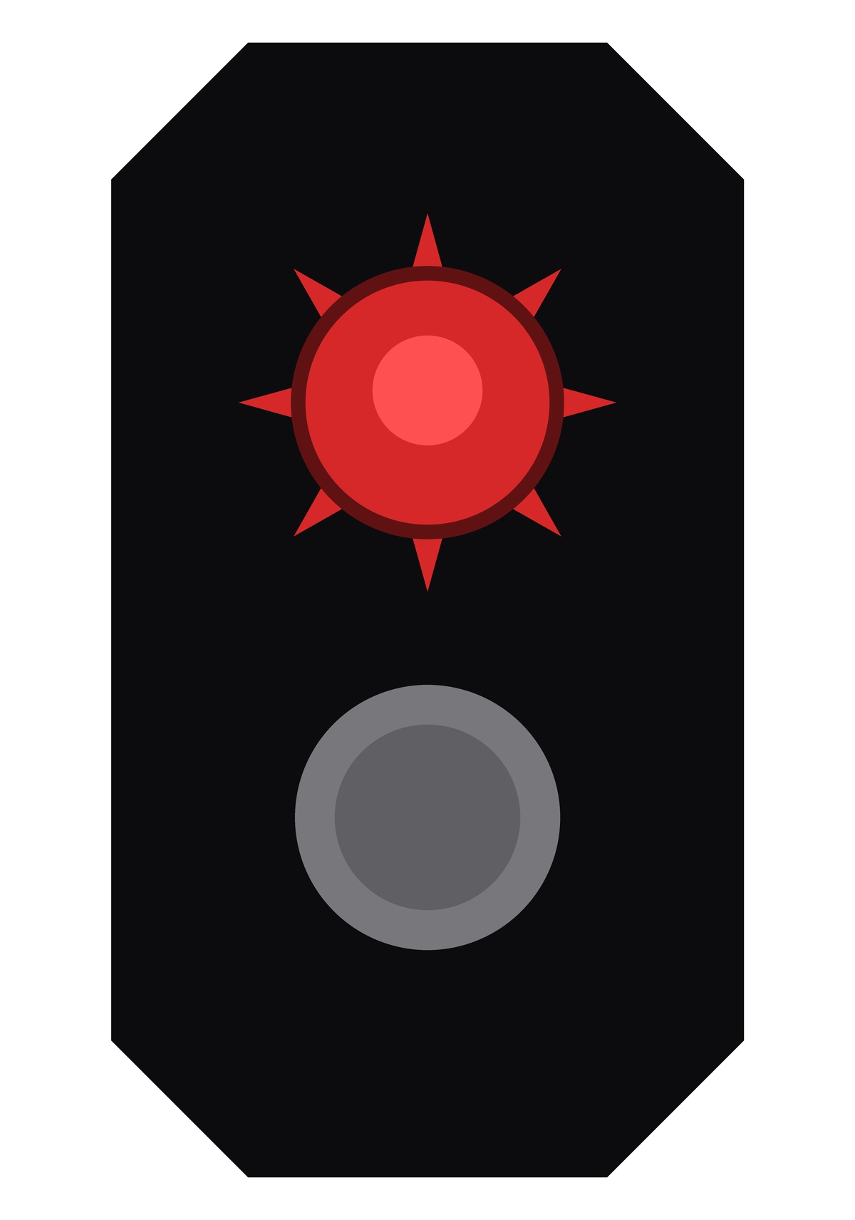
Stop before
level crossing
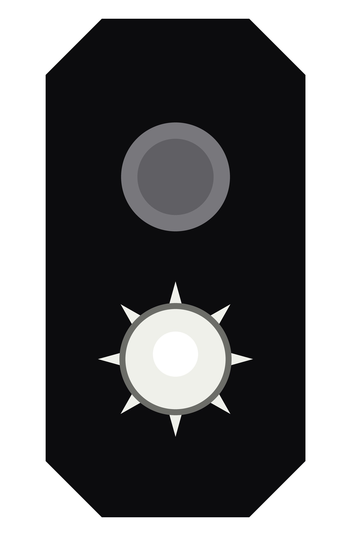
Crossing may
be passed

Crossing signal indicates
stop before crossing
Crossing signal indicates
crossing may be passed
Figure 13.15 shows activation when a train enters the approach zone (Activation point A) and deactivation after the train clears the crossing (Deactivation point A, with equivalent points on the other side of the crossing).

An approaching train must initiate warning early enough for road traffic to stop and for the equipment to reach the required state. The activation point on an approach differs from the release point after passage. The opposite direction uses the corresponding points on the other approach. A train stopping near the crossing must not cause the protection to be removed prematurely.
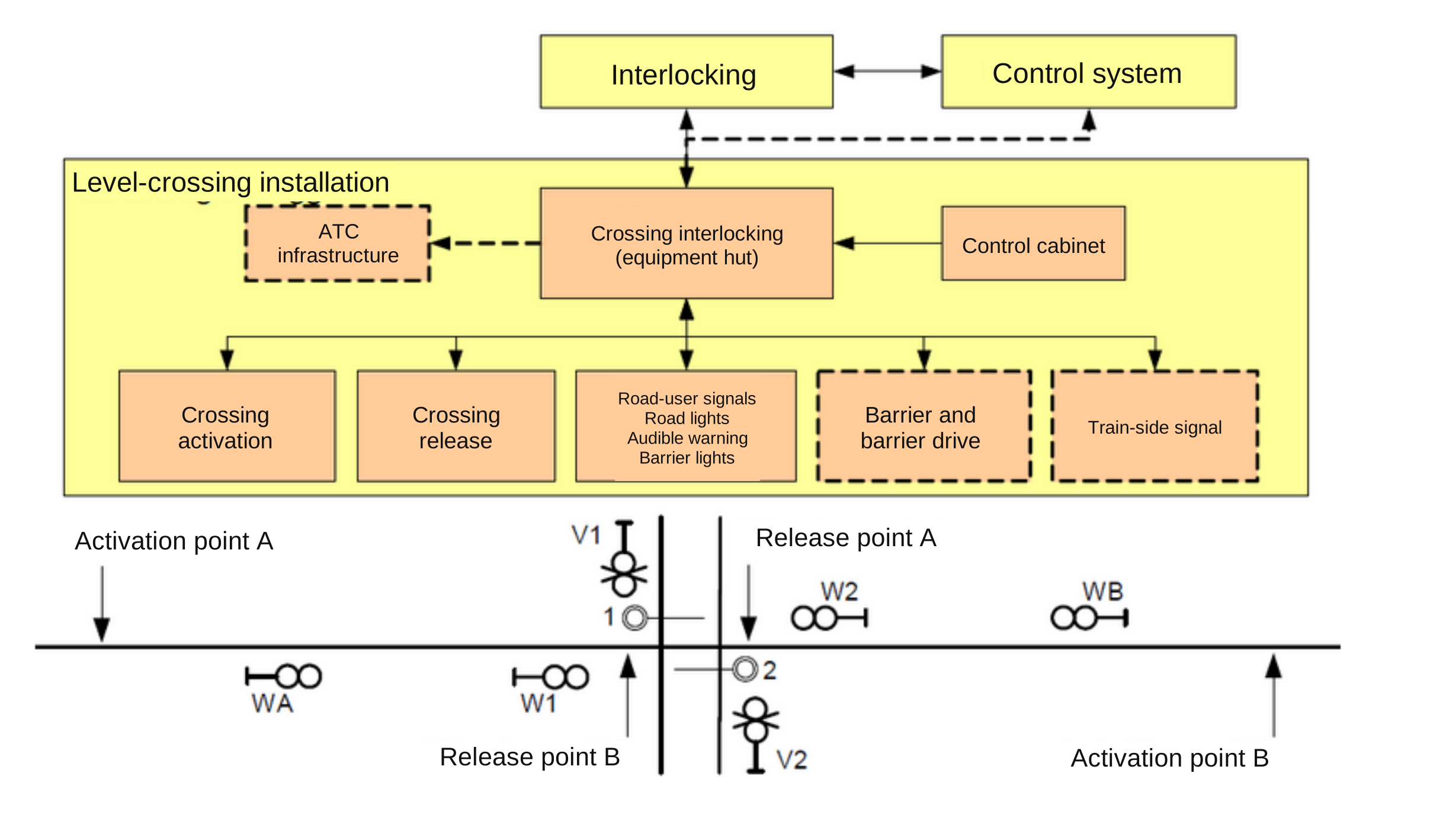
The functional diagram in Figure 13.16 separates the road-user warnings from the train-side interface. Road signals and audible warnings address road users. Barriers physically restrict access. Train-side signals or the relevant signalling interface indicate whether the conditions needed for the train movement have been proved. Detection and interlocking interfaces coordinate these functions. A command to start the warning does not by itself prove that the barriers have reached their required position.
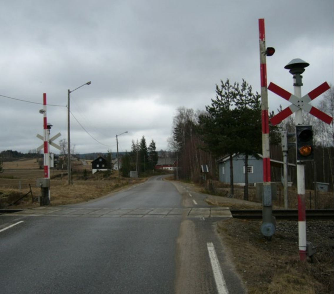
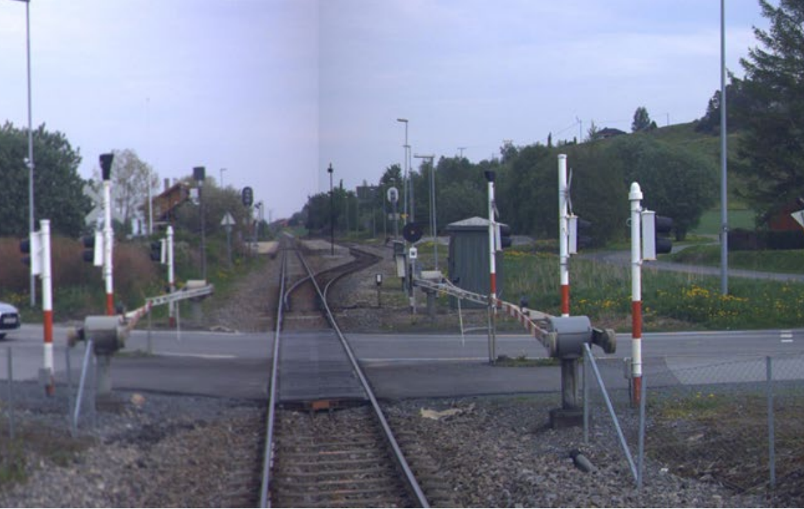
Figure 13.17(a) shows the signals and barriers encountered by road users; 13.17(b) shows the mechanisms beside the track. At a half-barrier crossing, the exit side remains available for a road vehicle already on the crossing. A full-barrier installation closes the road more completely, so its warning and proving arrangement must address the risk of trapping a vehicle. Selection depends on the road, traffic, train movements, sight conditions and surroundings.
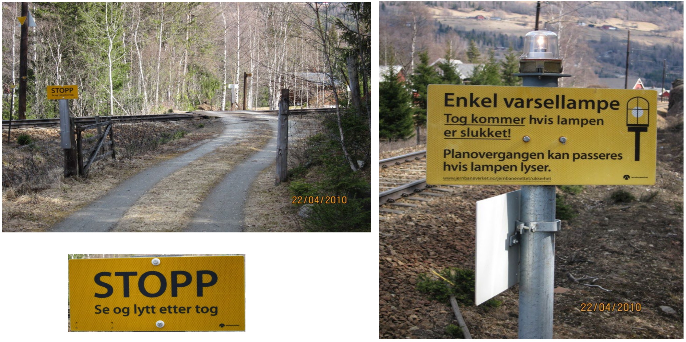
The gate and warning-lamp instructions in Figure 13.18 illustrate different protection from a public barrier crossing. The Norwegian stop sign means “Stop. Look and listen for trains”. The lamp sign warns that a train is coming when the lamp is unlit, and says that the crossing may be used when it is lit. Users must follow its signs and instructions. The lamp is not a general guarantee that crossing is safe under every circumstance.
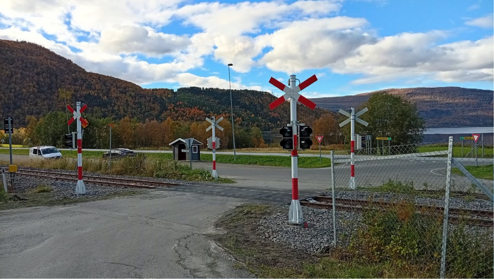
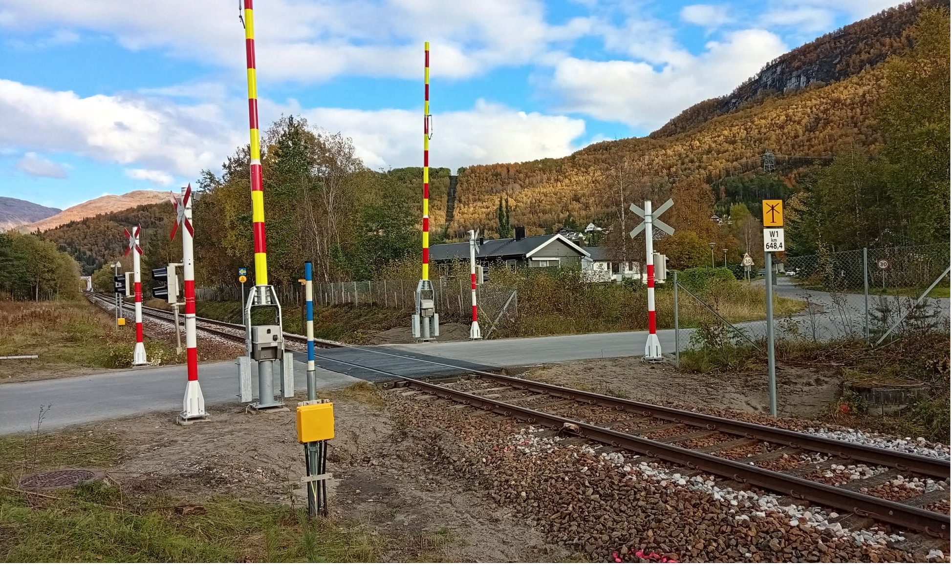
ERTMS changes the signalling interface to the train. The road-side equipment in Figure 13.19(a) and trackside equipment in 13.19(b) show that a physical crossing installation is still needed. The crossing still needs to warn road users and prove the relevant protection conditions. Cab signalling does not remove the physical conflict between road and railway.
13.6 Train Detection
The interlocking does not need a continuous map of the train; it needs reliable section states. Track is divided into detection sections, and each section is reported as clear or occupied before a route can be set. Figure 13.20 shows this basic principle before the two common detection technologies are introduced.

The two most common detection methods in Norway are track circuits and axle counters [10].
13.6.1 Track Circuits
Track circuits were introduced in Chapter 2 as one reason why rail-seat components, fastenings and insulated joints must provide reliable electrical insulation. Here the rails carry the detection current, and the interlocking uses the resulting section state as a safety input. The clear-state circuit is shown first. The occupied-state response is explained below, followed by the relationship to traction return.
The signalling interpretation is fail-safe: the receiver is energised only for a free section. When train axles shunt the rails, the receiver de-energises and the section is indicated occupied. Loss of the detection current also drives the system toward the restrictive state rather than toward a false "free" indication.
Simple circuit
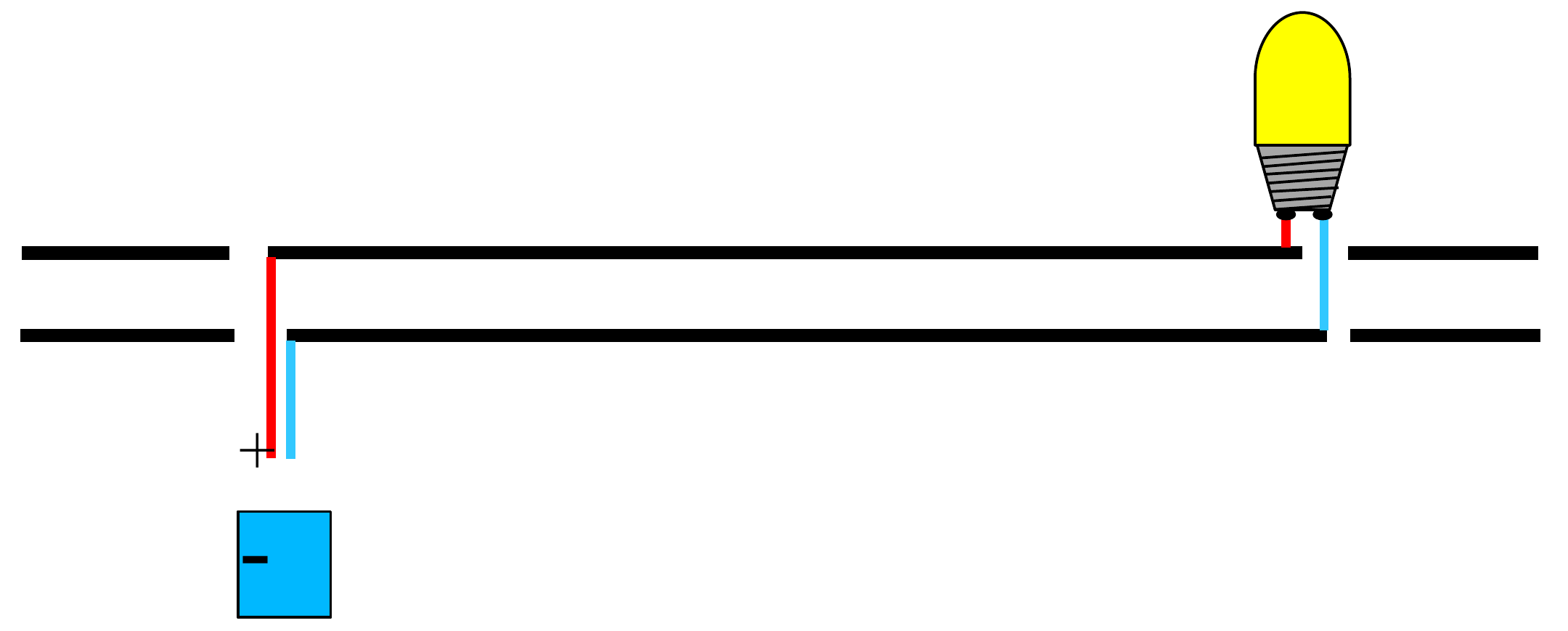
Insulated section, battery and relay
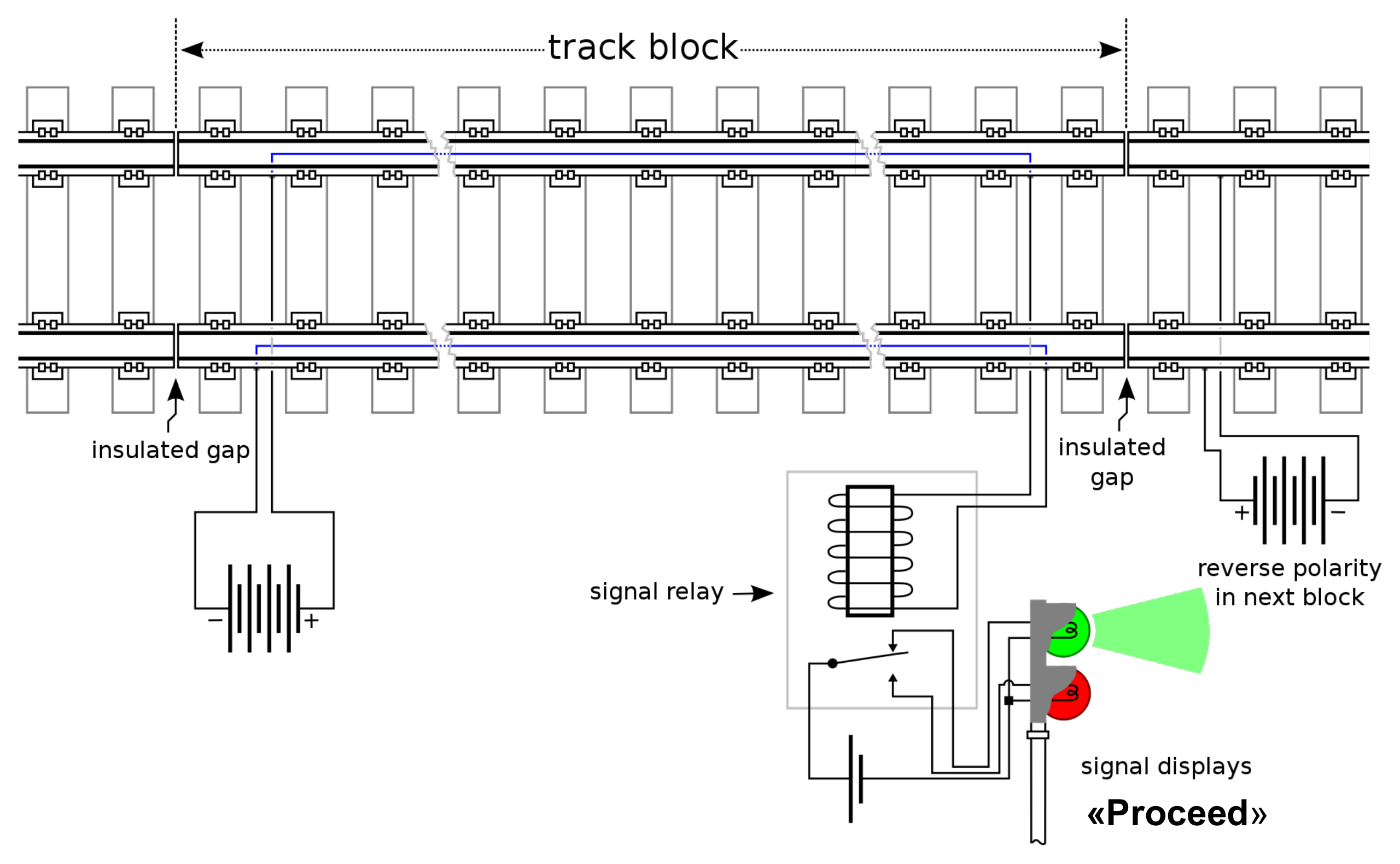
In the simple circuit in Figure 13.21(a), current reaches the receiver through the intended rail circuit. A conducting wheelset connects the two rails and shunts the receiver. The indication changes to occupied. The lamp represents the circuit state, not the complete aspect logic of a real signal.
Figure 13.21(b) relates this principle to the track itself. Insulated joints define the section boundaries. With no train present, current flows from the battery along one rail, through the track relay and back along the other rail. The energised relay holds its contact in the clear-state position. A conducting wheelset shunts the rails, reducing the relay current so that the relay releases and the section is indicated occupied. The neighbouring section is shown with opposite feed polarity. This is a conventional DC example, not a wiring diagram for every track-circuit type; the feed's current-limiting resistor is omitted. The green signal illustrates the principle only: a clear detection section alone does not authorise a train movement, and the drawing does not represent Norwegian signal aspects.
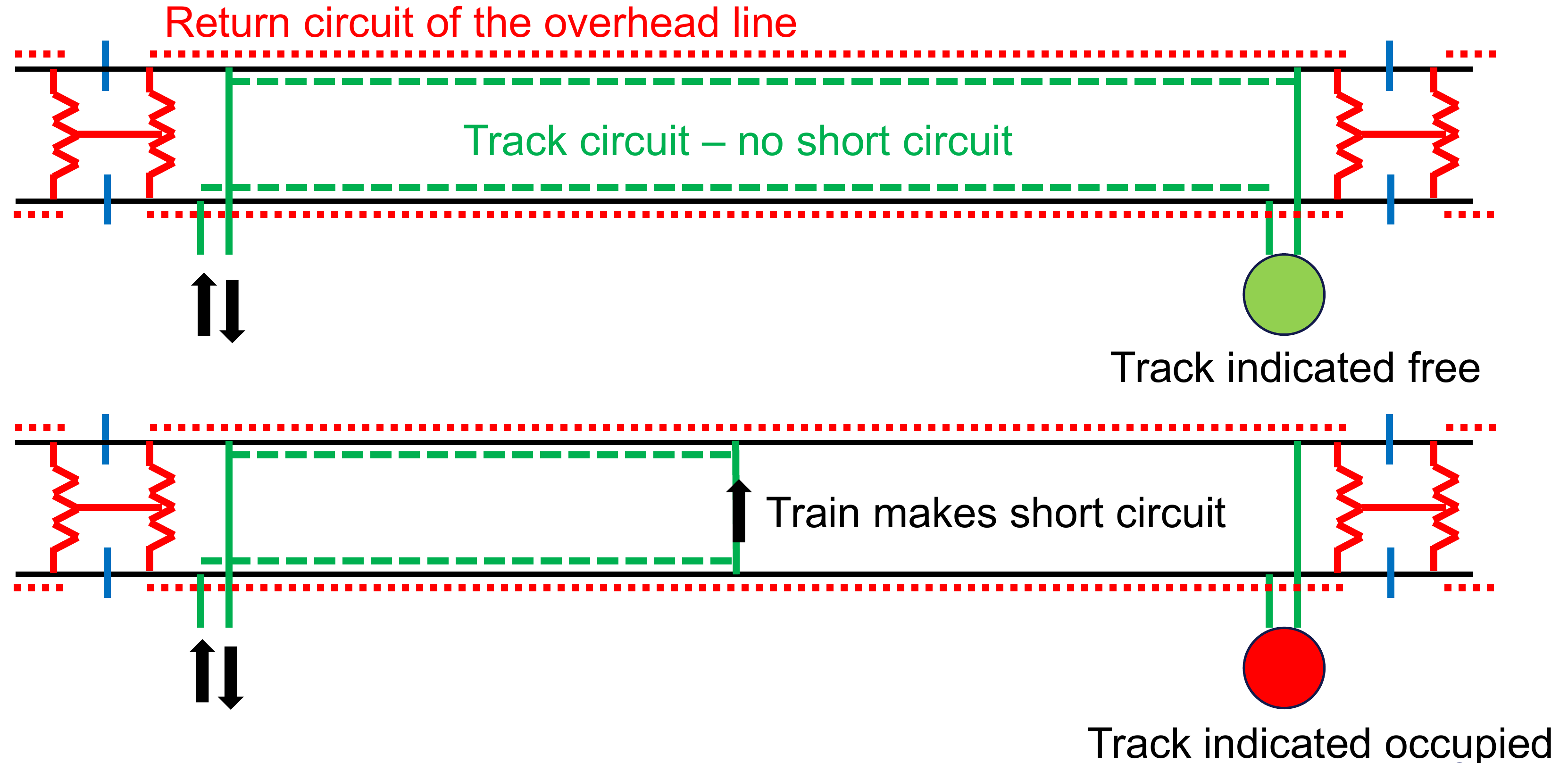
Figure 13.22 shows why detection and traction return must coexist electrically. On electrified lines the traction return current uses the rails; the track circuit must use a frequency different from the traction supply frequency (or use coded signals) to discriminate between train-detection current and traction return current. Insulated rail joints separate sections in jointed track-circuit designs. Jointless track circuits [211] use electrical separation arrangements without requiring an insulated joint at every boundary.
Limitations of track circuits include sensitivity to rail rust/oxidation (poor electrical contact), contamination (sand, leaves) which may falsely indicate "free", and, for designs that use them, the maintenance burden of insulated joints.
Insulated rail joint
Rail bond
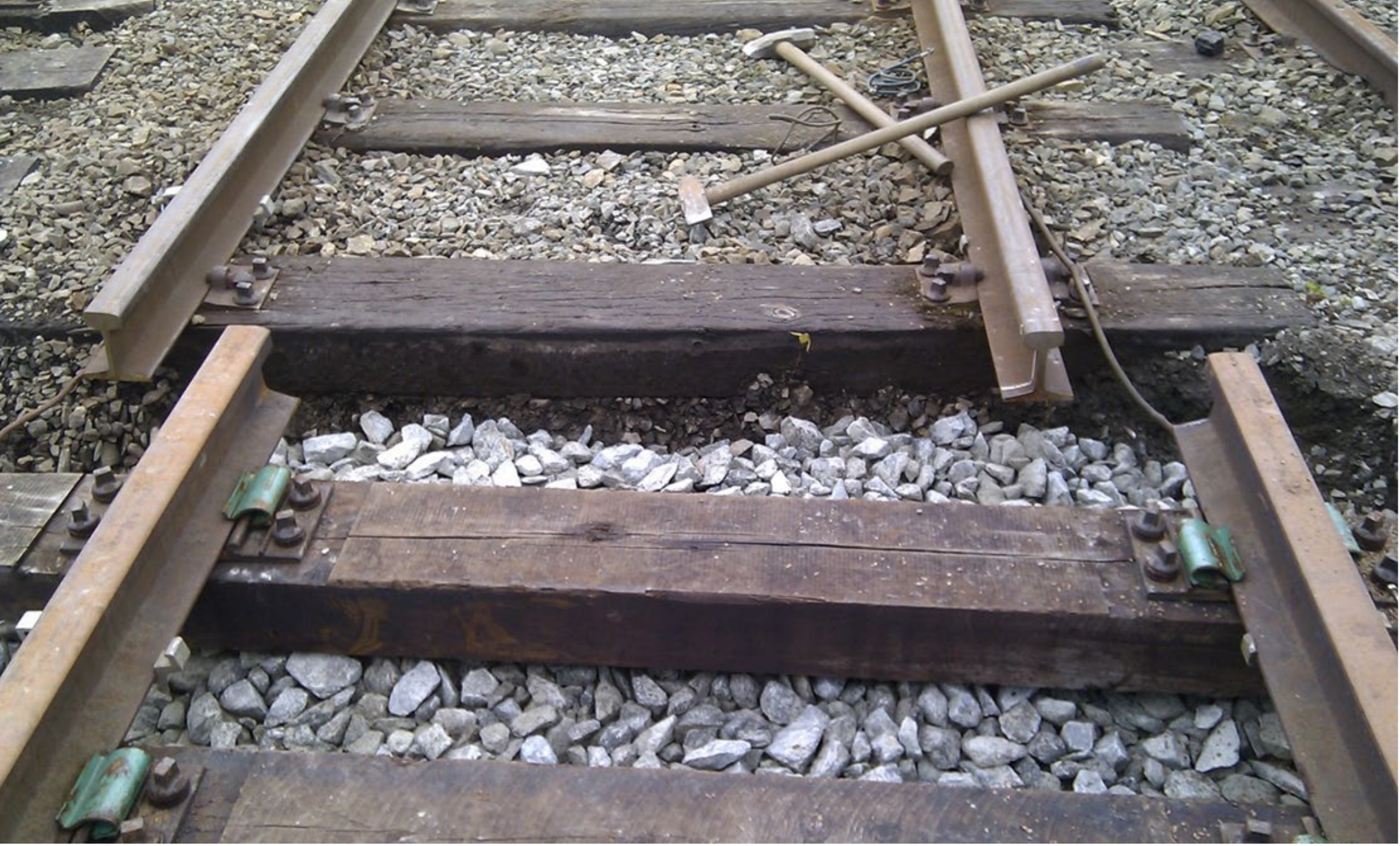
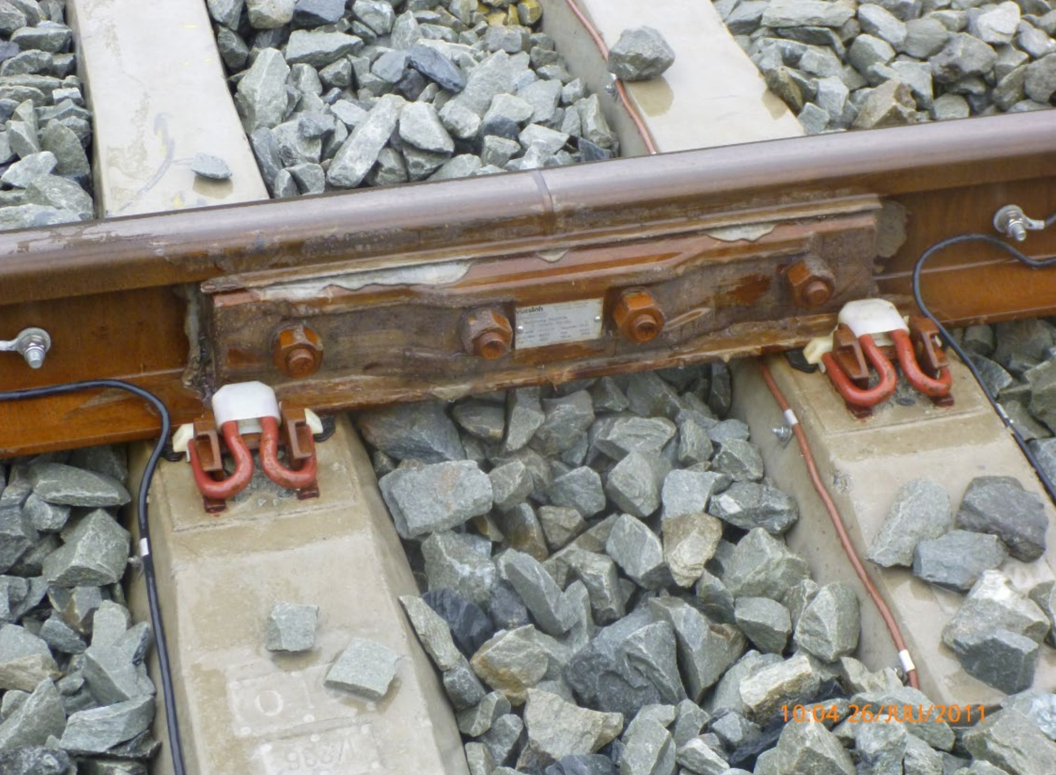
The insulated joint in Figure 13.23(a) is an electrical boundary and a mechanical rail connection. The bond in 13.23(b) provides a deliberate conductive path. These interfaces explain why signalling, traction return and track maintenance must be coordinated. Identify a connection's function from the actual circuit design before altering it.
13.6.2 Axle Counters
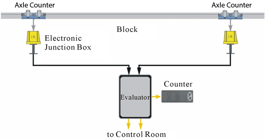
For axle counters, the key safety information is the balance between axles counted into and out of a detection section. The functional diagram in Figure 13.24 follows the counting points through the evaluator to the interlocking and operating interfaces.
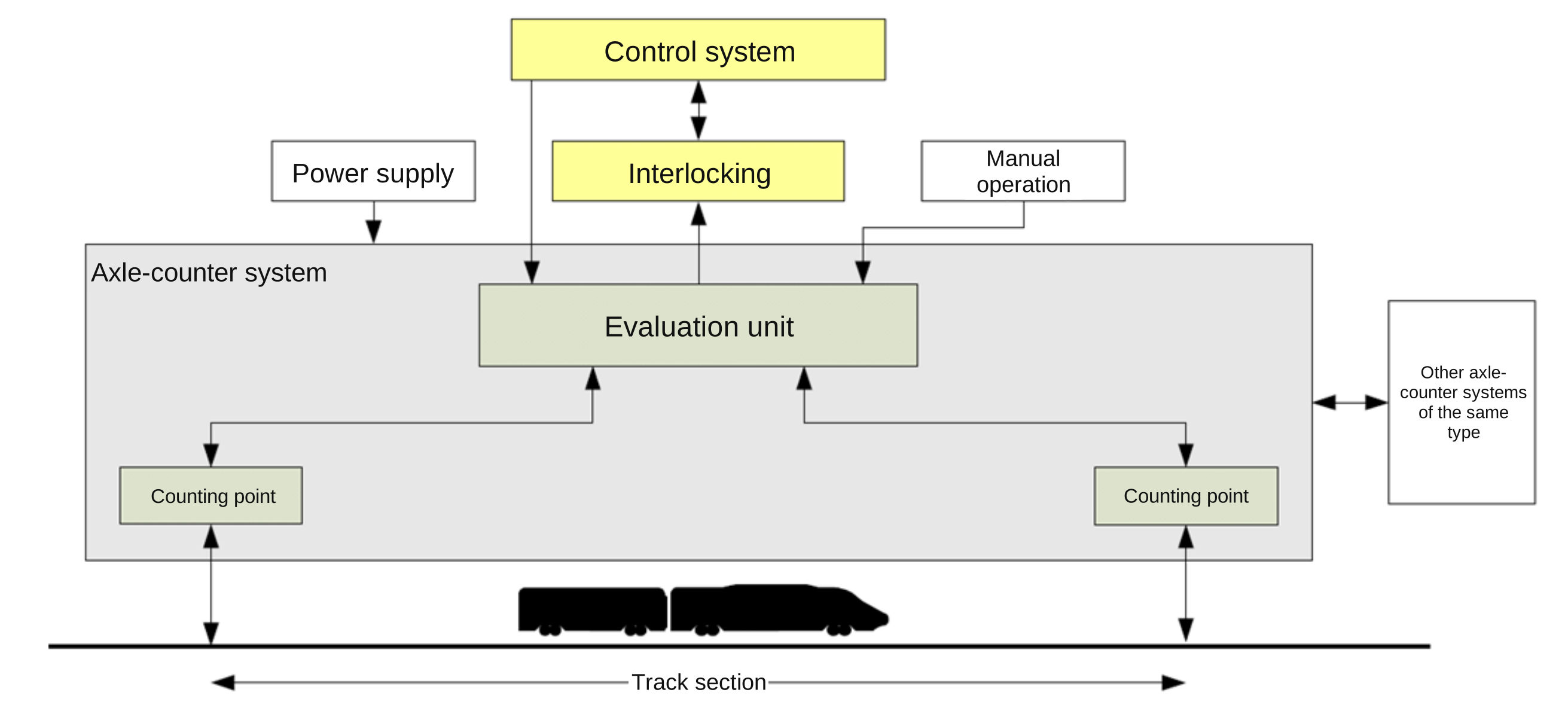
An axle counter detects individual axles by the disturbance they cause in a magnetic field generated across the rail head. Counting heads are installed at both ends of a detection section. The system counts axles entering and leaving:
-
Axle balance \(= 0\), with all validity checks satisfied: section clear.
-
Axle balance \(\neq 0\), or an inconsistent/invalid count: section occupied or failed and therefore indicated restrictively.
-
Balance returns validly to 0 after the complete train leaves: section clear again.
The trackside counting-head electronics provide power and determine the axle-passage sequence and direction. The evaluator combines the counts and reports the section state to the interlocking, as described in Bane NOR's train-detection requirements [247]. Axle counters do not require insulated rail joints and are less sensitive to rail contamination [148]. Snow and other environmental conditions can affect the equipment. If maintenance affects the counting state, restoring a valid clear indication may require a controlled reset under the applicable procedures.
Figure 13.25 shows that the counting heads observe passage at the section boundaries, not continuous occupancy throughout the section. A road-rail vehicle entering the track section must be registered as occupying the section to prevent a false "free" indication. Neither a track circuit nor an axle counter should be relied on to detect a kicksled or a pedestrian. These are train-detection systems, not systems for detecting people on the track.
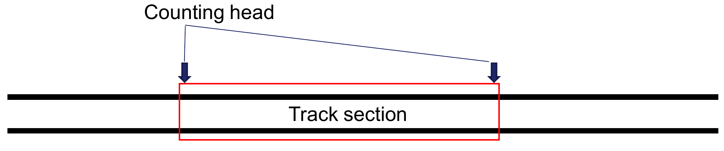
Figure 13.26(a) starts with a clear section and a zero balance. Two entering axles give a balance of two in 13.26(b), and the complete four-axle train gives four in 13.26(c). As axles leave, the balance falls to two in 13.26(d), then returns to zero in 13.26(e). Only a valid count permits a clear indication again. The number is the balance of axles counted in but not yet counted out. It is not a continuous measurement of the train's location.





The section remains occupied after the front has passed the exit head. It can return to clear only when the complete train has passed and the counting and validity conditions are satisfied. An inconsistent count or equipment fault requires a restrictive indication. Resetting is a controlled procedure, not simply forcing the displayed number to zero.
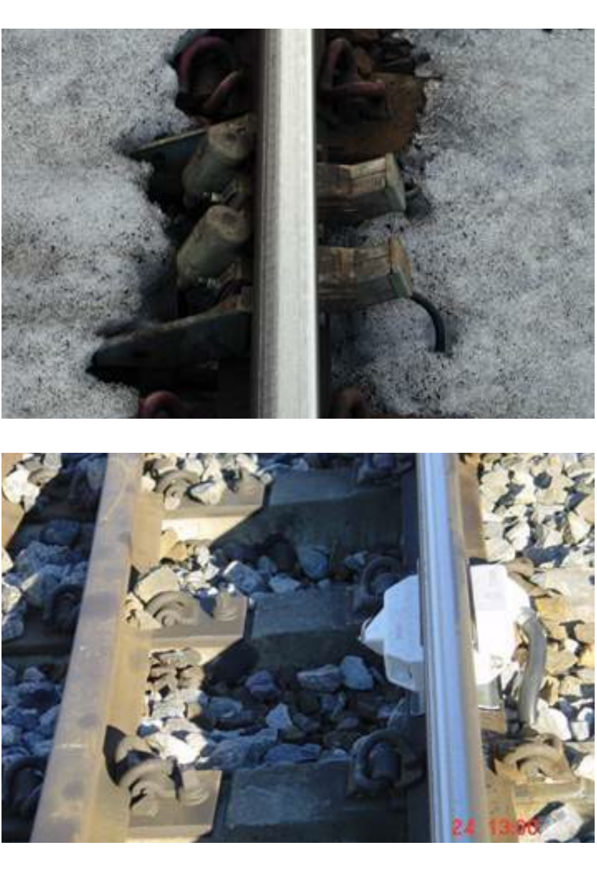
Counting heads
Trackside electronics
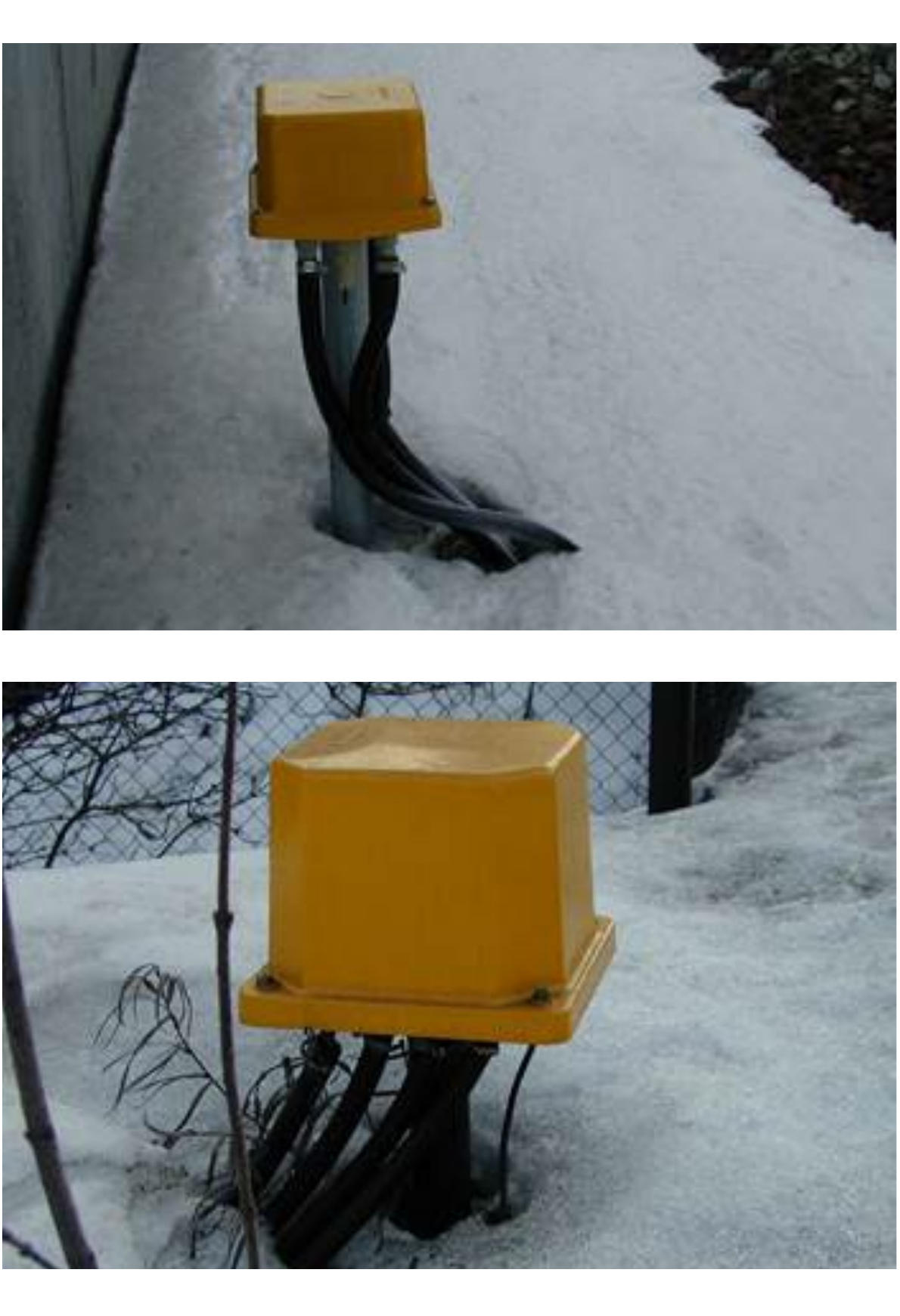
The counting heads in Figure 13.27(a) sense the passing wheels. The associated trackside electronics in 13.27(b) supply and process the signals, including the sequence used to establish direction. The evaluator combines information from the boundaries and supplies the section state. These functions can be distributed differently between products.
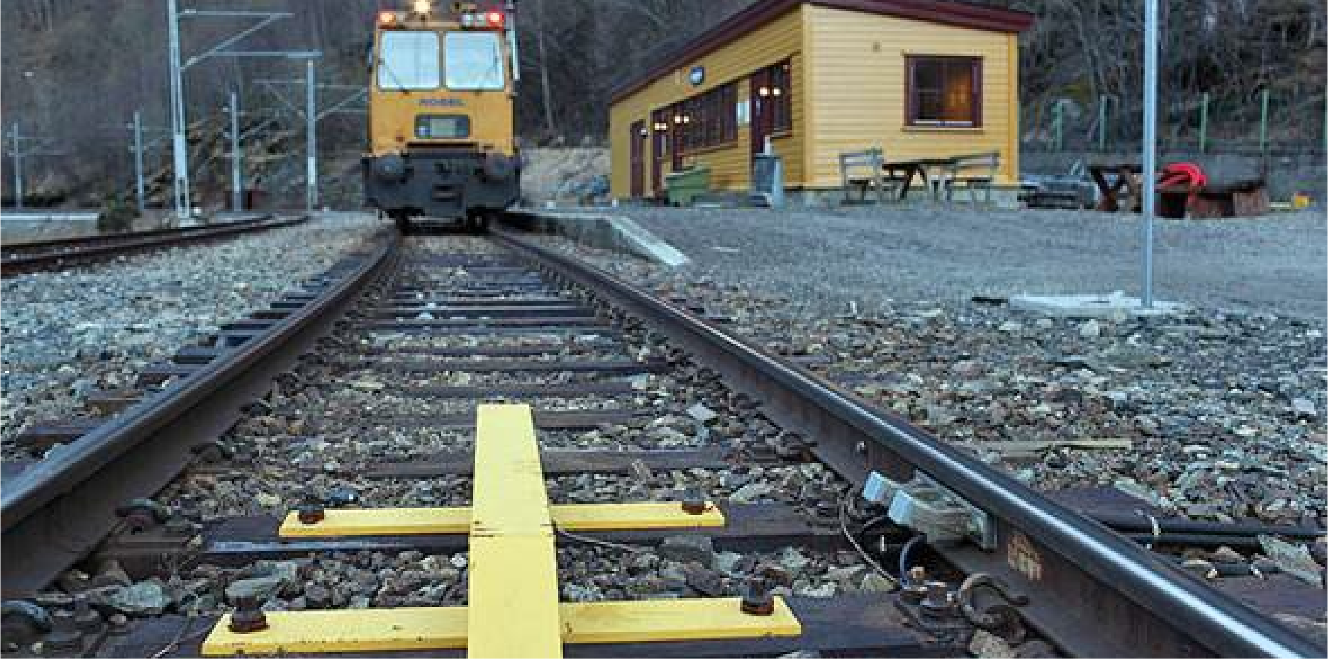
The protection around the equipment in Figure 13.28 illustrates that the installation must withstand snow clearance and maintenance work. This photograph is an installation example, not evidence that axle counters are unaffected by every winter failure mechanism.
Three practical cases help compare the technologies. A small object or kicksled must not be assumed to produce a reliable track-circuit shunt. A road-rail vehicle entering within a section may not have passed its boundary counting heads. Rust can impair a wheelset's electrical shunt, whereas axle counting relies on detection at the counting points. Work planning and operating rules must cover these cases rather than assuming that either system detects every intrusion automatically.
13.7 Point Machines and Flank Protection
A point machine (switch machine) is the electromechanical actuator that moves the switch blades of a set of points and provides a locked, detected position to the interlocking. For signalling, the important information is not the physical machine type but whether the point has reached and locked in the commanded position before a route depending on it can be cleared. The switch blades, stock rails and crossing components controlled by the point machine are described as track components in Chapter 16.
Figure 13.29(a) shows a conventional open-drive unit. The sleeper-mounted unit in 13.29(b) contains the mechanism within the sleeper; the open view in 13.29(c) makes that arrangement visible. The packaging differs, but all three views concern equipment that must move, lock and detect the points.
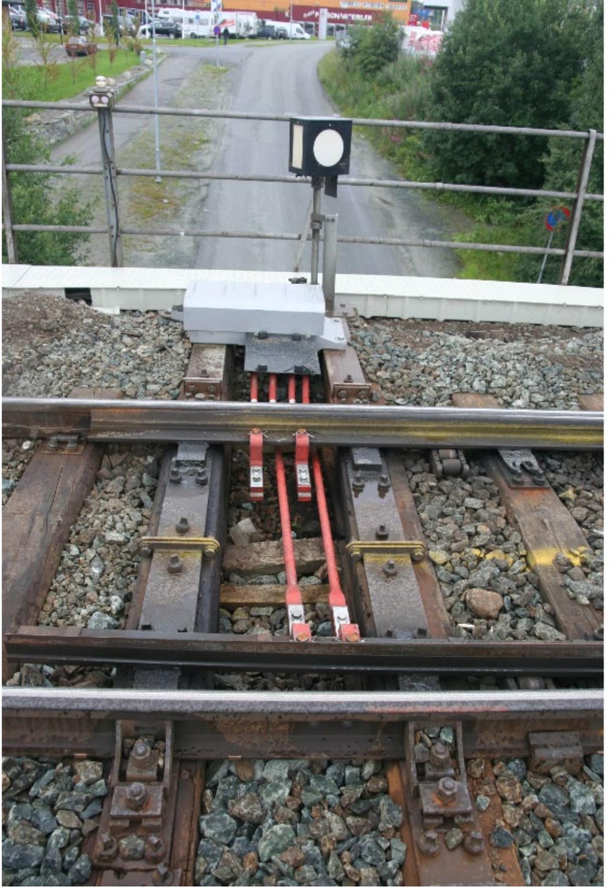
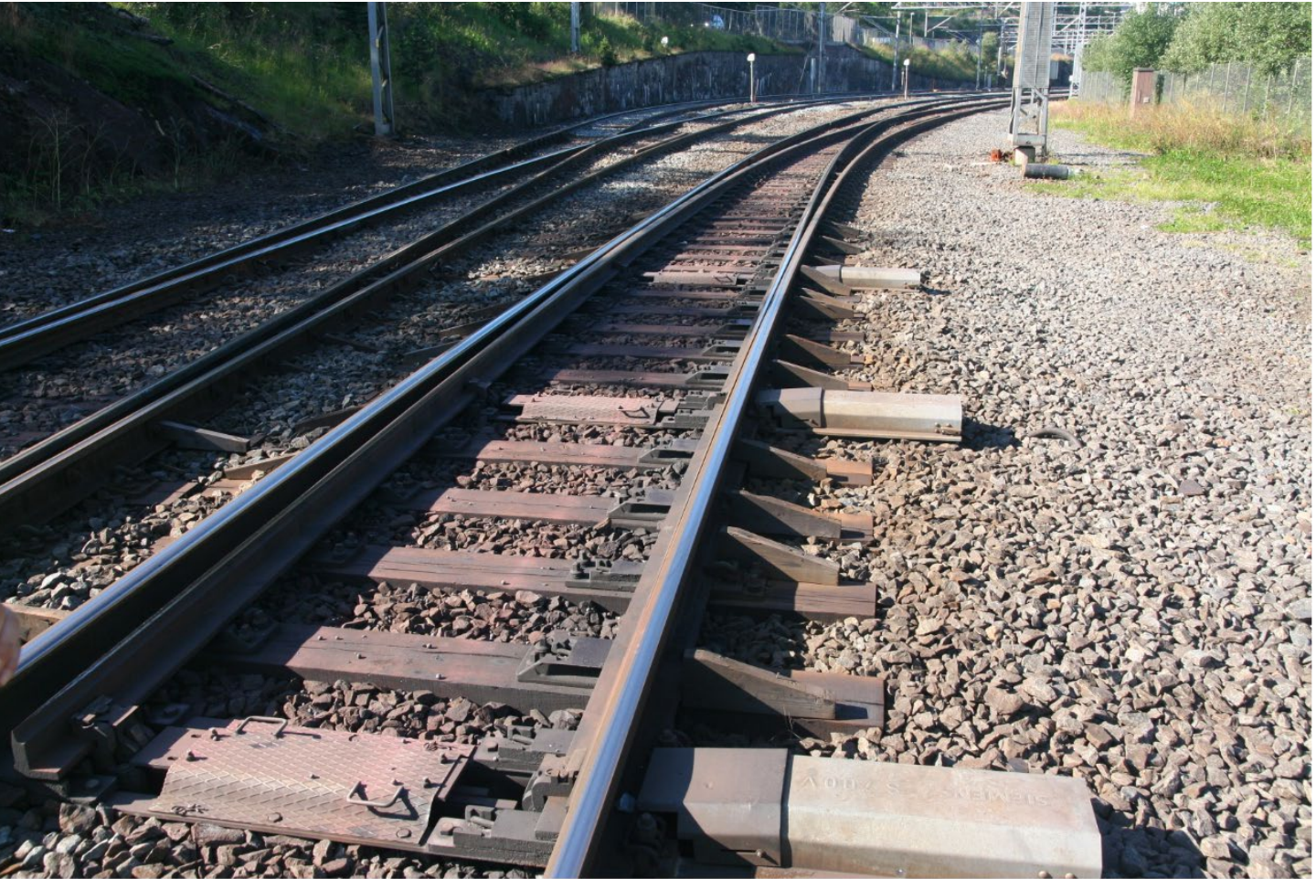
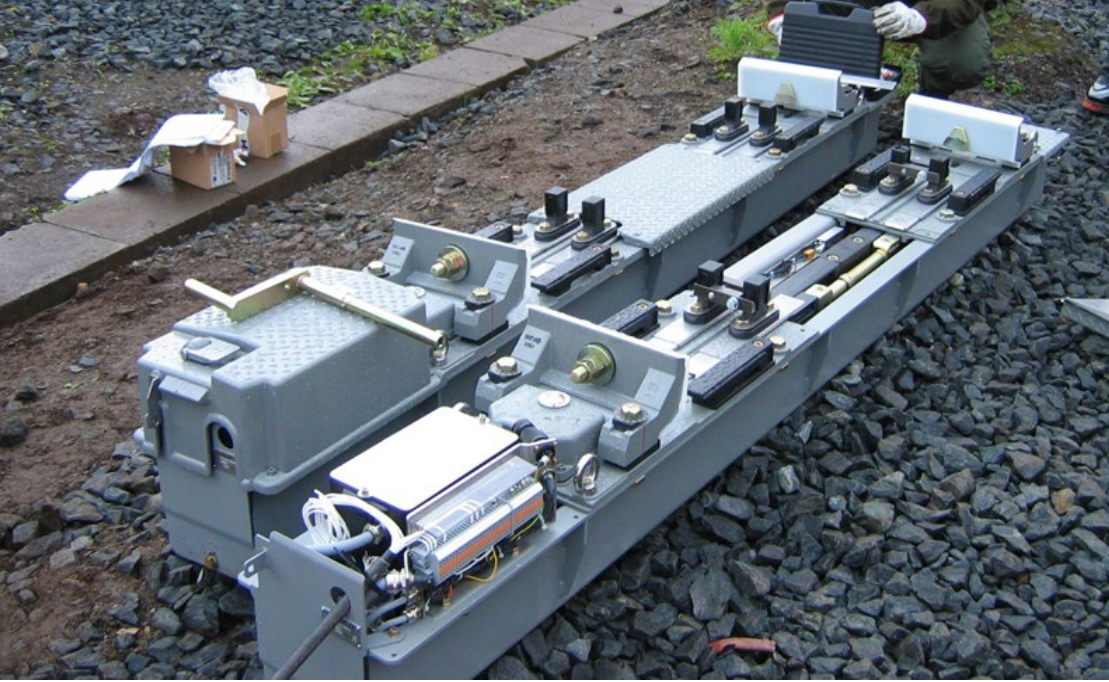
In a sleeper-mounted machine the drive and detection rods are protected inside the sleeper, making drainage important. A modern example is Siemens ITS710, supplied from 400 V three-phase power; a legacy installation can require a TPAM interface. Product compatibility must be checked for the actual installation. Independently of machine type, the required functional sequence is to withdraw detection, unlock, move, lock, prove locking and prove position. See Bane NOR's point-equipment requirements [246].
Flank protection prevents an unauthorised movement from reaching a secured route from the side. It may use signals held at stop or points locked away from the protected route, as well as physical derailing devices. The highlighted objects in Figure 13.30 protect a route against movements from adjoining tracks. Their positions and locking belong to the route's safety conditions even where the authorised train does not run over those objects.
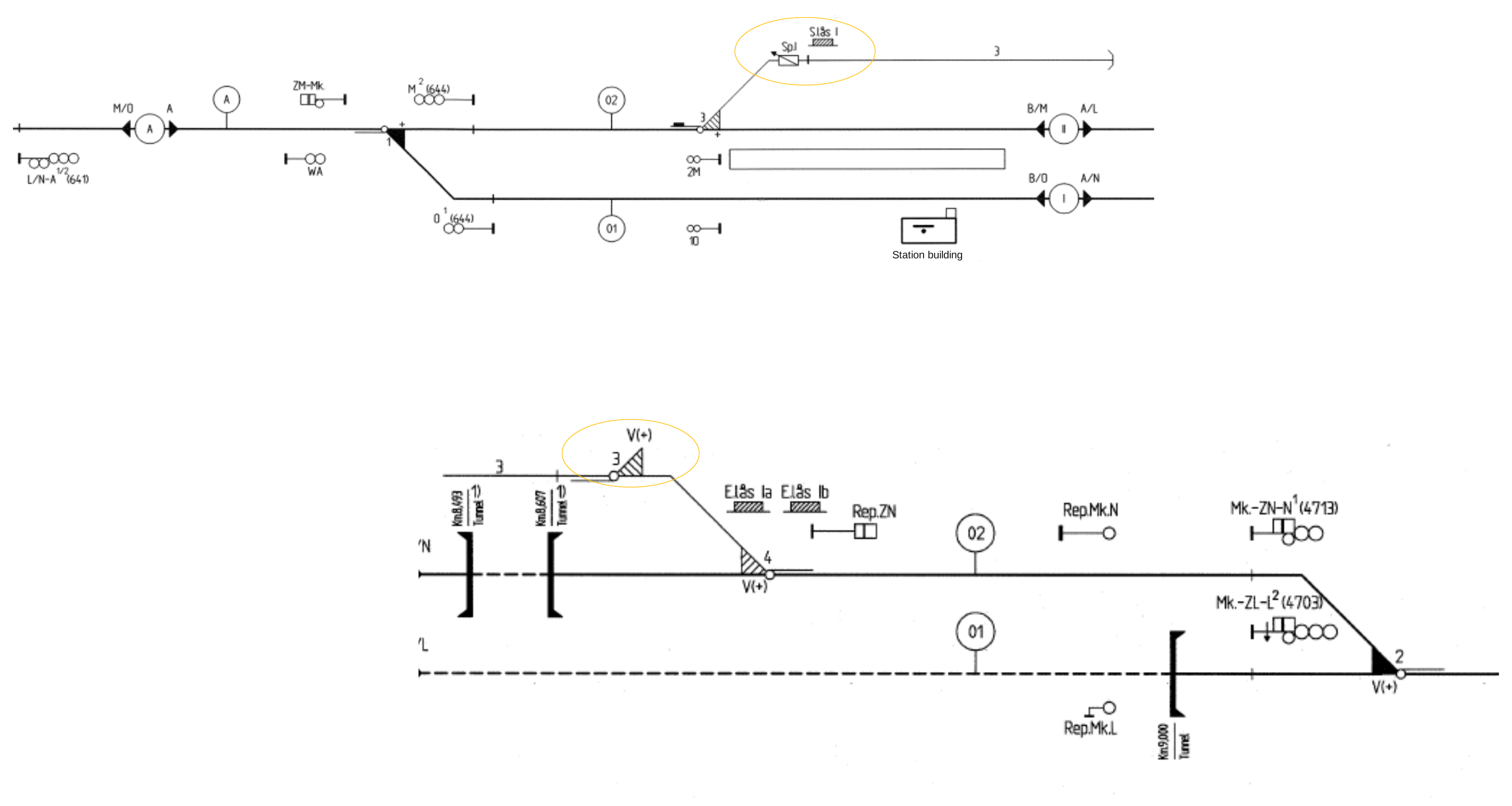
Two examples of physical protection against runaway vehicles from a siding are:
-
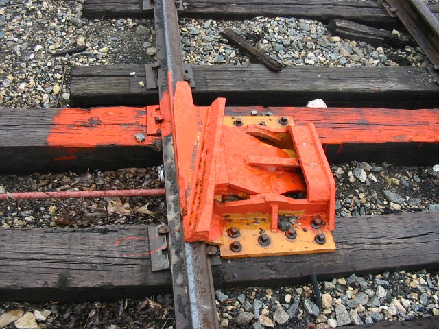
Derailer: a simple device placed on the rail that forces any approaching vehicle off the track before it can enter the protected area. Figure 13.53 shows a rail-mounted example. The 40 km/h limit alone is not sufficient: where the gradient towards the protective object exceeds 2‰, or the speed in the protected area exceeds 40 km/h, Bane NOR requires a turnout or derailing tongues. See TRV:02464 [252].
-
Catch point: a derailing switch that diverts a runaway vehicle away from the protected route. It is more effective than a simple derailer, but requires more space [20].
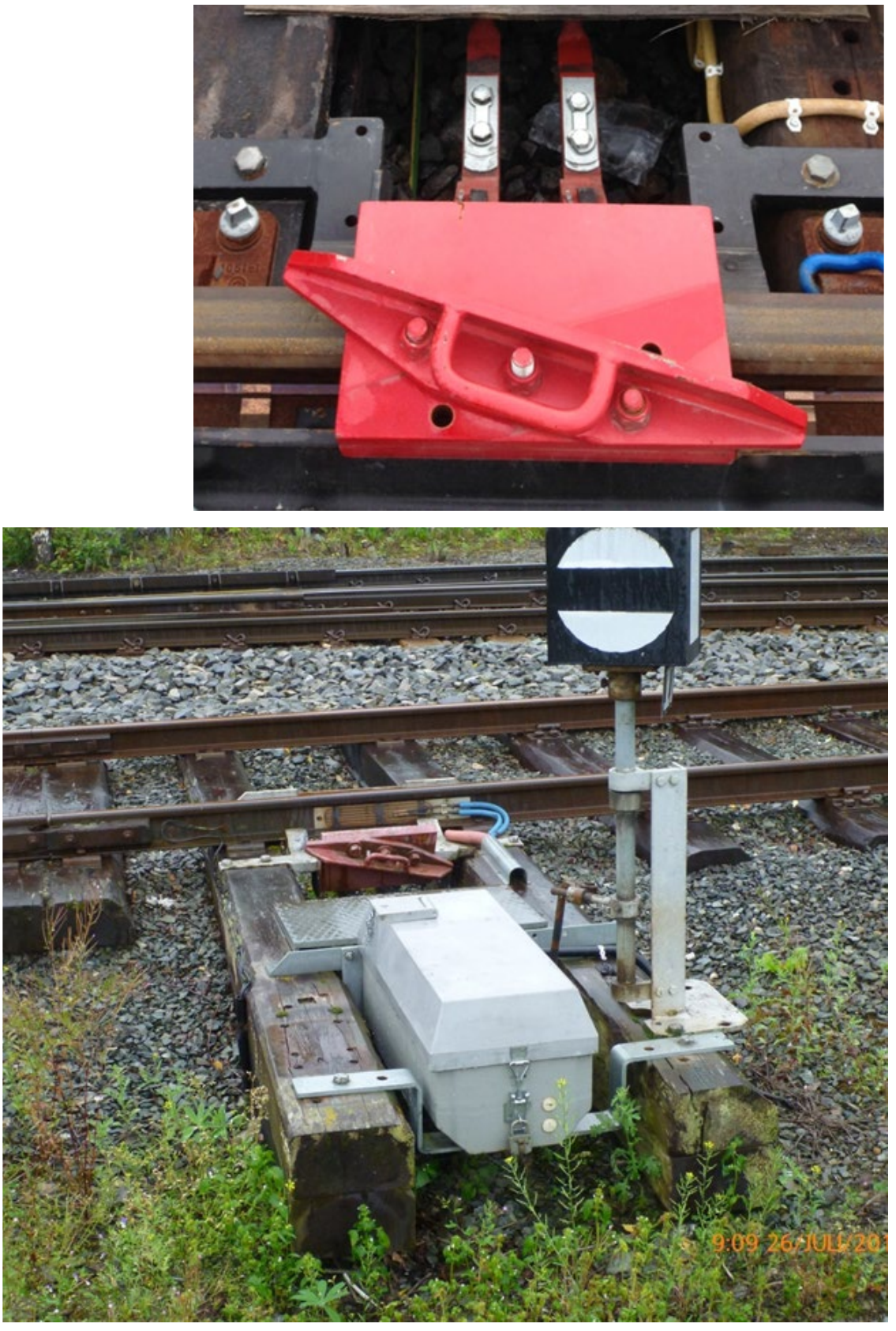
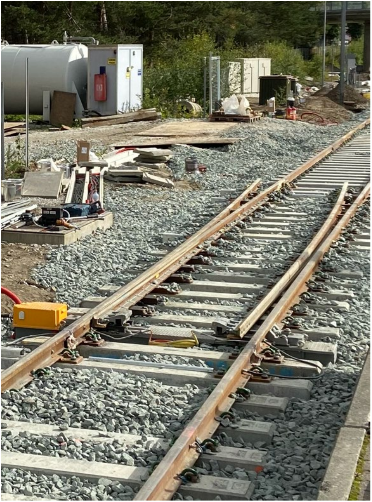
The derailers in Figure 13.31 lift a wheel off its normal running path. The derailing switch tongues in Figure 13.32 instead guide the vehicle away from the protected route. Both deliberately sacrifice the uncontrolled vehicle's normal path to protect other movements. They need suitable space and a design appropriate to the risk and applicable requirements.
13.8 Line Block and Block Posts
A station interlocking secures movements within the station. A line block provides the corresponding protection between stations: a following train must not receive normal authority into an occupied block section, and opposing authorities on the same single track must be prevented. Train detection supplies occupancy information, while block dependencies control the permission to enter.
A block section is bounded by neighbouring stations, neighbouring block posts, or a station and its neighbouring block post. A block post is the boundary between two block sections. These are operational boundaries. A train-detection section is the area monitored by one detection arrangement, and need not be identical to a whole block section. See Bane NOR's operational definitions [248].
Figure 13.33 shows the line between two station layouts. A train travelling from the left station to the right must have its station departure route secured and permission to enter the intervening block section. The protection must remain effective until the train has cleared the section and the release conditions are satisfied.
Adding a block post divides a long section into shorter sections. Two trains travelling in the same direction can then occupy different sections and follow each other more closely. It does not create a place for opposing trains to meet. On a single-track line, crossing opportunities still depend on stations and passing loops, and capacity remains limited by running times, braking distances, route release and the timetable [250].

13.9 Automatic Train Control
Automatic Train Control adds onboard supervision to the lineside signalling system. Its purpose is to reduce the consequences of missed signals or overspeed events.
13.9.1 Principles
Even with a perfectly functioning signal system and a red signal displayed, consequences depend on whether the driver sees and obeys the signal. Automatic Train Protection (ATP) is the safety function that supervises whether the train remains within its permitted speed and movement authority, and intervenes by braking if necessary. In Norway this protection function is provided by Automatic Train Control (ATC), the on-board system that supervises driver compliance with signal and speed information.
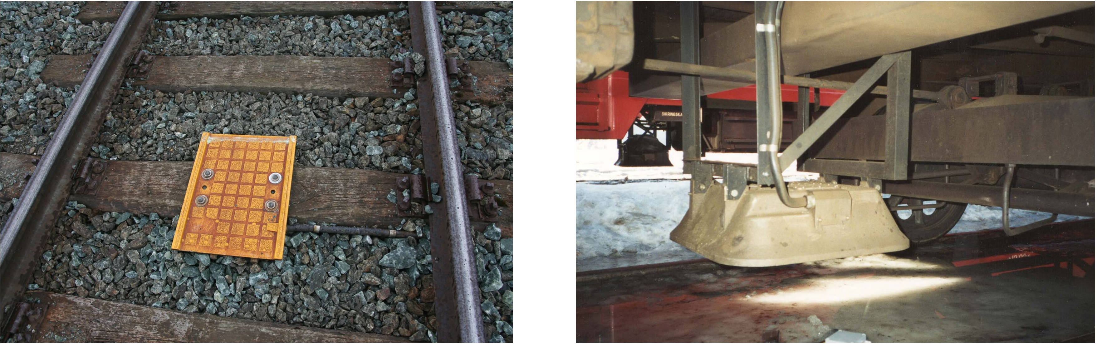
The Norwegian ATC system operates with lineside balises (transponders mounted between the rails). The train's antenna activates a balise as it passes and receives encoded data for the onboard computer. The principle drawing in Figure 13.34 connects the signal and encoder to the balises, antenna, computer and driver's display.
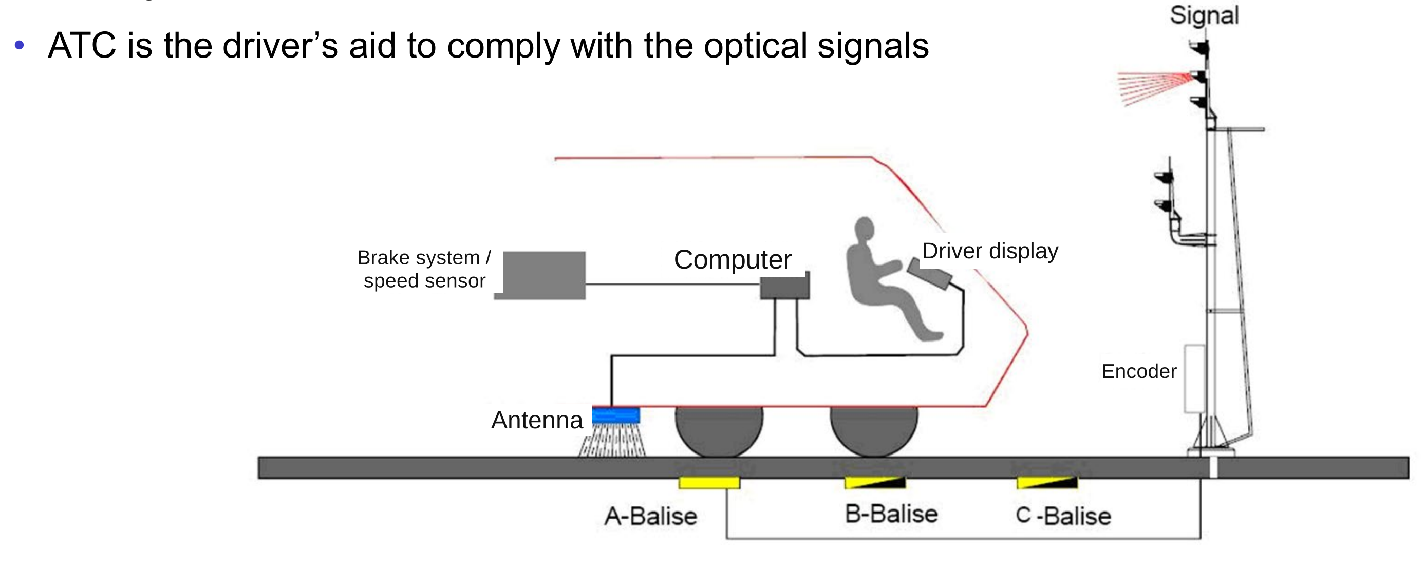
The transmitted information can include the items below. The onboard equipment stores the relevant data and supervises the train after it has passed the transmission point. Figure 13.35 shows the physical balise and antenna interface.
-
Speed limits and signal aspects ahead.
-
Signal-related permission or restriction information for the equipped point.
-
Gradient information for brake curve calculation.
The national ATC cab equipment presents the received speed and signal information and supervises the train against it. If the driver does not respond as required, the system intervenes by braking. Figure 13.36 places the national ATC display in its driving environment and shows the equipment in more detail.
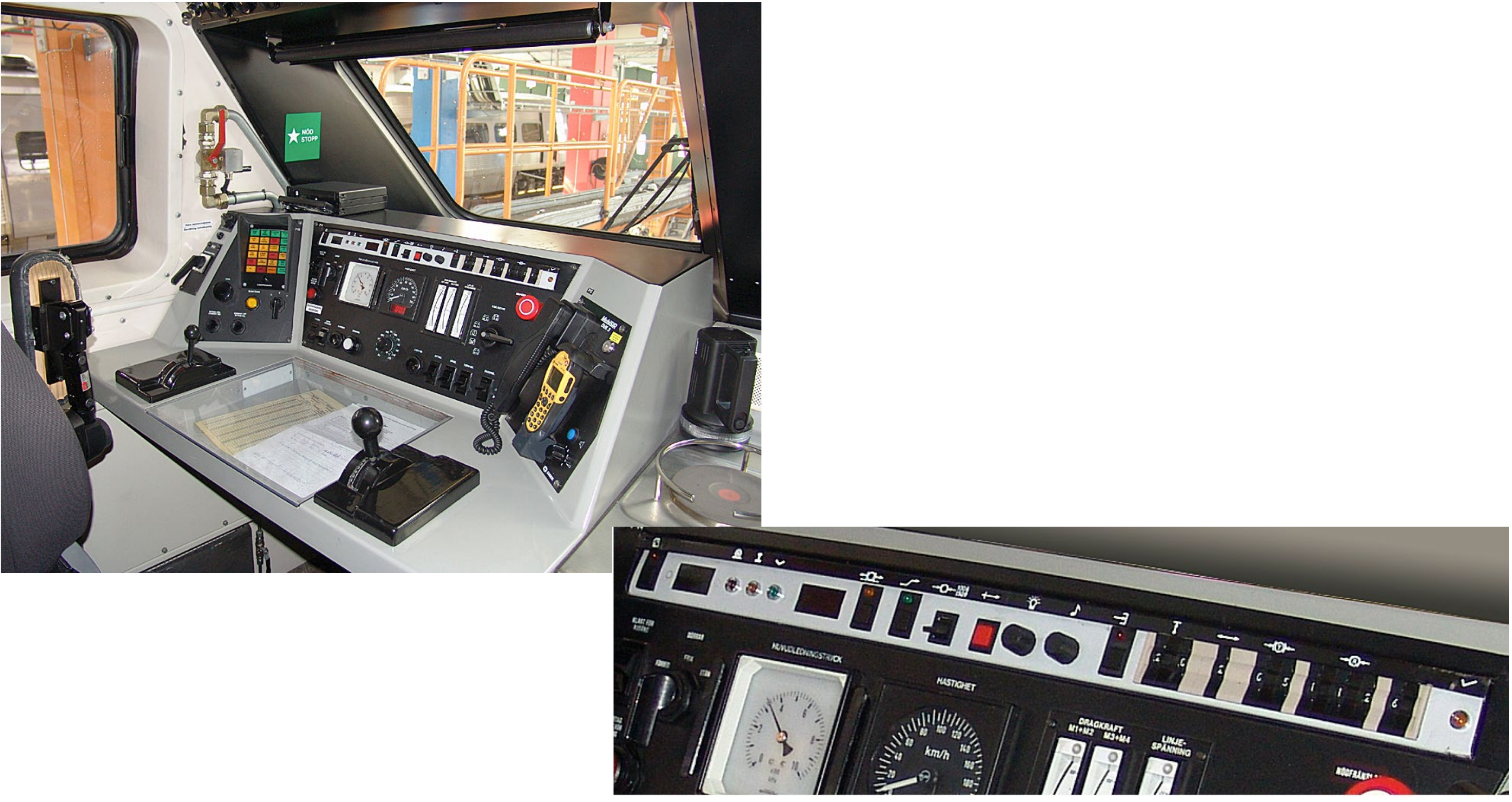
This is distinct from the ETCS Driver Machine Interface (DMI), introduced in the ERTMS section. DATC and FATC describe national ATC supervision, not ETCS levels.
13.9.2 ATC Coverage Levels
ATC coverage levels differ mainly by where balises are installed and how completely signal information and speed restrictions are supervised. Figure 13.37 compares non-equipped, partly equipped and fully equipped national ATC areas through the location of their transmission points. Signal-associated balises provide information at the signals. Additional transmission points support supervision of speed restrictions along the line.
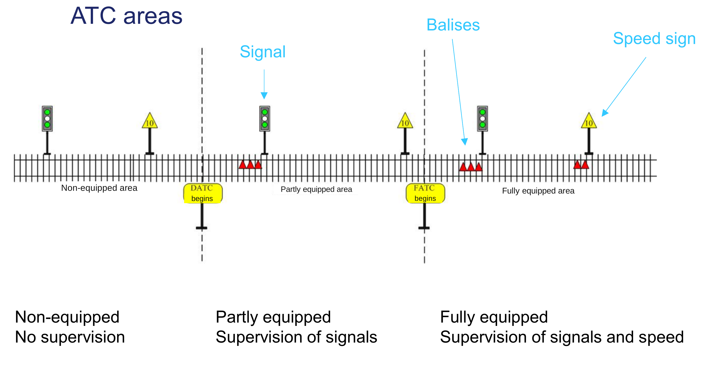
The diagram's “No supervision” label is a teaching simplification: onboard ceiling-speed supervision can remain active without track-transmitted ATC signal information. The partly equipped description is also shorthand. DATC also supervises configured ceiling speeds, specified turnout speeds and temporary restrictions. FATC provides more complete supervision of speed restrictions. These distinctions are set out in the Bane NOR ATC handbook [253]. Table 13.1 retains the comparison with ERTMS for reference, but its final row belongs to the different ETCS system explained next.
| Coverage level | Trackside equipment | Main supervision effect |
|---|---|---|
| Non-equipped | No track-transmitted ATC signal information | Onboard ceiling-speed supervision can remain active, but the driver must observe lineside signals and speed signs. |
| DATC, partly equipped | Balises at main signals and selected control points | Supervises main-signal information and important restrictions, but not every intermediate speed sign. |
| FATC, fully equipped | Balises at signals and speed boards | Supervises both signal aspects and permissible speeds over the equipped line section. |
| ERTMS Level 2 | Balises for position reference plus radio movement authority from the RBC | Cab signalling and continuous brake-curve supervision replace traditional optical signal dependence. |
13.10 ERTMS: European Rail Traffic Management System
ERTMS is introduced here as both a technical renewal programme and an interoperability standard. The need for it follows from the age and fragmentation of legacy signalling systems.
13.10.1 Background
ERTMS is driven by renewal pressure from legacy signalling assets. Norway's legacy signalling systems face a systemic problem:
-
Most systems were installed in the 1970s–1990s and have exceeded their design lifetimes.
-
Spare parts for older relay systems are no longer manufactured.
-
Supplier support has ended for several system types.
-
The technology is no longer taught, so specialist maintenance knowledge is disappearing.
-
The result is increasing fault frequency and fault-correction times, leading to reduced availability and capacity.
A comprehensive renewal of the entire Norwegian signalling infrastructure is therefore necessary [30]. Bane NOR has chosen ERTMS Level 2 as the national standard for this renewal [10].
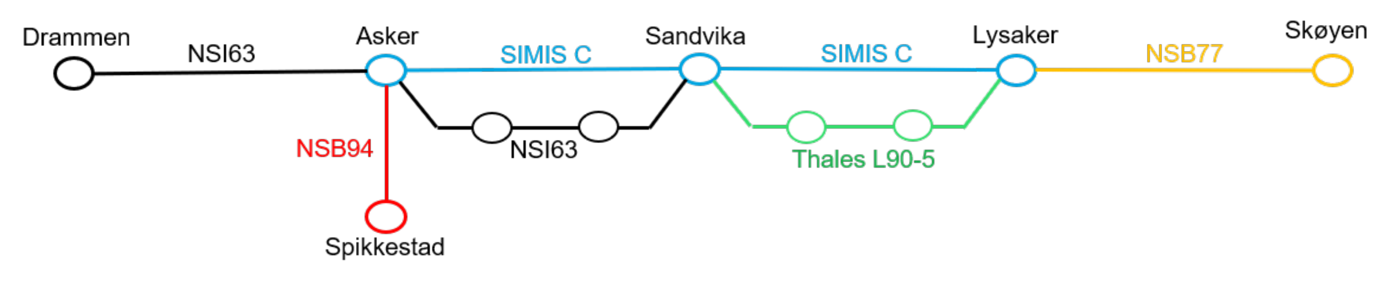
The Drammen–Asker example in Figure 13.38 shows why renewal involves more than replacing old signal heads. Different interlocking generations can occur along one corridor. Their interfaces, spare parts and maintenance competence differ, which makes fault finding and renewal planning more demanding. The diagram records the lecture's example, not a live register of the equipment currently in service.
ERTMS in Norway
The Norwegian rollout should be understood separately from the general level definitions in Table 13.2. Bane NOR has selected ERTMS Level 2 as the national standard for the renewal programme [10], and Norway plans to install ERTMS Level 2 on the entire national railway network [96]. Gjøvikbanen nord and Østfoldbanens Østre linje are the first lines in revenue operation with the new system. The train-integrity-reporting row explains the former Level 3 architecture within the current Level 2 definition. It is not a separate Norwegian rollout target.
13.10.2 ERTMS Architecture
ERTMS (European Rail Traffic Management System) consists of three components:
-
ETCS (European Train Control System): the standardised train protection and control subsystem, covering cab signalling, speed supervision, and movement authorities.
-
Railway Mobile Radio (RMR): GSM-R (Global System for Mobile communications, Railway) carries voice communication and data between trains and the Radio Block Centre (RBC). Its successor, FRMCS (Future Railway Mobile Communication System), is being developed by UIC with railway stakeholders and standardisation bodies, within the ERA/EU interoperability framework. It uses 5G technology to support greater data capacity and new digital functions. GSM-R and FRMCS will coexist during migration. UIC identifies expected GSM-R end of support around 2035; this is a planning horizon, not a confirmed common completion date for every European network. See UIC's FRMCS programme [212].
-
Operational regulations: harmonised rules support interoperable operation across networks. Actual operation still requires compatible onboard and trackside systems, the applicable vehicle authorisation, route compatibility and compliance with operating rules. ERTMS fitment alone does not establish permission to use every fitted line. See the OPE TSI route-compatibility provisions and Appendix D1 [213].
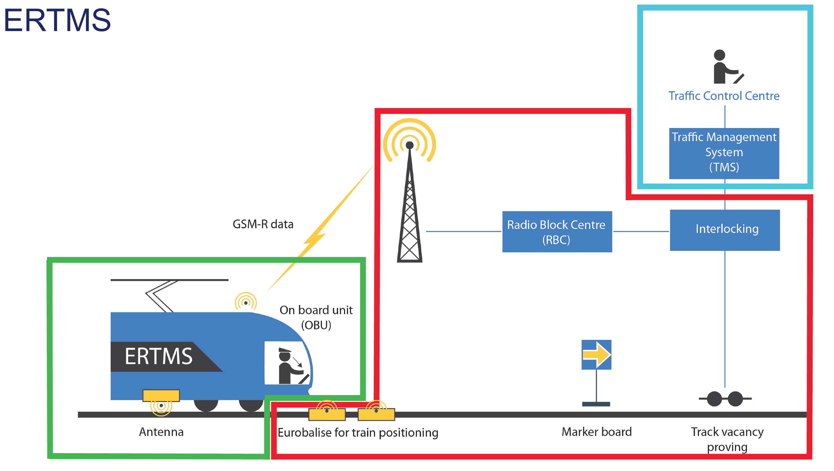
Follow the architecture in Figure 13.39 from the traffic-control centre to the train. Traffic management requests a movement. The interlocking proves the compatible route conditions. The Radio Block Centre uses the relevant interlocking and train information to issue a movement authority by radio to the onboard ETCS equipment. Balises provide fixed position references to correct the train's odometry. Trackside detection still proves the occupancy of the sections used by this Level 2 arrangement. The onboard equipment displays the authority and supervises the permitted movement.
13.10.3 ERTMS Level 2 and Marker Boards
On conventional lines, a lineside signal both gives a visual aspect and marks a physical route boundary. ERTMS Level 2 separates these functions. The movement authority, target speed and braking supervision are handled in the cab, while fixed marker boards remain at the trackside as physical reference points for where an authority may start or end. In the architecture described above, the marker board is not a colour-light signal. It does not display dynamic speed or proceed information. It marks a location used by the interlocking, the Radio Block Centre and the operational rules.
In normal operation, a train may pass an ERTMS stop marker only when the cab display contains a movement authority that permits movement beyond that point. Without such authority, the marker is the physical stop reference. Bane NOR's current rulebook illustrates this with Signal E35 stop markers; the arrow shows which track the marker applies to, as illustrated in Figure 13.40 [56].
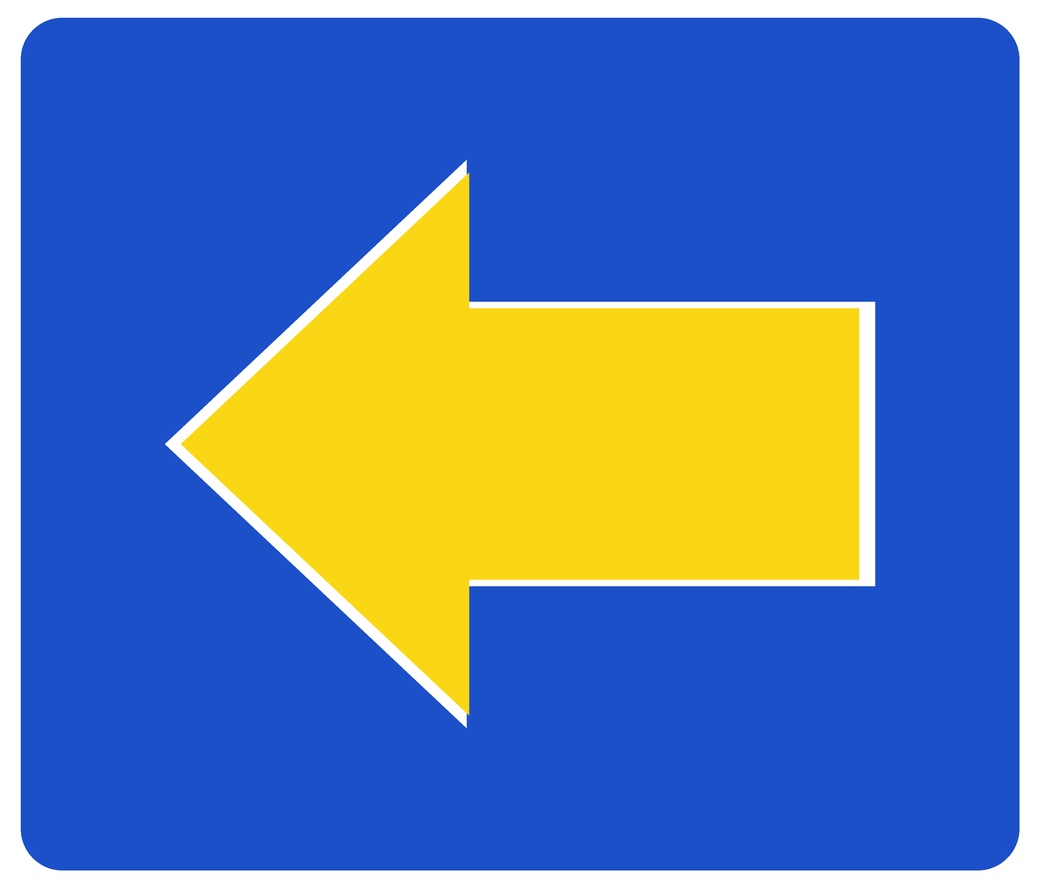
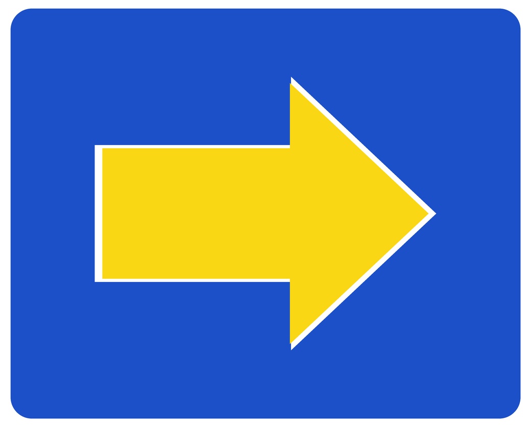
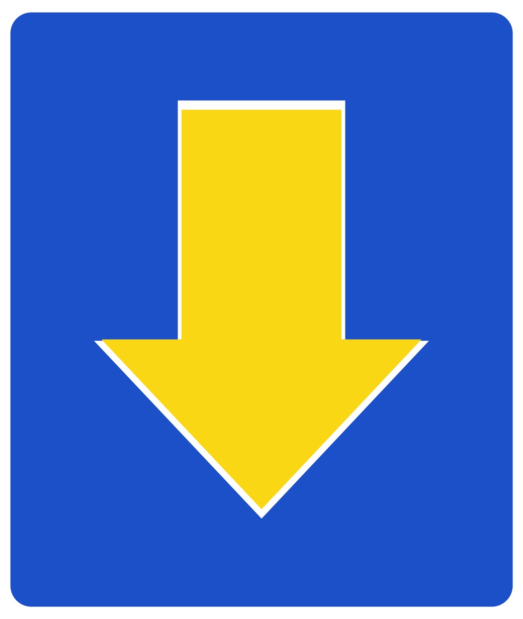
The arrows identify the applicable track: to the left in Figure 13.40(a), to the right in 13.40(b), or below the board in 13.40(c). An arrow is a track identifier, not a proceed indication.
13.10.4 Driver Machine Interface
In ETCS/ERTMS, the driver's cab display is the Driver Machine Interface (DMI): the screen that shows speed, target distance, permitted speed, operating mode and profile information to the driver. Figure 13.41 shows an example of the DMI layout.
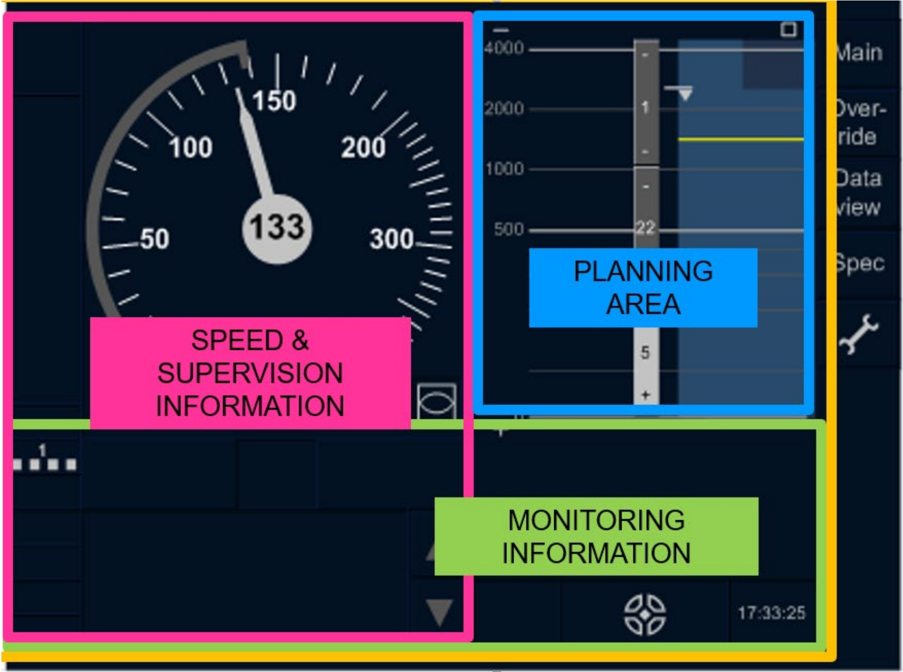
Read the DMI in its functional areas. Speed and supervision information give the current speed and the applicable limits. The planning area shows upcoming targets and profile information. The monitoring area carries operating-mode and other status information. The display brings together what the driver needs to follow the authority, but the ETCS onboard equipment performs the supervision and can intervene by braking.
Balises retain an important role even though Level 2 uses radio: they provide known track positions. Digital signalling also does not eliminate every equipment, power or communication failure. Renewal changes the technology and its diagnostics, while safe degraded operation remains necessary.
13.11 Simultaneous Entry and Safety Distances
On a single-track railway, opposing trains meet at a station or passing/crossing loop with more than one usable track. Whether they may enter together depends on the secured routes and the protection beyond their endpoints. Follow the explanation in this order: fouling point, release speed, safety distance, route endings, simultaneous entry, paired markers, and protective points.
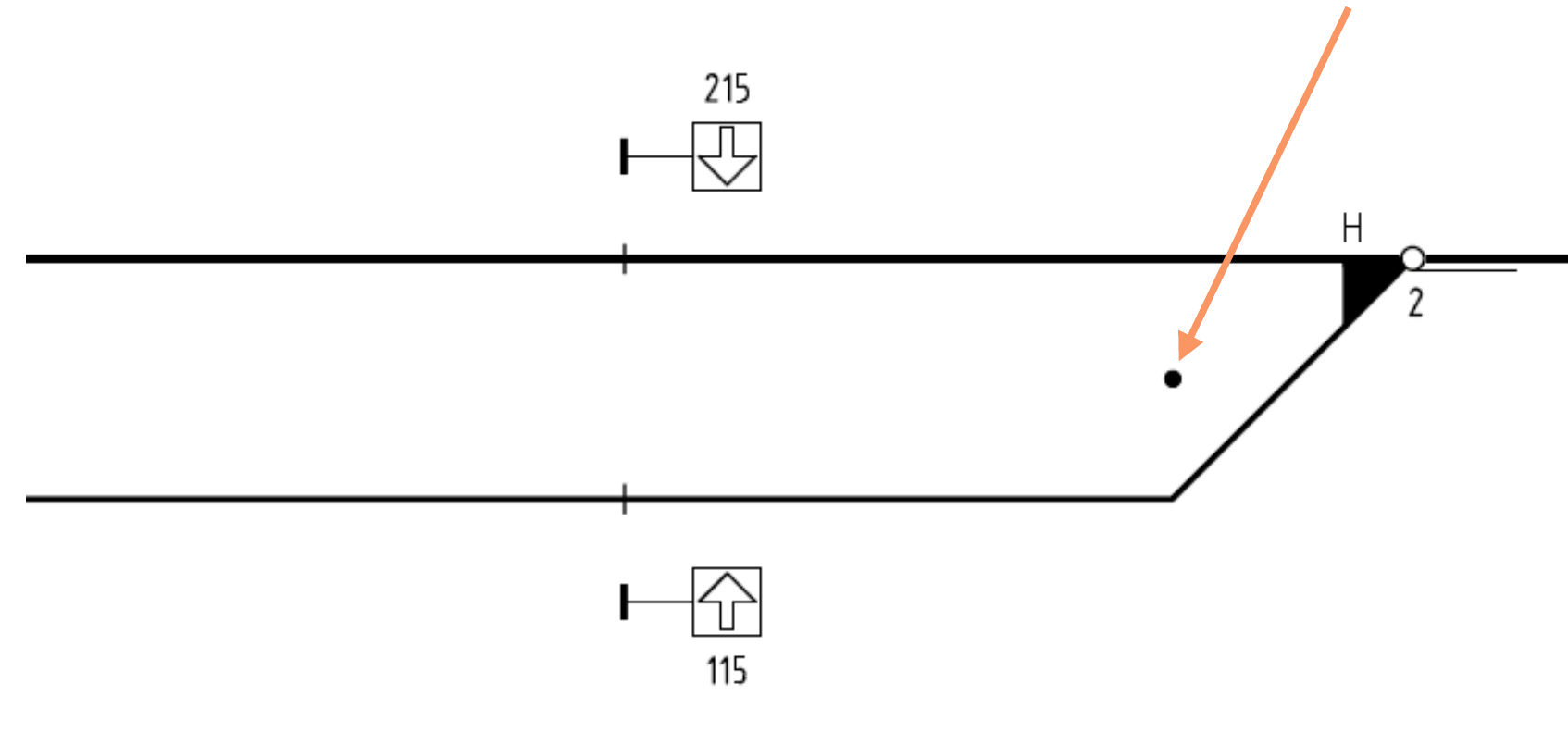
Start with the fouling point. This is the clearance limit near a turnout. A vehicle standing beyond that limit can obstruct the converging track even if its wheels remain on its own rails. In Figure 13.42, the arrow identifies the clearance limit. Protection must account for the whole vehicle envelope, not just the position of the switch blades.
13.11.1 Release Speed and Safety Distance
The next step is to ask how the train approaches the end of its movement authority. ETCS calculates braking supervision towards that endpoint. Close to the endpoint, a specified release speed can allow the train to approach the stopping location without an impractically restrictive final braking curve. It does not give permission to pass the end of authority.
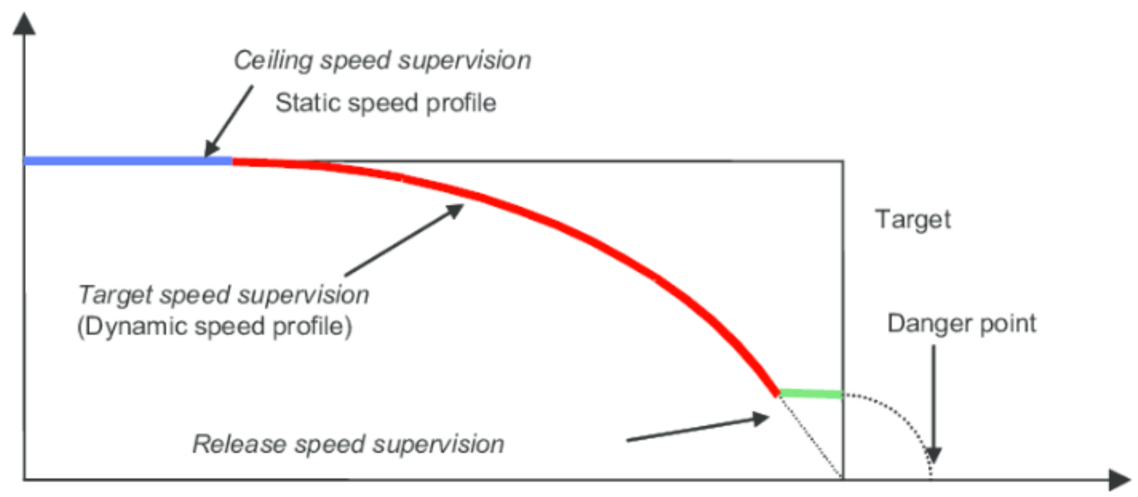
In Figure 13.43, read the speed on the vertical axis and distance along the horizontal axis. The decreasing curve represents target-speed supervision as the train approaches its target. The release-speed region concerns the final approach. The protected distance beyond the endpoint provides separation from a conflicting route or danger point. Its required length depends on the applicable design case.
At the end of every secured train route there is a safety distance: a protected zone that must remain free of conflicting activity. The required distance is a layout- and system-specific design parameter, affected by release speed, braking supervision, overlap philosophy, train detection, route locking and local Bane NOR rules. The release speed is the maximum speed the train is permitted to have when approaching the end of its route. The values in Table 13.3 are sample values used to explain the simultaneous-entry calculation, not universal constants.
The 70 m example corresponds to the Level 2 table entry for 20 km/h release speed towards a flank or opposing route, before gradient correction. The 250 m legacy example likewise applies to a particular station protection case. A real design must apply the table, exceptions and gradient corrections in Bane NOR's interlocking requirements [251].
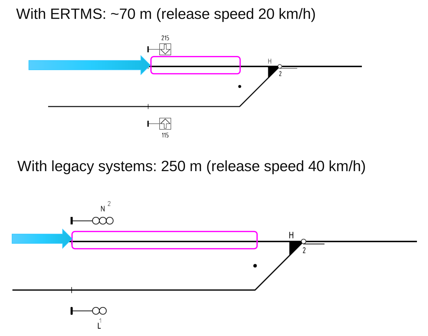
The coloured protected zones in Figure 13.44 should be compared with the fouling point, not simply with the platform end. A zone that extends into the opposing route can prevent concurrent route setting. A shorter required distance can make it possible to end the protected zone before the conflict, but only if the complete interlocking conditions are satisfied.
The supplementary calculation applies these distances to a passing loop and provides the worked example used in Assignment 2.
13.11.2 Capacity Consequence at a Passing Loop
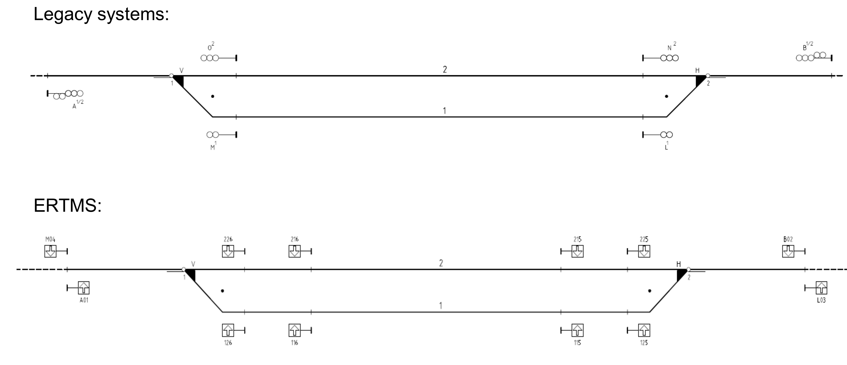
First compare the route-ending objects in Figure 13.45. The legacy layout uses lineside signals. The ERTMS layout uses stop markers linked to cab authority. Their placement determines where the authorised route ends and where its protection begins.
A train route is the defined track portion secured for the movement. In Figure 13.46, follow the highlighted path through the station and identify its start, endpoint and the points used by it. The route is not the whole station, and its endpoint must be distinguished from the additional protected zone beyond it.


The blue and green paths in Figure 13.47 belong to two opposing arrivals on separate tracks. Both routes and their protection must be compatible. This is a different use of colours from the later paired-marker example, where blue and green represent alternative endpoints for one arriving train.
Simultaneous entry means that the interlocking can establish two entry routes from opposite ends of a crossing station together, so one train need not wait for the other to arrive. Figure 13.48 shows two conventional layouts. The upper layout in 13.48(a) retains more usable track length, but its route-end protection extends beyond the fouling points and excludes the opposing entry. The lower layout in 13.48(b) places the route endings farther inside the station so their safety zones fit before the fouling points. Simultaneous entry is then possible, at the cost of usable stopping length. Conventional signalling can therefore also permit simultaneous entry when the layout provides adequate protection. In the ERTMS example, shorter supervised safety zones can retain more useful track length. Each route must be safe individually and together with every concurrently authorised route.
Without simultaneous entry

With simultaneous entry

The shorter design distance in the ERTMS sample arises from supervised braking and release-speed enforcement. The ETCS onboard unit estimates train position from odometry and corrects it at balises, while Level 2 operation still relies on trackside train detection and fixed interlocking logic. Simultaneous entry is therefore a combined property of the marker-board layout, movement authority, release speed, route locking and train-detection design, rather than simply "knowing the exact train position".
13.11.3 Paired Marker Boards
The ERTMS example combines a shorter required safety distance with a choice of route-ending stop markers. A long required distance can instead require more station length, an endpoint farther inside the station, or suitable physical protection. Figure 13.49 shows alternative endpoints for one arriving train. The short route leaves protection before the fouling point for an opposing arrival. The longer route provides more usable stopping length when the conflicting entry is not authorised. Paired markers are a layout solution in this example, not a universal requirement at every ERTMS station.

The blue and green arrows show alternative movement-authority end points for the same arriving train, not two authorities issued to that train at once. The blue, shorter route ends at the inner marker, leaving the required safety distance before the fouling point so an opposing train can enter. The green, longer route ends farther along the same track and gives the arriving train more stopping length, but excludes the conflicting opposing entry.
13.11.4 Trap Points and Directional Operation
Where there is insufficient room for the required safety distance, a trap point can provide physical protection by directing an overrun away from the conflicting route. This adds points, land requirements and maintenance, and the layout must still satisfy the applicable protection requirements. It does not remove the need to prove a safe route.
A layout with such protection may assign one loop track to each normal direction of travel. This directional operation can allow simultaneous entry in the intended arrangement, but reduces flexibility if a train needs to use the other track or equipment is unavailable. The useful comparison is therefore between safety distance, usable track length, crossing capacity and operational flexibility, rather than a claim that ERTMS automatically makes every station suitable for simultaneous entry.
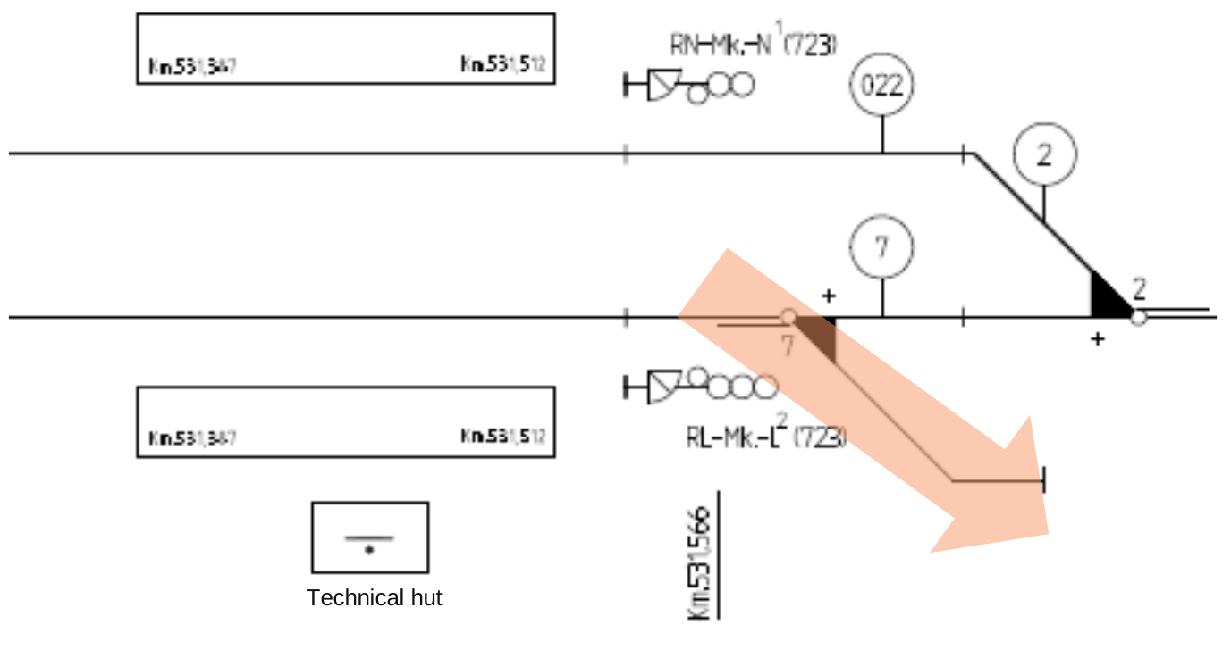
The diverging path in Figure 13.50 directs an uncontrolled overrun away from the route being protected. This changes where space is needed. It does not mean that the overrun has no consequences or that the station needs no protected space.
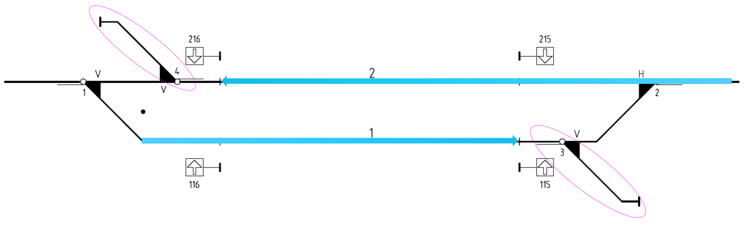
In Figure 13.51, follow each blue arrival path to its stopping position and the protection beyond it. Using one track for each normal direction can make the intended pair of arrivals compatible. The price is reduced freedom to choose the other track. The layout must also accommodate train length, platforms and the movements needed during faults or maintenance.
13.12 Supplementary Material
Supplementary reference: ETCS levels
The principal ETCS levels are summarised in Table 13.2. This is a conceptual overview of how movement authority and train supervision change from conventional signalling toward cab signalling and moving-block operation. CCS TSI 2023 merged the former Levels 2 and 3 into an expanded Level 2 definition. The table retains the architectural distinction to explain train detection and integrity; “former Level 3” is therefore a historical architecture label. The EU CCS TSI consolidated on 5 May 2026 [74], Section 7.2.9.1, retains this distinction within Level 2. Norway’s TSI CCS Regulation implements Regulation (EU) 2023/1695 from 15 March 2025 [214]; the later EU consolidation date does not itself establish Norwegian legal effect.
| Level | Authority path | Lineside signals | Train detection and integrity |
|---|---|---|---|
| Level 0 | No ETCS movement authority; national operating rules apply | Depends on the line equipment | ETCS-equipped train on a line without ETCS. Limited onboard supervision applies, rather than full movement-authority supervision. |
| Level NTC (formerly STM) | National train-protection system | Depends on the national system | National train protection is used through a compatible onboard interface. |
| Level 1 | Signal \(\rightarrow\) Eurobalise \(\rightarrow\) cab | Normally retained | Trackside systems prove train location and train completeness. |
| Level 2 with trackside train detection | RBC \(\xrightarrow{\text{radio}}\) cab; balises correct position | Optional; authority is shown on the DMI | Trackside train detection remains part of the authority calculation. |
| Level 2 with train integrity reporting (former Level 3) | RBC \(\xrightarrow{\text{radio}}\) cab + train integrity report | Not needed for movement authority | The train reports its own integrity, enabling moving-block operation. |
ERTMS changes both the driver's information source and the way movement authority is enforced, especially when moving from lineside signals to continuous radio supervision.
Supplementary calculation: simultaneous entry
For the simplified capacity check used here, compare the distance available from the route-ending object (signal or marker board) to the nearest fouling point with the required safety distance:
If the inequality is satisfied at both ends of the loop, the protected zones can stop before the fouling points and simultaneous entry is geometrically possible. If the required safety distance is longer than the available distance, the protected zone passes the fouling point and the opposite entry route cannot be set at the same time. The useful design margin is \(d_{\text{available}}-d_{\text{safety}}\).
| System | Protection assumption used here | Operational effect at a passing loop |
|---|---|---|
| Legacy interlocking | Lineside signal and overlap; sample 40 km/h release speed and 250 m safety distance. | Long envelopes can overlap around the fouling point. The interlocking may permit only one entry route, so the other train waits outside the station. |
| ERTMS Level 2 | Marker board and cab authority; sample 20 km/h release speed and 70 m safety distance. | Shorter supervised envelopes can fit before the fouling points. Both entry routes can be clear at once. |
Worked example: checking simultaneous entry.
Assume that a candidate route-ending marker board is 95 m before the fouling point at one end of a passing loop. With the sample ERTMS Level 2 safety distance of 70 m, the margin is
The margin is positive, so the protected zone can stop before the fouling point at this end. If the same layout were checked with the sample legacy safety distance of 250 m, the margin would be
The negative margin means that the protected zone would pass the fouling point, so the opposite entry route could not be set at the same time. For a complete station check, the same calculation must be satisfied at both ends of the loop.
Maintenance
The lecture sequence ends with directional operation. The following maintenance discussion is retained as supplementary reading.
Modern signalling components increasingly incorporate sensors that record operational data continuously. Point machines can log force-versus-travel curves for each operation; deviations from the normal signature indicate a developing fault before it causes a signal failure. Track circuits generate voltage and current data that reveal degrading insulated joints or rail contamination.
By combining these data streams with machine-learning algorithms (Bane NOR has cooperated with Microsoft on such systems), the maintenance philosophy can transition from time-based (replace every \(n\) years) to condition-based (replace when the degradation trend predicts imminent failure) and ultimately to predictive maintenance (replace before the fault propagates to a service disruption). This approach reduces both maintenance costs and the frequency of operationally disruptive signal failures.
Supplementary equipment examples
For a published example of the Oslo-area traffic-control centre, see the Elmagasinet report [67].
Figure 13.52 brings the detection chain together: the trackside heads register axle passage, the evaluator combines the boundary counts, and the resulting section state is supplied to the signalling system. Compare these interfaces with the individual components in Figures 13.24 and 13.27.
13.13 Chapter Summary
Movement authority. Trains cannot stop within sight distance like road vehicles, so train movement must be controlled by signals, movement authorities, route locking and train detection. The signalling system must prevent conflicting movements while still releasing capacity as soon as it is safe to do so. Safety and efficiency are therefore handled by the same technical system.
Interlocking. The interlocking verifies that track sections are free, points are correctly positioned and locked, conflicting signals are at stop, and the required safety zone beyond the route is protected. Only then can a signal display a proceed aspect or a movement authority be issued. Mechanical, relay-based and electronic interlockings implement this logic differently, but the fail-safe principle is the same: uncertainty must lead to the safe state.
Train detection. Track circuits detect trains by electrical shunting of the rails, while axle counters count axles entering and leaving a section. Each method has advantages and limitations: some track-circuit designs require insulated rail joints, and train shunting can be affected by poor electrical contact, while axle counters require reset procedures and do not inherently detect vehicles that bypass the counting logic. Detection quality is therefore central to both safety and availability.
Protection distances. Braking distance, overlap, safety distance, route release, simultaneous entry and flank protection determine both safety and station capacity. Long safety distances can reduce usable platform or loop length. At passing loops, simultaneous entry preserves capacity by allowing opposing trains to enter together.
ERTMS. Norway's transition to ERTMS responds to ageing legacy equipment, spare-part shortages, declining specialist knowledge and the need for standardised train control. ERTMS changes how movement authority is transmitted and supervised, especially at Level 2 where cab signalling and radio communication replace conventional lineside signals. The change is technical, operational and organisational at the same time.
Assignments
Assignment 1: Fail-safe principle and interlocking
The interlocking must guarantee that conflicting routes are never simultaneously set. Answer the following questions about the fail-safe principle:
(a) If a signal lamp fails, which safe state must the system ensure? Explain why fail-safe behaviour does not necessarily mean that a red lamp is illuminated.
(b) If a track circuit detects a broken rail or a failed receiver, should the section be reported as occupied or free? Explain why this is the safer output.
(c) For a set of points, what is meant by the normal position? What should happen if the point machine loses power during route setting?
(d) Use the route-setting rule from the chapter: a signal may clear only when the track is clear, the required points are proven, and no conflicting route is set. Complete the table by writing whether the signal may clear in each case. Here, points proven means that the points are locked and detected in the required position.
| Case | Track clear? | Points proven? | No conflict? | Signal may clear? |
|---|---|---|---|---|
| All required checks true | yes | yes | yes | |
| Train detected in the route | no | yes | yes | |
| Point position not proven | yes | no | yes | |
| Conflicting route already set | yes | yes | no |
For each "no" case, explain briefly why clearing the signal would be unsafe.
Assignment 2: ERTMS safety distance and simultaneous entry
At a passing loop (a short double-track section on a single-track main line), the usable track length is 750 m. The fouling point at each end of the loop is located 120 m from the nearest possible marker board (or signal) position (i.e. the available distance from the marker board position to the fouling point is 120 m at each end). Use the route-end check and worked example from Section 13.11.1: compare \(d_{\text{available}}\) with \(d_{\text{safety}}\), and calculate the margin \(d_{\text{available}}-d_{\text{safety}}\).
(a) For the sample legacy case, use \(d_{\text{safety}}=250\,\mathrm{m}\). Is simultaneous entry geometrically possible with this station layout? Show the margin and state why or why not.
(b) For the sample ERTMS Level 2 case, use \(d_{\text{safety}}=70\,\mathrm{m}\). Is simultaneous entry geometrically possible? Show the margin and state why or why not.
(c) Based on the two margins, explain qualitatively why the shorter supervised safety distance in the ERTMS sample enables simultaneous entry at stations where legacy signalling cannot, and why this is especially important on a single-track line with high traffic.
Assignment 3: ERTMS levels and lineside signals
Compare ETCS Level 1 and the two Level 2 architectures in Table 13.2, using trackside train detection or train integrity reporting (former Level 3), with respect to: (i) whether lineside signals are required; (ii) how movement authorities are transmitted to the train; (iii) how train position/integrity is determined; and (iv) which level is being deployed on the Norwegian national network and why. Present your comparison as a table with one row for each ETCS level and columns for the four comparison points.