Continuously Welded Track
In this chapter
11.1 Introduction
The development of continuously welded rail (CWR) in track represents one of the most significant advances in railway engineering [68, 164]. In older conventional track, rails were normally installed as short bolted lengths, typically 10–40 m, connected by fishplates and bolts. From the Stockton–Darlington Railway of 1825 until World War II, jointed track was the normal form of main-line railway track.
Figure 11.1(a) introduces the early railway setting, 11.1(b) the separately supported fishbelly rail and 11.1(c) the bolted joint. Together they show the transition from supporting individual rails to connecting rail ends, which precedes the continuous welded system.
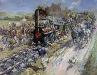
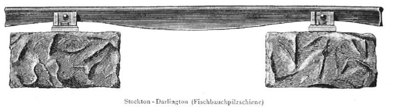
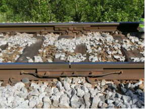
The historical illustration shows a fishbelly rail, whose depth varies between its supports, resting on stone blocks. Material and length depend on the particular early rail design. The Science Museum Group’s Stockton–Darlington-pattern example [176] is wrought iron. Its separately documented 4.5 m fishbelly rail [177] is also wrought iron and comes from the Leicester–Swannington Railway. The lecture’s combined “cast iron, 4.5 m” label should therefore not be treated as a verified specification of the illustrated rail.
The disadvantages of jointed track are significant:
-
Impact loads on the track at every joint, causing accelerated wear and fatigue on both track and rolling stock
-
The need for regular gap adjustment (to accommodate seasonal rail length changes)
-
Noise and vibration from trains crossing joints
-
Reduced passenger comfort
-
Wear on track components, rolling stock, and structures
-
Need for lubrication and inspection of joint bars
From 1945, CWR track began to replace jointed track. Today it is widely used on main lines in Europe and elsewhere [130, 12].
11.2 Track with Continuously Welded Rails
11.2.1 Definition and the Track Panel
CWR track is defined as track where:
-
the rail length is so long that the central part of the rail cannot relieve temperature-induced stress by longitudinal movement
-
the free expansion and contraction that would occur in an unrestrained rail is largely prevented by the track panel, fastenings, and ballast
Per Norwegian regulations, a track with rails longer than 50 m must be treated and maintained as CWR track [12].
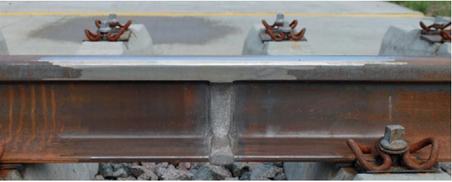
The joint in Figure 11.2 makes the running rail continuous across the weld. Removing the ordinary expansion gap changes the thermal problem from joint movement to the force and restraint behaviour developed in this chapter.
The resistance to longitudinal rail movement in CWR is provided by the track panel, the combined structural frame of rails and sleepers acting together. Three levels of longitudinal resistance act on the rail: fastening clamping force, friction between the rail foot and pad, and sleeper–ballast resistance. Figure 11.3 separates these three restraint mechanisms into \(P_1\) from the fastening, \(P_2\) from friction between the rail foot and pad, and \(P_3\) from the sleeper–ballast interface.
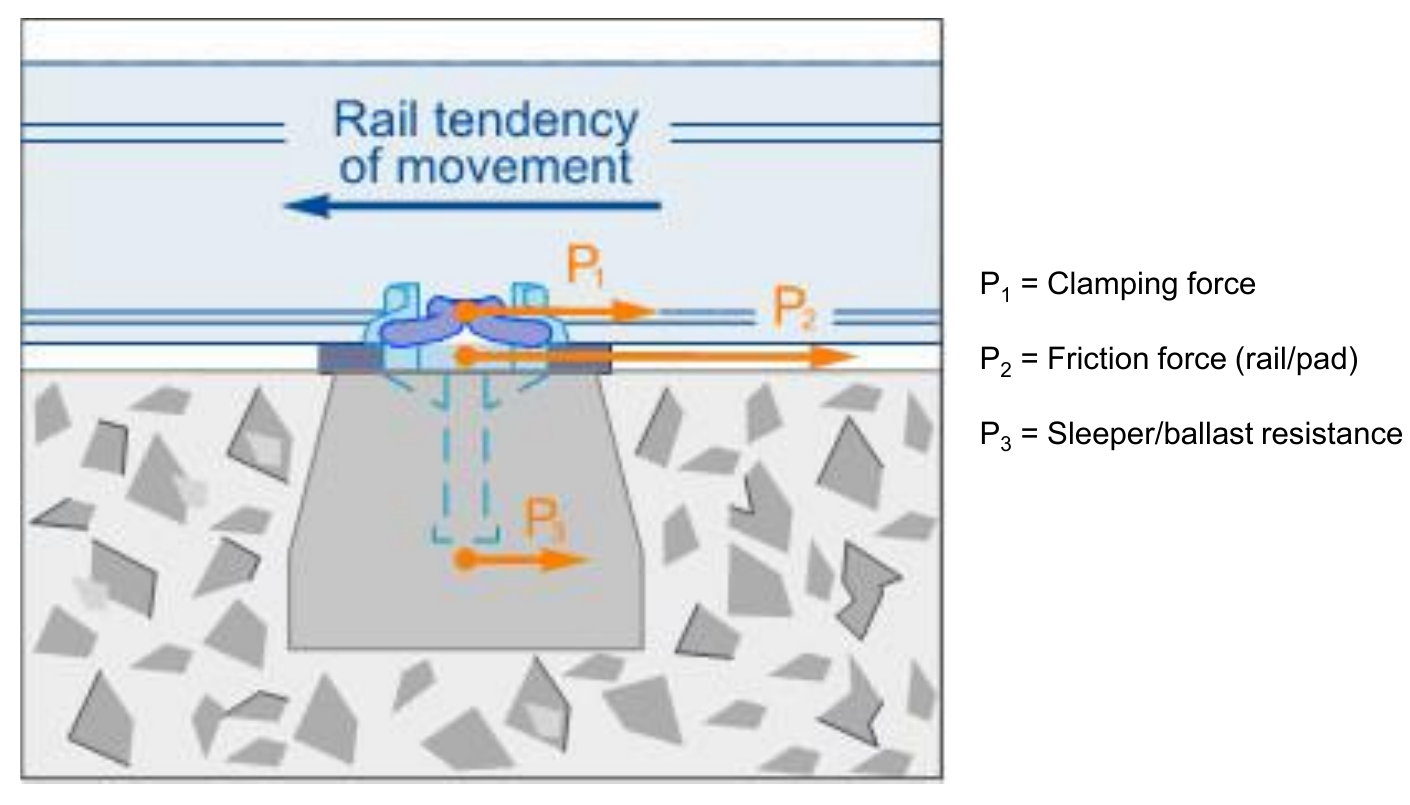
Clamping force presses the rail against the rail pad, allowing friction to resist longitudinal slip. The fastening transfers this action to the sleeper, and the sleeper transfers it to the ballast. These are successive parts of a load path, not three independent axial forces that can simply be added. Slip at a weak interface can limit the restraint of the whole system.
11.2.2 Welding Methods
The lecture distinguishes three processes, with different purposes [175]:
- Aluminothermic welding uses the reaction between aluminium and iron oxide to produce molten steel. It is used for field joints and closure welds where a welding machine may be impractical.
- Flash-butt welding uses electrical heating and upsetting to join rail ends. It can be carried out in a stationary welding plant or with a mobile machine in the track.
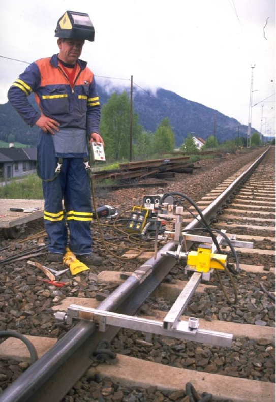
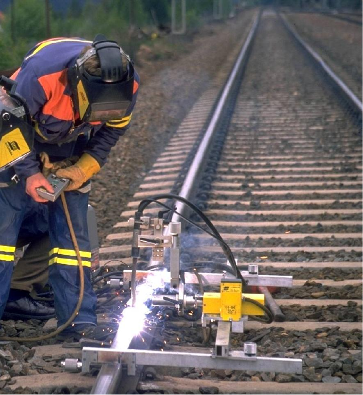
- Electric arc welding is used for approved repair and build-up work on rail heads and turnout components. In this context it is a maintenance process, rather than the usual method of forming a long welded rail string.
The lecture gives an indicative 15-minute duration for aluminothermic welding but does not define the timed stage. It is not a complete field-work cycle or a reopening criterion. Preparation, preheating, pouring, trimming, cooling, finishing and release must follow the approved welding process and applicable work procedure.
Producing a sound weld and setting the correct stress-free rail length are separate tasks. A weld may be metallurgically acceptable while the surrounding track still has an incorrect stress-free temperature. Section 11.3.5 explains the second task; Chapter 2 covers rail components and welding in more detail.
The pour in Figure 11.4(a) forms the closure weld; 11.4(b) shows the joint after trimming and grinding. Distinguish the welding operation from the finished running surface: the latter still requires the specified acceptance inspection.
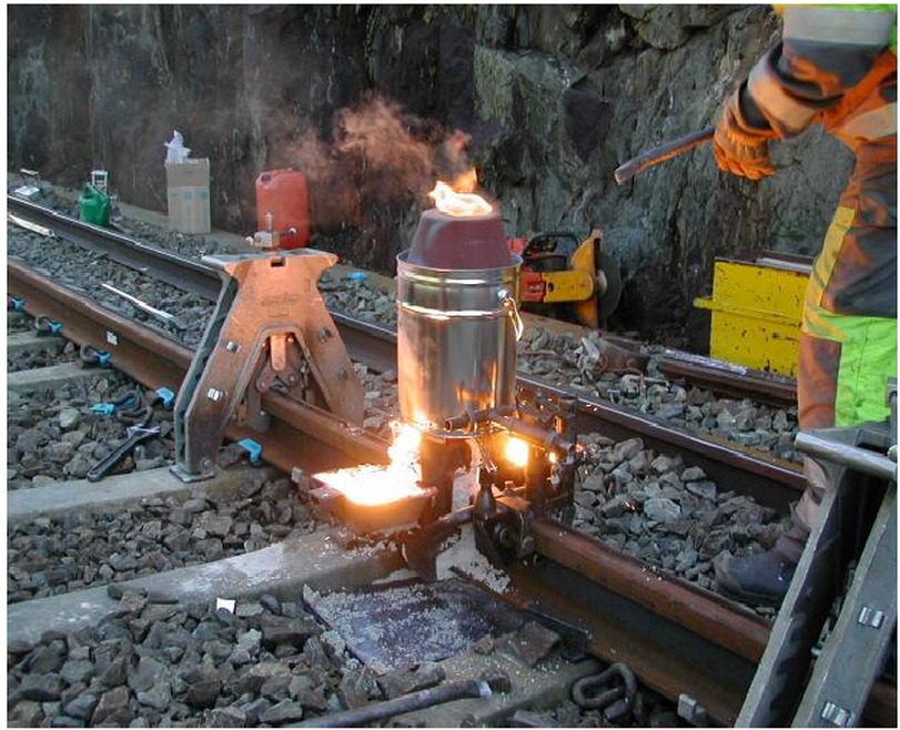 Thermite crucible and mould during the closure-weld pour.
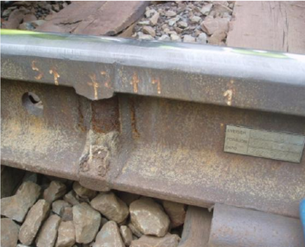 Finished metallurgical weld after trimming and grinding.
The stationary equipment in Figure 11.5(a) and mobile equipment in 11.5(b) apply the flash-butt principle in different production settings. The distinction matters for access and logistics, not for treating one photograph as evidence of weld quality.
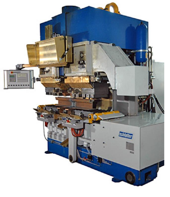
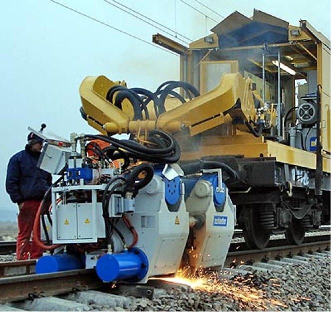
Figure 11.6(a) shows the working setup and 11.6(b) the local rail-head repair. This build-up operation differs from joining two rail ends and must not be confused with a CWR closure weld.
11.2.3 Advantages of CWR
CWR track offers significant operational and economic advantages over jointed track:
-
Reduced track maintenance costs (no joint maintenance)
-
Fewer rail defects and failures (no joint-induced fatigue cracks)
-
Extended rail lifetime (no bolted joints)
-
Reduced wear on superstructure, substructure, and rolling stock
-
Improved riding comfort
-
Reduced noise and vibration emissions
-
Lower energy costs for traction
-
Easier mechanisation of track installation and maintenance
The overall result is a reduced Life Cycle Cost (LCC) compared to jointed track. CWR requires careful control of thermal forces to manage track buckling (sun kink) in summer and rail fracture in winter. These failures can also occur in jointed track [68, 164].
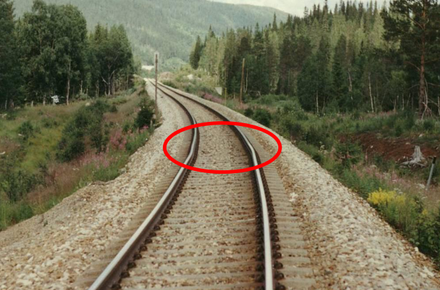
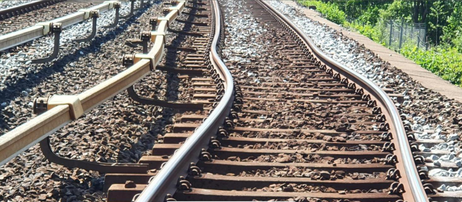
The curve displacement in Figure 11.7(a), the marked local defect in 11.7(b) and the severe distortion in 11.7(c) show different visible extents of lost lateral stability. Use them to recognise geometry requiring investigation, not to infer a stress-free temperature from appearance.
11.2.4 What Makes CWR Possible?
A stable CWR track combines adequate rail and fastening stiffness with sleeper restraint, a suitable ballast profile and a controlled stress-free rail length. A larger rail section, effective resilient fastenings, suitable sleepers and closer sleeper spacing can strengthen the system. None of these removes the thermal force; they help the track resist it. The component mechanisms are developed in Section 11.4.
11.2.5 Permanent Track-Position References
Surveying the alignment. Permanent track-position references allow the position after lining to be compared with the established alignment. Conventional permanent track-position referencing (VUL) and geodetic permanent track-position referencing (G-VUL) provide an external reference for this check. In CWR, the check can detect a change in rail-path length that a short-chord geometry check alone may miss. A smooth-looking curve can still have moved inwards over a long distance. The lecture illustrates both reference-mark surveying and geodetic track-position surveying [175]. The current requirements for surveying, tolerances and any resulting neutralisation must be checked before the work is accepted.
Figure 11.8(a) relates track position to stable external marks; 11.8(b) places it in a surveyed reference system. Both allow a later track shift to be distinguished from movement of an unstable local reference.
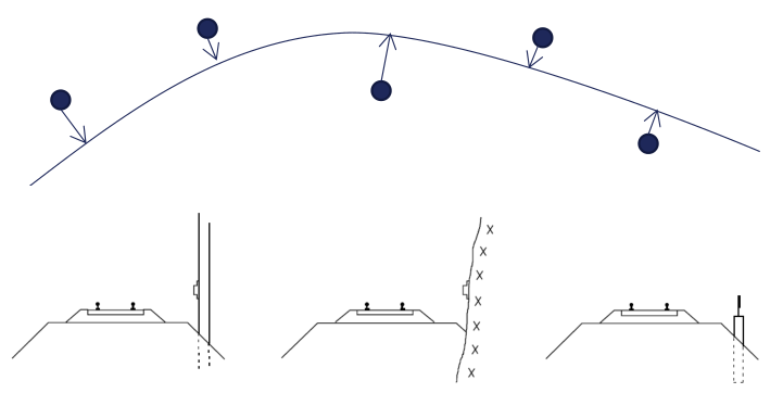
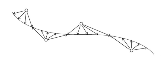
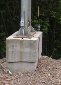
The mark on the foundation in Figure 11.9 is a reference outside the track frame. Its usefulness depends on a stable, documented relationship to the track, not simply on the mark being close to the rail.
The lecture’s VUL table illustrates closer reference-mark spacing in sharper curves. These are recommended distances, not track-position acceptance tolerances. The radius bands below retain the source notation, which does not assign an exact boundary value to one of two adjoining rows. The applicable surveying method and project provisions must be checked in the current VUL/G-VUL rules [178].
| Radius band as printed [m] | Recommended mark spacing [m] |
|---|---|
| –200 | 30 |
| 200–300 | 35 |
| 300–400 | 40 |
| 400–500 | 45 |
| 500–600 | 50 |
| 600–700 | 55 |
| 700–2000 | 60 |
| 2000– | 100 |
11.2.6 Requirements for CWR
The following selected Bane NOR requirements concern CWR in main tracks and main through tracks at stations (hovedspor and hovedtogspor). Separate provisions apply to sidings and shunting tracks. The full regulations also govern component selection, welding and transitions between track constructions [12, 6]:
-
Stable support: As an engineering prerequisite, drainage and frost protection must control support movements that could impair the track geometry or restraint. This is not a separate numerical acceptance criterion for CWR
-
Curve radius in main tracks and main through tracks at stations (TRV:03357–03358, TRV:07977): \(R \geq 300\) m with wooden sleepers; \(R \geq 250\) m with concrete sleepers; \(R \geq 190\) m with BNF54/BNF60 friction sleepers
-
Ballast: Crushed stone, nominal grading 31.5–63 mm in main tracks and main through tracks at stations; Ofotbanen uses 22.4–50 mm (TRV:08262). The prescribed shoulder, crib filling and ballast height are part of the requirement, not optional additions
-
Sleepers and spacing: Concrete sleepers or timber sleepers of type X (TRV:03361); maximum 650 mm in tangent track and curves with \(R \geq 500\) m; maximum 600 mm in curves with \(R < 500\) m; maximum 600 mm for new construction and renewal (TRV:03362–03364)
-
Rail fastenings: Resilient systems with high, durable longitudinal resistance and high torsional stiffness; all fastenings must have friction-enhancing pads between rail and support (TRV:03365–03367). The permitted systems and the separate bridge provisions must be followed
-
Rails: Without visible defects, cracking or burned fishplate holes (TRV:03370)
-
Insulated joints: Type S glued joints or Exel friction joints for permanent installation (TRV:02665); Benkler is permitted temporarily (TRV:02666). See current component rules [49].
-
Turnouts: Must be welded and neutralised according to the turnout procedure, with special control of switch-rail/stock-rail longitudinal position
-
Geodetic permanent track-position referencing (G-VUL): Required before final welding in new construction and renewal (TRV:03356)
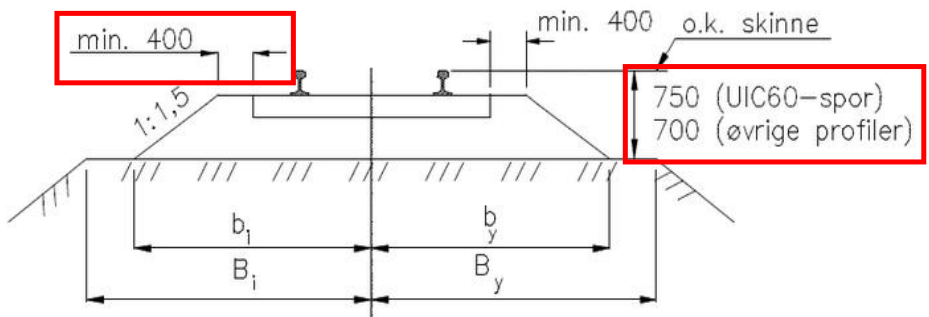
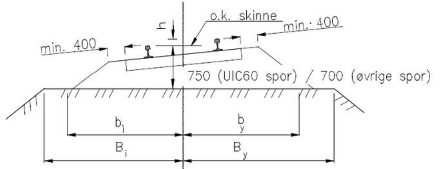
The ballast shoulder profile becomes especially important in tight curves. Bane NOR calls for increased shoulder width below 500 m radius with timber sleepers and below 400 m with concrete sleepers (TRV:03458). The applicable profile drawing and sleeper-specific table must be used; the BNF60/BNF60+ column is not interchangeable with the general concrete-sleeper column. For design speeds above 200 km/h, TRV:03457 adds 50 mm to the specified ballast height. See the current ballast profiles and drawings [179].
Compare the uncanted section in Figure 11.10(a) with the canted section in 11.10(b). The change in track geometry affects the ballast cross-section; the drawings must be read with the stated dimension reference and current profile requirements.
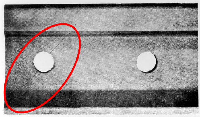
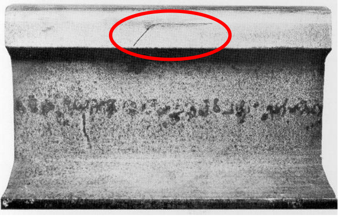
The bolt-hole crack in Figure 11.11(a) and head-region cracking in 11.11(b) illustrate different locations requiring rail-condition assessment. Welding rails into a continuous string does not remove defects already present in the material.
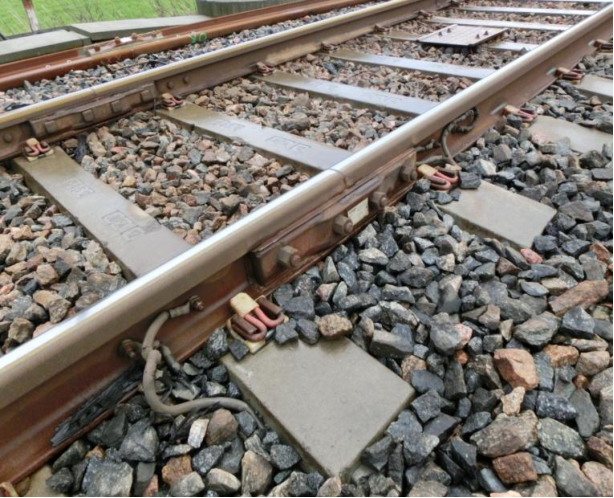
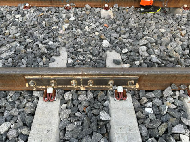
The lecture also names MT glued joints assembled in the track and six-hole Tenconi friction joints, alongside prefabricated glued type S joints and Exel friction joints. This identifies historical construction methods and the photographed examples. It is not the current approval list, which is stated above.
Figure 11.12(a) shows a glued type S joint, whereas 11.12(b) shows the historical Tenconi friction joint. Comparing their construction helps identify the joint in the field, but the historical example does not establish present approval for permanent use.
Use the side view in Figure 11.13(a) to locate the insulating end post, then the sections in 11.13(b) to follow the fastening and insulation through the assembly. The component table identifies parts that are difficult to distinguish in a field photograph.
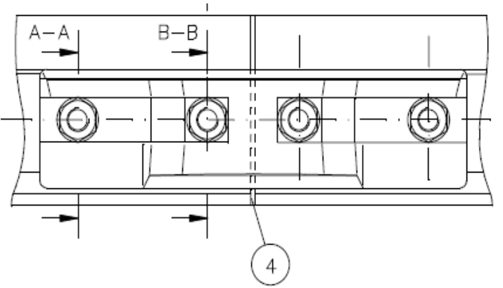
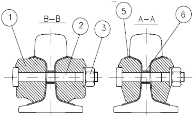
The reinforced type S drawing shows how the metallic load path is separated electrically by the end post, liners and bushes. The following quantities are transcribed from the lecture’s parts list for this drawing. In particular, its entry of one joint bar is preserved as a source-list value, not asserted to be the total number of bars in a complete two-sided joint. Selection, quantities and assembly for work must follow the approved product drawing.
| Position | Component | Quantity printed |
|---|---|---|
| 1 | Joint bar | 1 |
| 2 | Fishplate bolt | 4 |
| 3 | Nut | 4 |
| 4 | Nylon insulating end post, 6 mm | 1 |
| 5 | Dytron hard-woven insulating liner | 2 |
| 6 | Insulating bush | 4 |
11.3 Longitudinal Forces in CWR
In continuously welded rail, temperature change is converted into axial force because the rail cannot freely expand or contract. The following derivation establishes the basic force relation used throughout the chapter.
Temperature change is the main source of axial force in restrained rail. Lateral movement of curved track, turnouts, bridges and train acceleration or braking also change or redistribute the force. The following sections follow these mechanisms in the same order as the lecture.
11.3.1 Thermal Deformation and Force
Figure 11.14(a) allows free thermal expansion, while 11.14(b) allows elastic extension under tension. Neither sketch alone represents a fully restrained heated rail: restraint prevents the free length change and produces axial force instead.
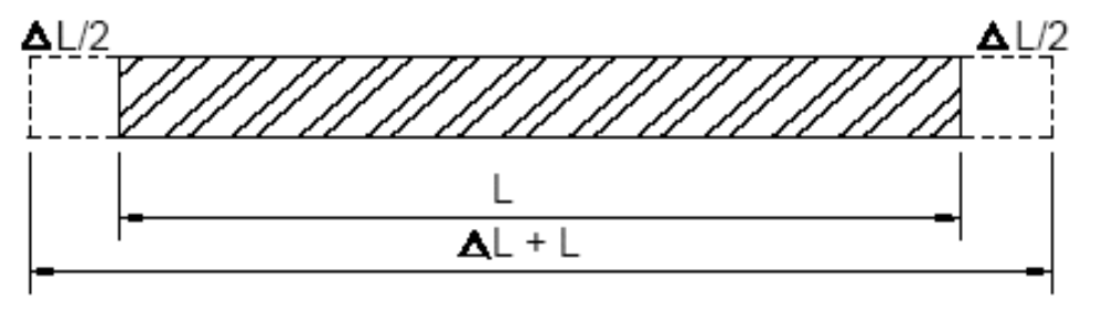
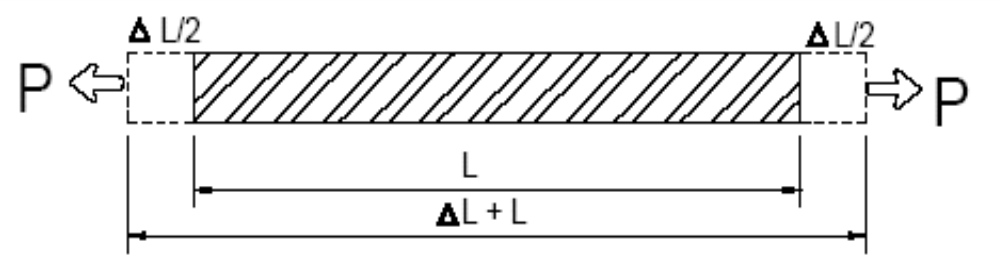
The two sketches describe different free-to-deform cases. A freely heated rail changes length by \(\Delta L=\alpha\Delta t L\). Under an applied tensile force \(P_t\), its elastic extension is \(\Delta L_\mathrm{el}=P_tL/(AE)\), equivalently \(\varepsilon_\mathrm{el}=\Delta L_\mathrm{el}/L=\sigma_t/E\) with tensile stress \(\sigma_t=P_t/A\). A restrained heated rail combines the thermal strain with an opposing elastic strain; its total extension is zero.
When a rail that is restrained from expanding is subject to a temperature increase \(\Delta t\), a compressive force builds up. When the temperature falls, tensile forces develop. The derivation combines Hooke's law with the thermal expansion equation. Consider a rail of cross-sectional area \(A\), elastic modulus \(E\), and linear thermal expansion coefficient \(\alpha\). For a fully restrained rail, expansion and contraction are prevented. Here \(\Delta t=T-T_{sf}\) is measured from the actual stress-free state; a negative value produces tension. The strain that would occur in a free rail is:
Full restraint means that the total longitudinal strain is zero. With extension-positive strains, \(\varepsilon_\mathrm{tot}=\varepsilon_\mathrm{el}+\varepsilon_\mathrm{free}=0\), so \(\varepsilon_\mathrm{el}=-\alpha\Delta t\). Hooke's law acts on this elastic strain. In Eqs. 11.2 and 11.3, stress \(\sigma\) and force \(P_\mathrm{rail}\) are defined as positive in compression. Thus:
Multiplying by the cross-sectional area gives the axial force in one rail:
Substituting the material properties of rail steel (\(\alpha = 1.15\times10^{-5}\,\mathrm{K}^{-1}\), \(E = 2.1\times10^5\,\mathrm{N\,mm^{-2}}\)):
The derived results are summarised above (Eqs. 11.2 and 11.3), where \(\alpha = 1.15 \times 10^{-5}\,\mathrm{K}^{-1}\) is the coefficient of thermal expansion of steel, \(E = 2.1 \times 10^5\,\mathrm{N\,mm^{-2}}\) is the elastic modulus, and \(A\) is the rail cross-sectional area in \(\mathrm{mm}^2\). In the practical form \(P_\mathrm{rail}\approx2.4\,\Delta t\,A\), use \(\Delta t\) in kelvin, \(A\) in \(\mathrm{mm}^2\), and the resulting \(P_\mathrm{rail}\) is in newtons.
The key insight is that the force in a restrained rail depends only on the temperature change and the cross-sectional area, not on the length of the rail. The total force in the two rails is \(P_\mathrm{tot}=2P_\mathrm{rail}\), so larger rail profiles develop larger restrained force for the same temperature change.
Worked example.
The legacy UIC60 example uses \(A = 7686\,\mathrm{mm}^2\). If the rail temperature is \(25\,^\circ\mathrm{C}\) above the stress-free temperature (\(\Delta t=25\,\mathrm{K}\)), the compressive force in one rail is
The total compressive force in both rails is therefore \(P_\mathrm{tot}=2P_\mathrm{rail}=922\,\mathrm{kN}\). If the temperature were \(25\,^\circ\mathrm{C}\) below the stress-free temperature, the magnitude would be the same but the force would be tensile.
| Profile | \(A\) [\(\mathrm{mm}^2\)] | \(P_\mathrm{tot}\) [\(\Delta t{=}1\,\mathrm{K}\)] | \(P_\mathrm{tot}\) [\(\Delta t{=}25\,\mathrm{K}\)] |
|---|---|---|---|
| S49 (49E1) | 6297 | 30.2 kN (3.0 tf) | 756 kN (76 tf) |
| S54 (54E3) | 6948 | 33.4 kN (3.3 tf) | 834 kN (83 tf) |
| UIC60 (60E1) | 7686 | 36.9 kN (3.7 tf) | 922 kN (92 tf) |
Approximate tonne-force equivalents use \(1\,\mathrm{tf}=9.80665\,\mathrm{kN}\approx10\,\mathrm{kN}\).
Rail-profile convention.
The cross-sectional areas in this chapter follow the legacy S49/S54/UIC54/UIC60 property set retained by the source calculations. Bane NOR maps these legacy names to 49E1, 54E3, 54E1, and 60E1, respectively [118]. Current EN 13674-1 manufacturer tables give slightly different nominal areas for some of these profiles [136]. The legacy values are retained so the worked examples and assignments use one internally consistent dataset. Project design must use the certified properties of the rail actually supplied.
11.3.2 Neutral and Stress-Free Temperatures
Neutral temperature is the reference state for assessing whether CWR is in compression or tension. Small changes in this reference can strongly affect buckling and fracture risk.
Definition
The neutral temperature \(T_n\) is the target stress-free rail temperature chosen in design and construction. At this temperature the rail is intended to be neither in compression nor tension. In service it is often useful to distinguish this target value from the actual stress-free temperature \(T_{sf}\), which can drift because of rail creep, lateral realignment, welding, or maintenance work.
where \(T_m=(T_\mathrm{max}+T_\mathrm{min})/2\) is the midpoint of the expected rail-temperature extremes. The lecture gives \(X=0\)–\(10\,\mathrm{K}\) as an illustrative upward shift to balance buckling and fracture risks. This relation explains the design choice; it does not replace an infrastructure manager’s prescribed target. These are stress-free-length principles; the rail must first be released from unintended restraint, and the applicable installation procedure must be followed. The target can be established by:
-
Laying the rail at the exact neutral temperature, or
-
Heating the rail to its neutral temperature before fastening, or
-
Mechanically stretching (tensioning) the rail to introduce the equivalent elongation before fastening
Bane NOR Requirements and Nordic Examples
Neutral-temperature rules are infrastructure-specific. Bane NOR specifies a target of \(+21\,^\circ\mathrm{C}\) (TRV:05305), with a \(\pm3\,^\circ\mathrm{C}\) tolerance for practical welding work (TRV:05308); local deviations require an approved exemption (TRV:05306). Table 11.4 distinguishes national rules and their fields of application. Welding temperature, stress-free target and allowable maintenance temperature must not be treated as interchangeable.
| Administration | Neutral temperature [\(^\circ\)C] | Tolerance [\(^\circ\)C] |
|---|---|---|
| Trafikverket | Geographically specified target | \(-3/+7\) around the target (2024 report) |
| Väylä, 2024 example for curves \(R<1000\) m | \(+17\) to \(+22\) (RATO 11, 15/2024, §11.1.1.1) | This bounded case is not a universal national target |
| Banedanmark | \(+22\) | \(\pm 7\) for \(V \leq 200\) km/h; \(\pm 3\) for \(200 < V \leq 250\) km/h |
| Bane NOR | \(+21\) | \(\pm 3\) |
Sources: Bane NOR construction rules [11], Trafikverket’s explanation of regional neutral temperatures [180] and 2024 buckling report, p. 17 [181], and Banedanmark BN1-66-3 (6 December 2023), §5.13 [182]. The Finnish value is the expressly bounded curve case in Väylä RATO 11, 15/2024, p. 5 [183]. This is a dated example from the original 15/2024 edition, replaced by 15/2024 v2 on 1 December 2024. Current work requires the applicable RATO edition and provisions.
Seasonal temperature example.
The lecture illustrates a rail-temperature range from \(-30\,^\circ\mathrm{C}\) to \(+55\,^\circ\mathrm{C}\). With \(T_{sf}=+21\,^\circ\mathrm{C}\), the rail is \(34\,\mathrm{K}\) above its stress-free state in the hot case and \(51\,\mathrm{K}\) below it in the cold case. Using the chapter’s legacy 49E1 area of \(6297\,\mathrm{mm}^2\) and the rounded coefficient \(2.4\,\mathrm{N/(mm^2\,K)}\) gives approximately 514 kN compression per rail and 771 kN tension per rail, respectively.
The preceding lecture slide uses \(-40\) to \(+55\,^\circ\mathrm{C}\), whereas this worked illustration uses \(-30\) to \(+55\,^\circ\mathrm{C}\). They are different example envelopes and must not be combined. With the adopted 49E1 area, the force change in one restrained rail is \(2.4\times6297=15\,112.8\,\mathrm{N/K}\), or about \(15.11\,\mathrm{kN/K}\). The diagram’s approximately \(1.5\,\mathrm{tf/K}\), 76 tf and 51 tf are coarse teaching estimates, rather than exact unit conversions of the kN results above.
The target therefore does not make the largest tensile and compressive forces equal. It balances two different failure risks: lateral buckling under compression and rail fracture under tension. These are rail temperatures, not an air-temperature forecast, and the example range is not a temperature envelope for every railway.
Read Figure 11.15 relative to its stress-free temperature: heating and cooling lie on opposite sides of the reference and produce opposite force signs in restrained rail. Use the adjacent kN calculation rather than the source's approximate tonnes-force labels.

Consequences of a Changed Stress-Free Temperature
If the actual stress-free temperature \(T_{sf}\) deviates from the designed \(T_n\):
-
\(T_{sf} > T_n\): increased tensile forces in winter \(\Rightarrow\) risk of rail fracture
-
\(T_{sf} < T_n\): increased compressive forces in summer \(\Rightarrow\) risk of track buckling / sun kink
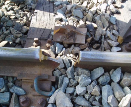
The separation in Figure 11.16 illustrates what a fractured rail can look like when the ends move apart. Cooling increases tensile demand in restrained rail, but a gap photograph alone does not establish what initiated the fracture.
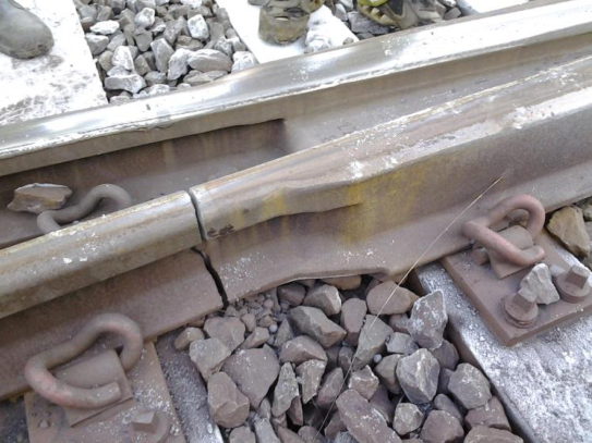
Figure 11.17(a) shows separated rail material at a gap; 11.17(b) locates cracking at a weld region. These views guide inspection of the fracture location, while the initiating mechanism requires material, temperature and service-history evidence.
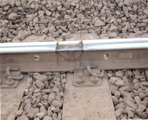
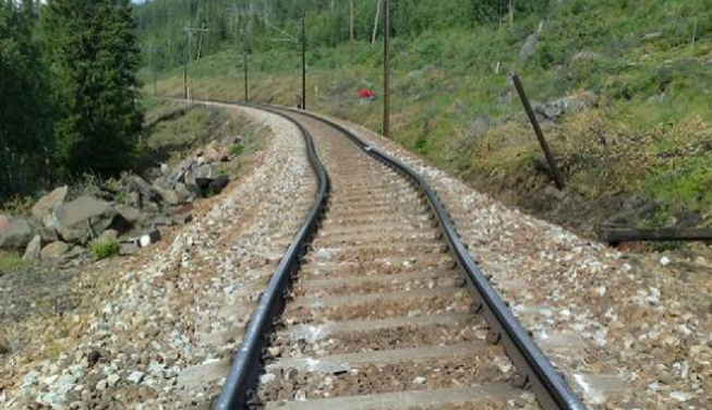
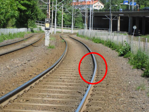
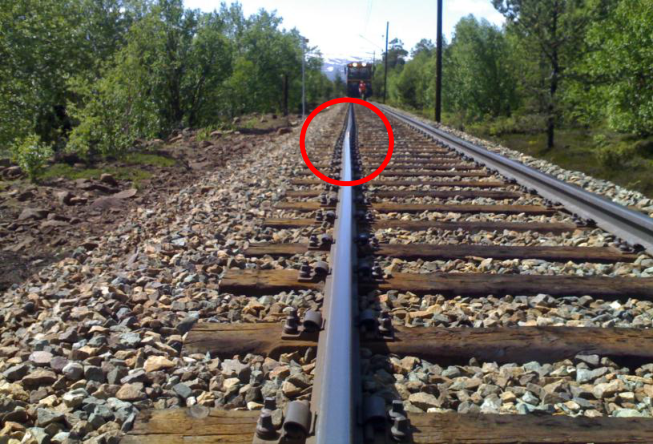
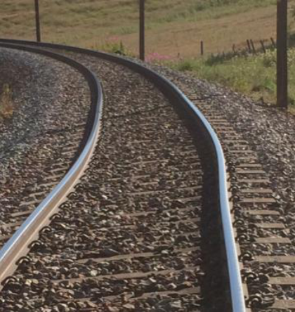
The canted-curve displacement in Figure 11.18(a), marked defects near infrastructure in 11.18(b) and along the rail in 11.18(c), and local curve kink in 11.18(d) illustrate geometry to investigate. Their role is to show possible manifestations, not to measure the low stress-free temperature discussed here.
11.3.3 Expansion Zones and Force Transfer
Figure 11.19 distinguishes the moving end zones from the locked central region. Follow the gradient from the rail end towards the centre when relating breathing length to the distributed longitudinal resistance.
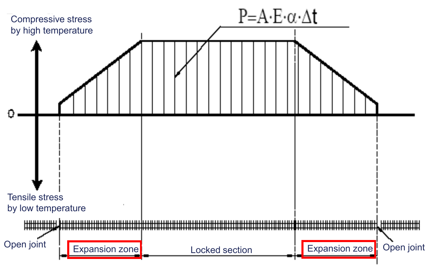
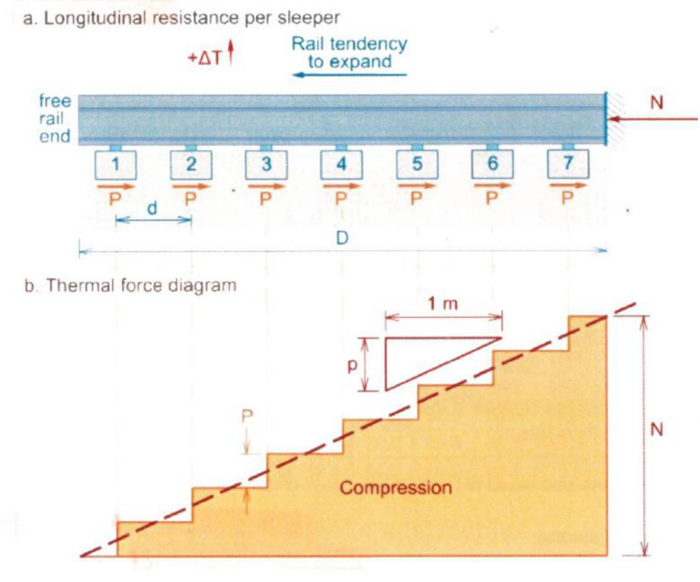
In a CWR track, expansion and contraction due to temperature changes occur only in the expansion zones at each end of the CWR section. In the central (locked) portion, large axial forces build up because longitudinal deformation is impossible. The equilibrium sketch in Figure 11.20 shows how longitudinal ballast resistance is mobilised over the breathing length at the rail end.
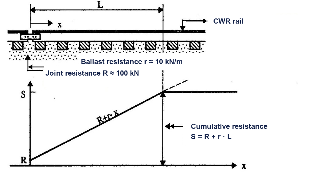
The steps in Figure 11.21 represent successive sleeper contributions to longitudinal restraint. The smooth gradient used in the calculation idealises these discrete transfers; it is not a separate physical load path.
The breathing length depends on temperature-force change and the available longitudinal restraint. Values of 50–100 m are useful illustrative magnitudes, not a universal minimum rail length. A central fully restrained zone exists in the simple model only if the section is longer than the sum of its two breathing zones. For two assumed 50 m zones, that means a length greater than 100 m; the Norwegian regulatory rule requiring rails longer than 50 m to be managed as CWR is a separate definition.
At a free rail end, the axial force is zero if end resistance is neglected. Moving towards the locked zone, longitudinal restraint transfers force into the rail. With constant resistance per metre, the axial force therefore increases linearly until it reaches the fully restrained thermal force. A larger temperature difference requires a longer breathing zone; stronger longitudinal restraint shortens it. The two ends behave in opposite directions: heating moves each free end outwards, while cooling draws it inwards. This explains why movement is concentrated near joints and other interruptions even though the central part of the rail hardly changes length.
The length of the expansion zone \(L\) is:
where \(P_\mathrm{rail}\) is the axial force in one rail to be transferred between the fixed CWR zone and the free end (kN), \(R_j\) is the residual resistance at the rail end or joint (kN), and \(r_\ell\) is the longitudinal track resistance per unit length for one rail (typically about 10 kN/m for well-compacted ballast). The mobilised resistance over the breathing zone is then \(r_\ell L\), so Eq. 11.5 is an equilibrium estimate, not a definition of the thermal force itself. Lengths of 80–100 m are possible examples, but must follow from the force and restraint in the actual case. This form uses force magnitudes for a fully mobilised transfer zone, with \(P_\mathrm{rail}>R_j\geq0\) and \(r_\ell>0\). It must not give a negative length on cooling or when joint resistance prevents movement; unloading and reversal require a separate account of the force history.
Worked example.
If one rail must transfer \(P_\mathrm{rail}=500\) kN into the locked zone and the longitudinal ballast resistance is \(r_\ell=10\) kN/m per rail, the breathing length is
neglecting residual joint resistance. This is a per-rail calculation, so the per-rail resistance must be used.
Compare the resistance curves in Figure 11.22 at the same temperature change. The selected longitudinal resistance changes the calculated breathing length, so the two horizontal example lengths cannot be read as general acceptance limits.
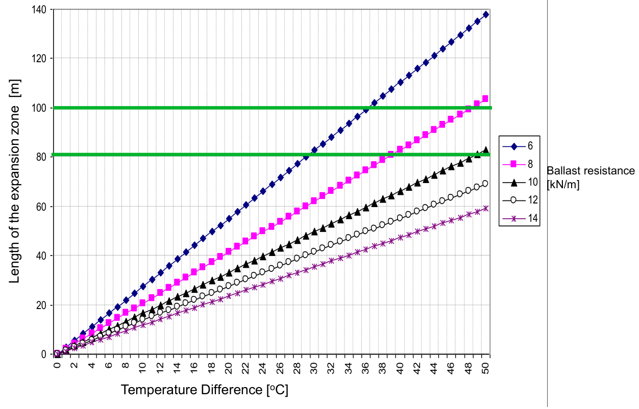
The parameter plot makes the restraint dependence explicit. At \(\Delta t=40\,\mathrm{K}\), the adopted 54E3 area gives \(P_\mathrm{rail}=2.4\times40\times6948=667\,008\,\mathrm{N}\). With no joint resistance, \(r_\ell=6\) and \(14\,\mathrm{kN/m}\) give breathing lengths of about 111 m and 48 m, respectively. Thus the lecture’s highlighted 80–100 m band cannot be assigned to every well-consolidated track without specifying the temperature change and longitudinal resistance.
11.3.4 Lateral Shift and Alignment Control
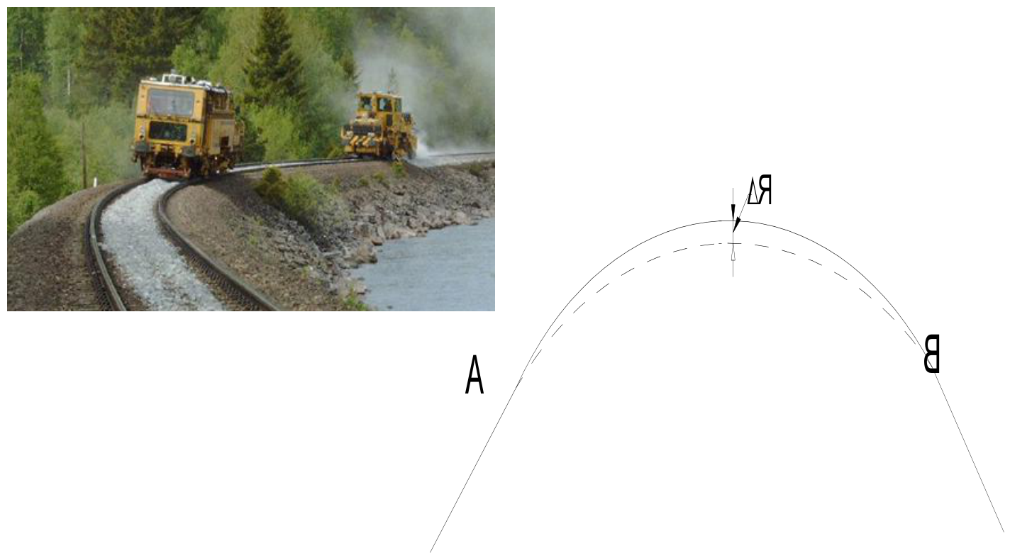
The lecture links low-temperature tamping and inward curve displacement to a loss of stress-free temperature. The tensile rail force can pull disturbed track inward during low-temperature work. Its preventive measures are to avoid unintended inward movement, maintain sufficient ballast support on the inside of the curve, verify the track position using permanent references, and neutralise when required. An enlarged inner shoulder must be designed under the applicable ballast provisions; it is not a substitute for correcting a displaced alignment. The actual temperature limits for tamping are given by the maintenance rules discussed in the section on track buckling.
Figure 11.23 connects curve tamping to the changed rail path between A and B. An alignment adjustment can change the length required by the curve even when no rail has been deliberately cut or stretched.
When the track in a curve is shifted laterally (e.g., by tamping for geometry correction), the stress-free temperature changes because the rail arc length changes:
where \(\Delta R\) is the inward radial shift of the track centreline and \(\alpha\) is the coefficient of thermal expansion of rail steel. The expression follows from equating the curvature-induced rail-length change to an equivalent free thermal strain.
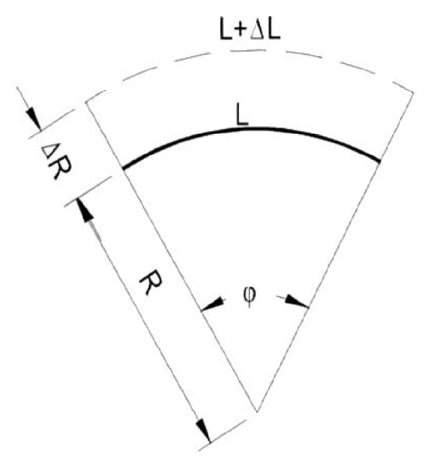
For the geometry in Figure 11.24, the angle \(\varphi\) is unchanged. With \(\varphi\) in degrees and the diagram's positive outward radius change,
Here the same continuous rail is moved onto a changed path, without cutting or adding rail. An outward shift raises the stress-free temperature. Equation 11.6 instead defines the radial shift as positive inwards, which reverses the sign.
Figure 11.25 quantifies the effect of lateral shift by relating side movement, curve radius, and equivalent stress-free-temperature change. A shift inwards (towards the centre of curvature) reduces the arc length, which is equivalent to reducing \(T_{sf}\), thereby increasing compressive forces. A 10 cm inward lateral shift in a curve with \(R = 300\) m reduces the stress-free temperature by \(29\,^\circ\mathrm{C}\), a very significant effect. An outward shift has the opposite sign: it raises the stress-free temperature and therefore increases the risk of winter tensile fracture. The sign convention is important: ordinary geometry correction can unintentionally change the stress state even when no rail is cut. The value follows from \(0.10/(1.15\times10^{-5}\times300)=28.99\) K; the original figure is an approximate illustration.
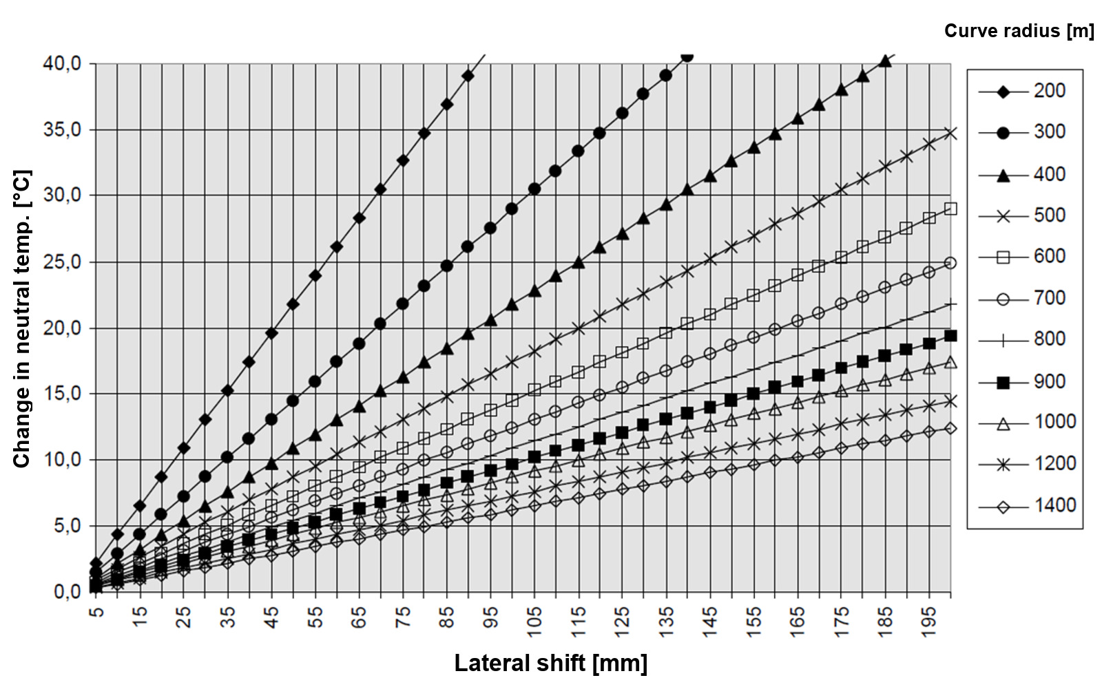
The before-and-after comparison in Figure 11.26 links inward displacement to a changed stress-free condition. Keep the original approximate force labels separate from the recalculated values using this chapter's stated coefficient.
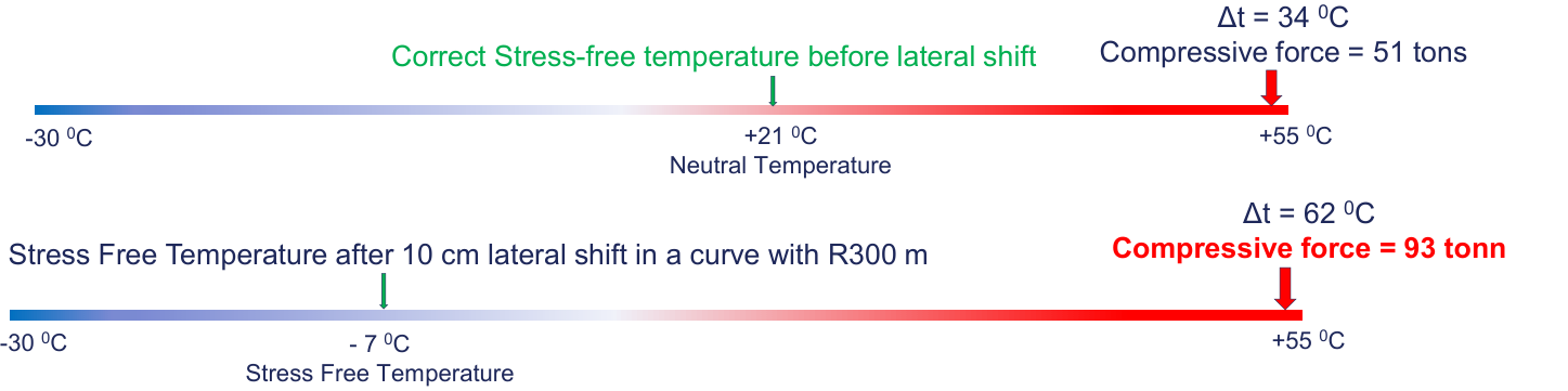
For the same 49E1 example, an initial \(T_{sf}=21\,^\circ\mathrm{C}\) becomes approximately \(21-28.9855=-7.99\,^\circ\mathrm{C}\) after a 0.10 m inward shift at \(R=300\,\mathrm{m}\). At a rail temperature of \(55\,^\circ\mathrm{C}\), the compressive temperature difference becomes \(62.99\,\mathrm{K}\). Keeping the chapter’s rounded force coefficient, the force is \(P_\mathrm{rail}\approx2.4\times6297\times62.9855=951\,887\,\mathrm{N}\), or about 952 kN per rail, compared with 514 kN before the shift. The original diagram uses the coarser 28 K and 1.5 tf/K approximations, which produce its labels of \(-7\,^\circ\mathrm{C}\), 62 K and 93 tf. Neither calculation proves that buckling will occur; it shows the additional compression that the track must resist.
Table 11.5 gives the horizontal-position tolerances in TRV:05056. These are deviations from the designed track position, rather than local alignment defects measured on a short chord.
| Quality class and speed | Curve radius | Newly adjusted, ±mm | Maintenance limit, ±mm |
|---|---|---|---|
| Q0–Q1, \(160<V\leq300\) km/h | All | 20 | 30 |
| Q2–Q5, \(V\leq160\) km/h | \(R>1000\) m | 40 | 60 |
| Q2–Q5, \(V\leq160\) km/h | \(750<R\leq1000\) m | 40 | 40 |
| Q2–Q5, \(V\leq160\) km/h | \(500<R\leq750\) m | 30 | 30 |
| Q2–Q5, \(V\leq160\) km/h | \(350<R\leq500\) m | 20 | 20 |
| Q2–Q5, \(V\leq160\) km/h | \(R\leq350\) m | 15 | 15 |
Source: Bane NOR, horizontal track position, TRV:05056–05060 [50]. Exceeding a maintenance limit requires correction at the first opportunity; inward displacement discovered in spring has high priority. Neutralisation is not a general permission to leave an out-of-tolerance alignment unchanged. Clearance requirements also govern if the designed position would cause a conflict (TRV:05060).
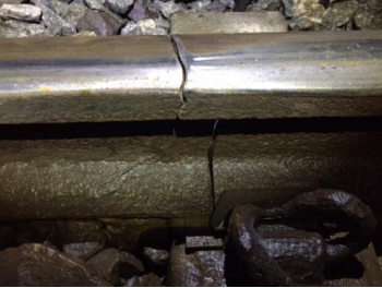
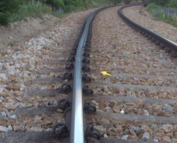
Figure 11.27(a) illustrates fracture, the risk associated here with an outward shift and increased stress-free temperature; 11.27(b) illustrates buckling, associated here with an inward shift and reduced stress-free temperature. The photographs do not prove that either shift actually preceded the photographed event.
11.3.5 Track Neutralisation
Track neutralization establishes the intended stress-free rail length at installation and restores it during service when necessary. The reference is the designed neutral temperature \(T_n\). It is required when:
-
The actual stress-free temperature is outside the permitted neutral-temperature range, rather than merely different from its target value
-
The applicable construction or maintenance procedure requires neutralisation. TRV:05022 requires it after specified major interventions in track without permanent position references. TRV:05024 and TRV:05025 provide conditional exceptions for limited work or correctly neutralised, referenced track whose position can be verified
The following is the mechanical principle, not a complete work instruction:
- Establish the rail temperature, target neutral temperature, treatment length and reference marks under the approved procedure.
- Release the rail from the restraint that would prevent stress redistribution, including the specified fastening release and rail cut. Rollers lift the rail clear of its seats, and the prescribed vibration or knocking overcomes residual friction. The rail must be able to reach a known, released condition before the required extension is applied.
- Within the permitted neutral-temperature band, release the stress and refasten as specified. Below that band, use controlled heating or mechanical tensioning to give the released length the extension corresponding to \(T_n\), with the required allowance for closure welding. A rail that is too hot cannot be corrected simply by pulling it further.
- Verify the extension along the treatment length, fasten the rail in the specified sequence, make the closure weld and record the completed neutralisation.
Simply cutting and rewelding a short gap does not demonstrate that the whole intended length has been neutralised. Residual restraint, uneven extension and movement during the work can leave a non-uniform stress state. The detailed Bane NOR neutralisation procedure [184], required by TRV:05359, governs the operation. It distinguishes stress release within the neutral-temperature band from controlled extension below it and specifies equipment, anchorage, measurement and welding conditions. Hydraulic tensioning is recommended; a heating trolley must not be used below +10 °C rail temperature. Closure welding above the neutral-temperature band is prohibited (TRV:05376), and the work must be led by personnel qualified under TRV:05360.
Worked example.
For a released, stress-free rail length of 100 m at \(14\,^\circ\mathrm{C}\) and a target neutral temperature of \(21\,^\circ\mathrm{C}\), the required equivalent extension before fastening is
The same extension may be introduced by heating the rail or by mechanical tensioning before fastening.
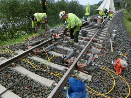
The closure weld completes the operation. The aluminothermic welding sequence is illustrated in Figure 11.4.
The target and tolerance for neutralisation come from Bane NOR construction rules, TRV:05305–05308 [11]. Work temperatures and post-work restrictions come from the maintenance rules [6]. EN 14587-2 concerns mobile flash-butt rail welding, and EN 14730-2 concerns qualification of aluminothermic welders, approval of contractors and acceptance of welds; neither supplies the Norwegian neutral-temperature target or tamping-temperature limits.
The tensioning equipment in Figure 11.28 applies controlled rail extension during neutralisation. Its role is to establish the intended stress-free condition before closure, rather than merely to pull a visible gap shut.
11.3.6 Turnouts and Adjoining Track
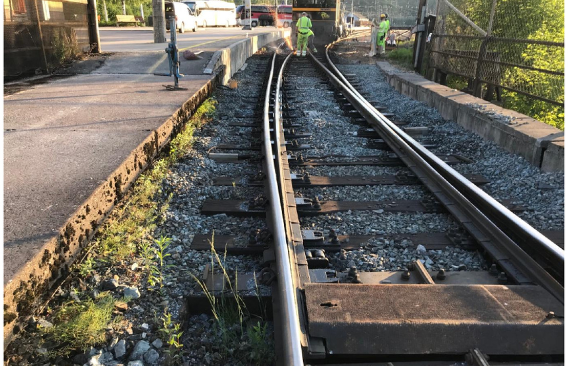
Turnouts create additional longitudinal forces because they act as semi-fixed points in the rail. The axial forces in stock rails are locally increased in the switch part. Technical regulations therefore require special attention to welding sequence, neutralisation, and the longitudinal position between switch rail and stock rail when a turnout is welded into CWR [10, 12].
The stock rails, switch rails, common sleepers and adjoining track do not move independently. Longitudinal load can be transferred through the turnout structure, producing local rail-force peaks and sleeper bending. Keeping the breathing zones outside the turnout reduces one source of relative movement. This is also why the welding and neutralisation sequence must consider the adjoining track, not only the turnout itself.
The turnout example also shows why prevention is a system problem. Depending on the approved design, measures may include longitudinal rail anchors, heavier or specially shaped sleepers, and clean, well-confined ballast. The adjoining tracks must be considered in the neutralisation plan so that their movement does not concentrate in the turnout.
For a turnout in a CWR main track, Bane NOR requires the adjoining track to remain continuously welded for at least 60 m from the turnout (TRV:05438). In timber-sleeper track, TRV:05439 specifies 100–200 rail anchors over at least 60 m, alternating between restraint against compressive and tensile forces. These are longitudinal rail anchors, distinct from the transverse sleeper anchors discussed in Section 11.4. See the turnout construction requirements [185]. This 60 m adjoining-CWR requirement is distinct from the neutralisation scope: TRV:05445 requires neutralisation at least 60 m from the six end joints for turnout base radius below 1200 m; TRV:05446 additionally includes the turnout’s continuous rail strings at base radius 1200 m or greater.
Figure 11.30 shows a field example of track buckling at Hønefoss, where the lateral track displacement is visible through the turnout area.
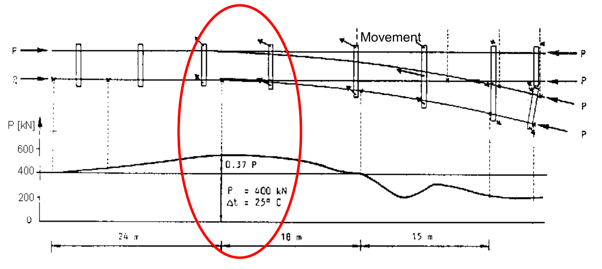
Figure 11.29 shows that the measured force varies through the illustrated turnout rather than remaining uniform. Treat the local stock-rail increase as a case-specific interaction with turnout geometry and restraint, not a universal multiplier.
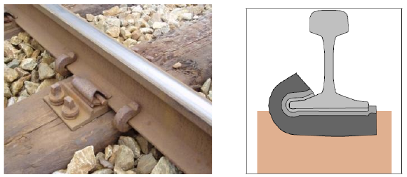
The anchor and section in Figure 11.31 show how rail movement is resisted through contact with the sleeper. This is a longitudinal restraint detail, distinct from the transverse sleeper anchors introduced later.
11.3.7 Bridges and Rail Expansion Devices
Rail and bridge movements interact because the deck and rails have different thermal and longitudinal restraint conditions. Bane NOR uses the bridge’s expansion length, not simply its overall length, for the following selected requirements. Expansion length is the sum of bridge lengths whose movement is released through movable bearings at the same location:
- Steel bridge without continuous ballast: expansion length \(D>100\) m requires a rail expansion device at the movable bearing (TRV:03495).
- Steel bridge with continuous ballast: expansion length over 90 m requires rail expansion devices (TRV:03485).
- Concrete or composite bridge with continuous ballast: expansion length over 120 m requires rail expansion devices (TRV:03484).
For steel bridges without continuous ballast with \(10<D\leq100\) m, TRV:03498–03500 instead specify no rail expansion device, sliding fastenings and CWR extending at least 150 m beyond each abutment. TRV:03521 specifies Pandrol Railfree sliding fastenings. These clauses do not remove the need for the applicable track–bridge interaction analysis. Figures 11.34 and 11.38 show the expansion device and sliding fastening separately. See Bane NOR, Track on bridges [186]. For the separate case \(D\leq10\) m, TRV:03501–03503 require the approach-track fastening, no rail joint on the bridge, and any transition from CWR to jointed track at least 150 m from the bridge; the fastening conditions in TRV:03519 also apply. For \(D>100\) m, normal resilient fastenings are required (TRV:03496), with additional rail anchors on the specified timber-sleeper approaches without resilient baseplates (TRV:03389).
How the bridge changes the rail force
Without a rail expansion device, movement of the bridge deck is transferred through the rail supports and adds local force to the temperature-induced force already present in the CWR. The additional force varies along the bridge and its approaches, so the ordinary locked-zone force does not describe every cross-section. A movable bridge bearing allows the deck to move; it does not by itself release the longitudinal rail force.
In Figure 11.32, follow the local changes in rail force and displacement where bridge movement interacts with the continuous rails. The sketch describes the interaction qualitatively; a bridge calculation still requires its actual restraint and movement conditions.
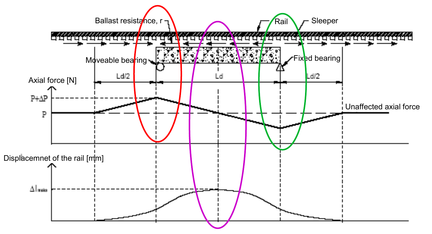
Figure 11.33 adds an expansion device to the bridge interaction. Movement accommodated at the device includes the bridge contribution and adjacent rail breathing, so device travel cannot be determined from bridge expansion alone.
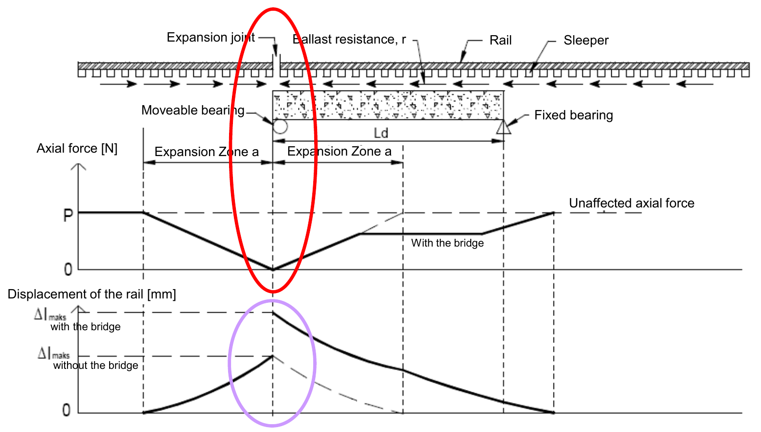
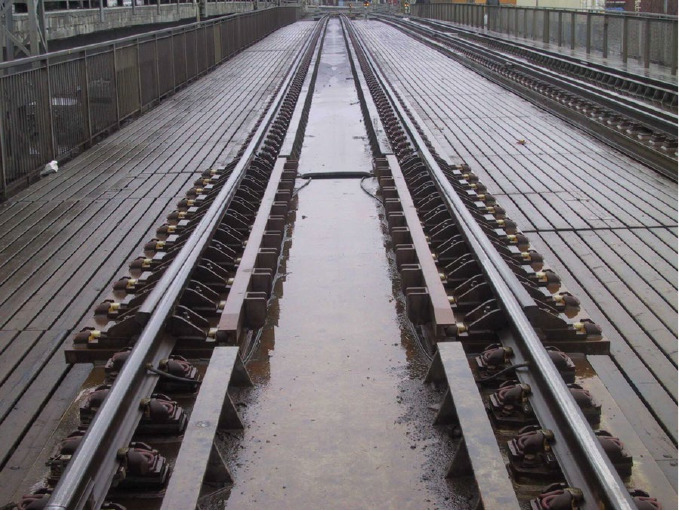
Figure 11.35 places the expansion device at a ballasted bridge approach during construction. The field setting helps connect the movement detail to its surrounding track support and bridge interface.
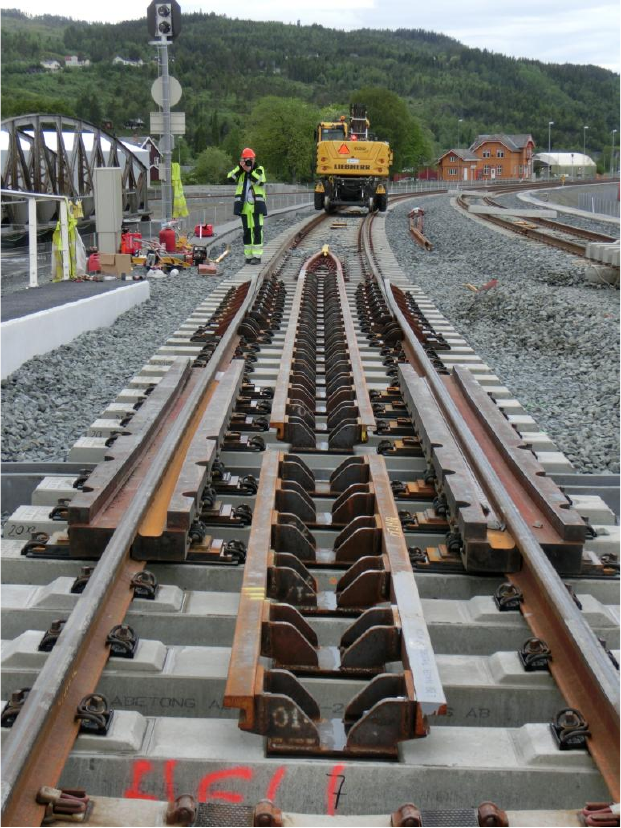
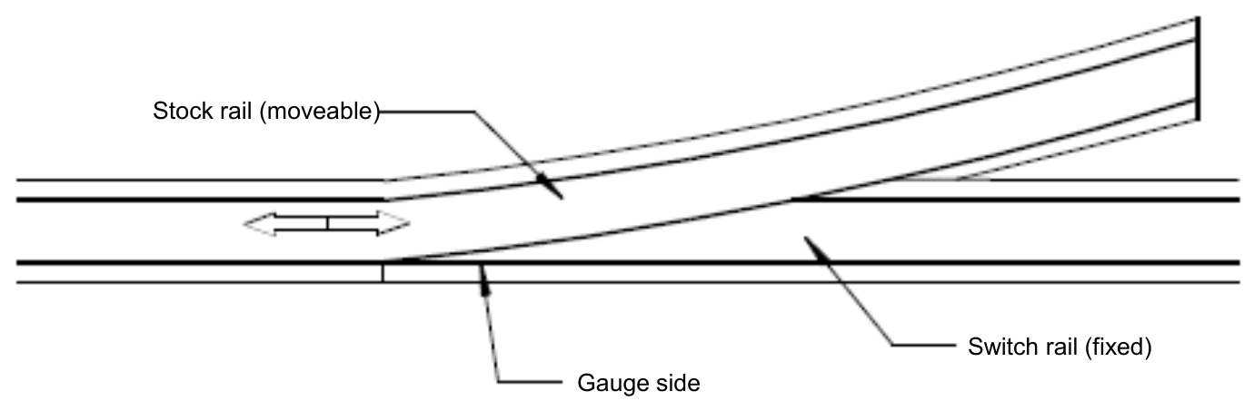
Identify the movable stock rail and fixed switch rail in Figure 11.36. Their overlapping geometry accommodates longitudinal displacement while maintaining the gauge-side running edge, unlike an ordinary open rail-end gap.
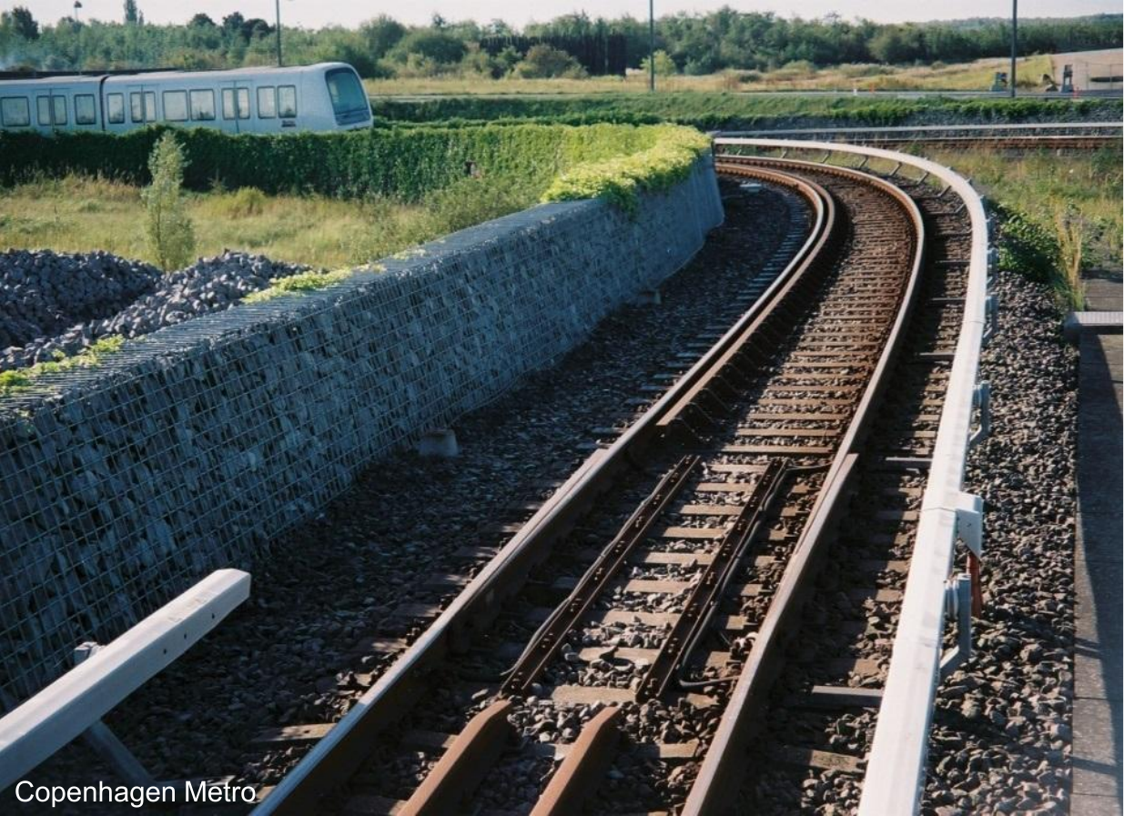
The curved installation in Figure 11.37 demonstrates one system-specific solution. Its value is to show that geometry and movement accommodation must be designed together, not to establish that every expansion device is suitable for a curve.
The section in Figure 11.38(a) identifies the sliding fastening's spring and shims; 11.38(b) shows those details in the installed e2071 assembly. The rail is supported and guided while longitudinal sliding is intentionally accommodated.
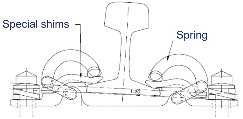
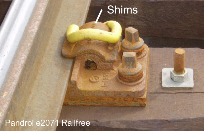
Figure 11.39 shows a bridge track without the conventional ballast bed. The support and fastening interfaces therefore need to be identified directly when assessing how bridge movement and rail forces are transmitted.
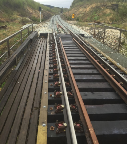
A rail expansion device accommodates relative rail movement at a selected location. Its required movement allowance depends on bridge movement and on the breathing of the adjoining rail lengths. It should therefore not be sized from free bridge expansion alone. Sliding fastenings serve a different purpose: they reduce the longitudinal force transferred between the deck and the rail while retaining the specified rail support and guidance.
In the illustrated expansion-device geometry, one rail can move longitudinally while the overlapping stock-rail and switch-rail arrangement maintains the gauge-side running edge. The Copenhagen Metro photograph shows a curve application. For Bane NOR, that example does not override TRV:07817, which recommends a straight alignment, or the prohibitions for horizontal radius below 250 m and vertical radius below 10,000 m in TRV:08230–08231. The Railfree detail illustrates a different mechanism: special shims and spring geometry permit longitudinal rail movement at the support while retaining lateral guidance. The photograph identifies the illustrated component as Pandrol e2071.
11.3.8 Rail Creep and Longitudinal Restraint
Bane NOR cites US heavy-freight tests in which braking or acceleration transferred longitudinal forces of up to 260 kN to the rails [16]. Repeated movement can produce rail creep, a gradual net displacement relative to the sleepers, and alter the stress-free state. The same teaching source gives a model example of braking on a 15‰ downgrade in which the additional force in UIC60 rail corresponds to about a 10 °C reduction in stress-free temperature. Neither value is a universal maximum. Suitable fastenings, longitudinal ballast restraint and, where used, rail anchors resist creep.
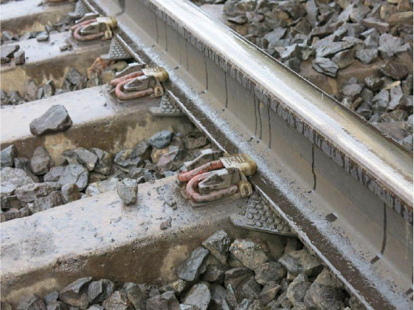
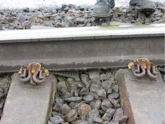
Field indications include skewed sleepers, clips displaced from their normal position and rail pads that have moved under the rail foot. These observations indicate that restraint or movement needs investigation; they do not directly measure the stress-free temperature. Inspection should consider the rail, fastening and ballast interfaces together, especially near braking locations, gradients, turnouts and changes in track construction.
Creep prevention therefore includes maintaining the specified clips, insulators and pads, checking their seating and clamping action, and restoring the designed longitudinal restraint. A different fastening with greater clamping capacity is an engineering design choice requiring system compatibility; tightening or replacing components ad hoc is not a substitute for the approved assembly.
The load path through the fastening, rail pad and sleeper–ballast interface is shown in Figure 11.3. The weakest interface can limit the restraint available to resist creep.
The skewed sleepers in Figure 11.40 are a field clue to relative longitudinal movement. Confirm that interpretation using reference measurements and the fastening and support condition rather than assigning a rail force from the photograph.
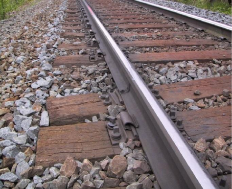
The displaced pads in Figure 11.41(a) and rotated clips in 11.41(b) identify rail-seat details to inspect for relative movement and loss of proper engagement. They do not quantify creep distance or stress-free temperature.
11.4 Lateral Track Resistance
Lateral track resistance is the main stabilising force against sideways movement of CWR. It depends on the combined contribution of rails, fastenings, sleepers, ballast profile, and ballast consolidation.
Figure 11.42 introduces the stability question: the track frame must retain alignment under the applied actions. Its exaggerated geometry is illustrative, so use the following mechanical diagrams rather than this image for analysing deformation.
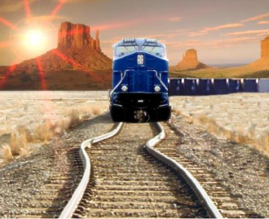
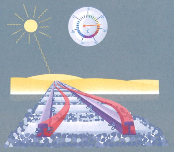
Figure 11.43 links heating, compressive force and possible lateral deformation conceptually. Heating alone does not specify the buckling threshold; restraint, imperfections and resistance must also enter the stability assessment.
11.4.1 Resistance Mechanisms
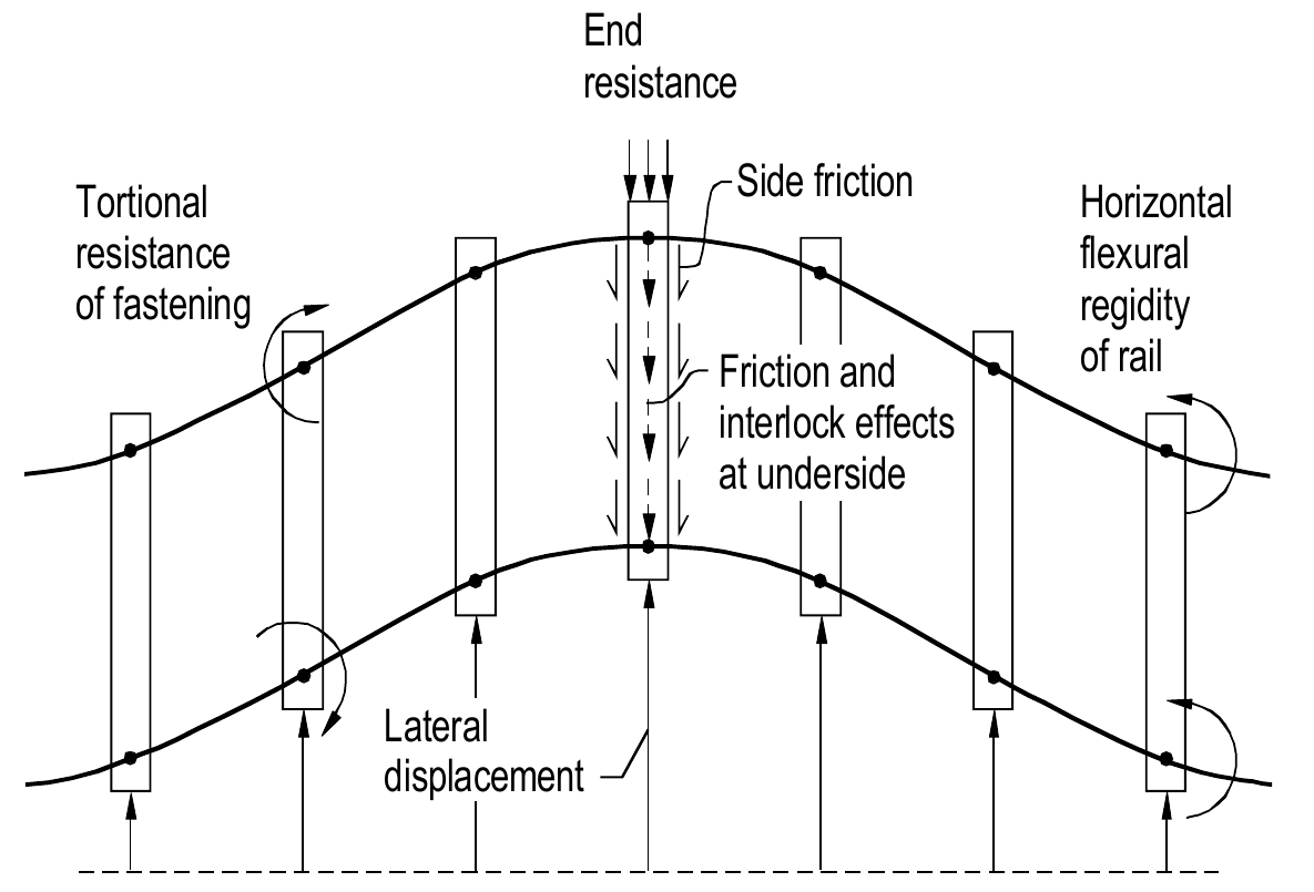
The Lateral Track Resistance (LTR) is the resistance of the track panel and ballast against cumulative lateral displacement. It is the key parameter governing the safety of CWR track against buckling, and its resistance comes from four main contributions:
-
Rail bending stiffness (horizontal/lateral second moment of area, not the vertical bending inertia used for rail-seat bending)
-
Fastening torsional resistance: depends on clamping force, rail-seat dimensions and pad friction; worn pads and insulators can reduce resistance
-
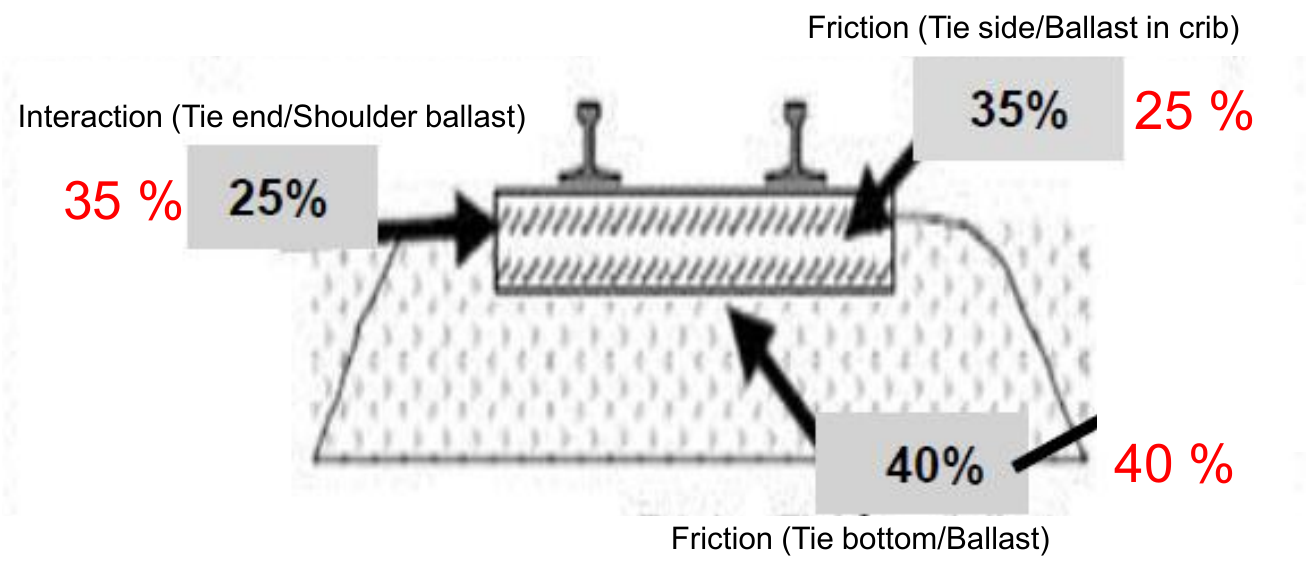
Sleeper–ballast lateral resistance: bottom friction (about 40%), sleeper-end interaction with the ballast shoulder (about 35%), and sleeper-side friction against ballast in the cribs (about 25%). These are illustrative contributions for a monoblock sleeper, not fixed design proportions
-
Ballast quality and profile: shoulder width, crib filling, ballast grain size, degree of consolidation
Track construction and maintenance condition must both be specified when comparing lateral resistance. The lecture uses an unconsolidated ballast state as a common comparison condition for different designs. This helps separate the design effect from the gain caused by traffic or mechanical consolidation, but does not make all unconsolidated tests equivalent: the ballast profile, applied vertical load, test length and displacement criterion must also match.
11.4.2 Rail and Fastening Rigidity
Track-panel rigidity. The rails resist lateral bending, while the fastenings resist rotation of the rail relative to the sleepers. Together they determine how the panel deforms between its ballast supports. Rail-foot width, lateral second moment of area, rail-seat contact area, pad properties and clamping force all matter. Worn pads or insulators can reduce the fastening contribution. A larger rail profile can improve lateral rigidity, but it also develops a larger thermal force for the same temperature change. Both effects belong in the assessment.
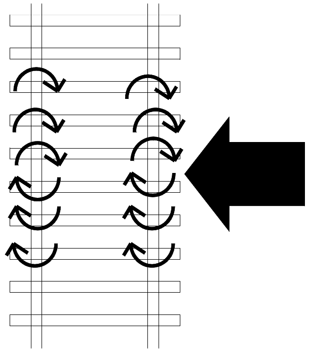
Figure 11.44 separates bending of the rails from rotation at the fastenings under lateral loading. Both contribute to the track panel response, which is why rail stiffness alone is not the stiffness of the complete frame.
Compare the steel distribution in the light section in Figure 11.45(a) with 60E1 in 11.45(b). The dimensions determine the relevant second moment of area; total mass alone cannot describe resistance to lateral bending.
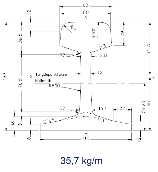
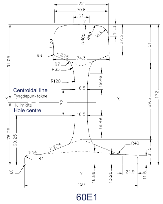
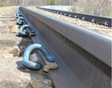
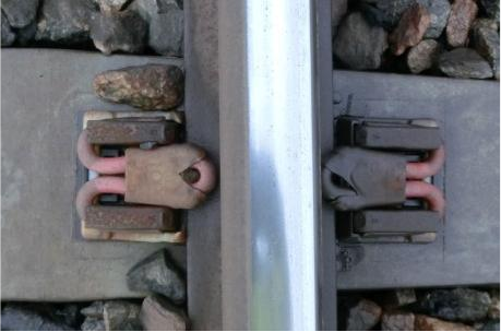
Figure 11.46(a) shows the resilient fastening and rail-seat contacts; 11.46(b) shows worn pads and insulators. Loss of proper contact can change rotational restraint, so the fastening must be assessed as an assembly rather than by clip presence alone.
The red contact lengths in Figure 11.47 show a geometric difference between fastening configurations. The comparison helps locate the rotational restraint, but contact length alone cannot establish the assembly's rotational stiffness.
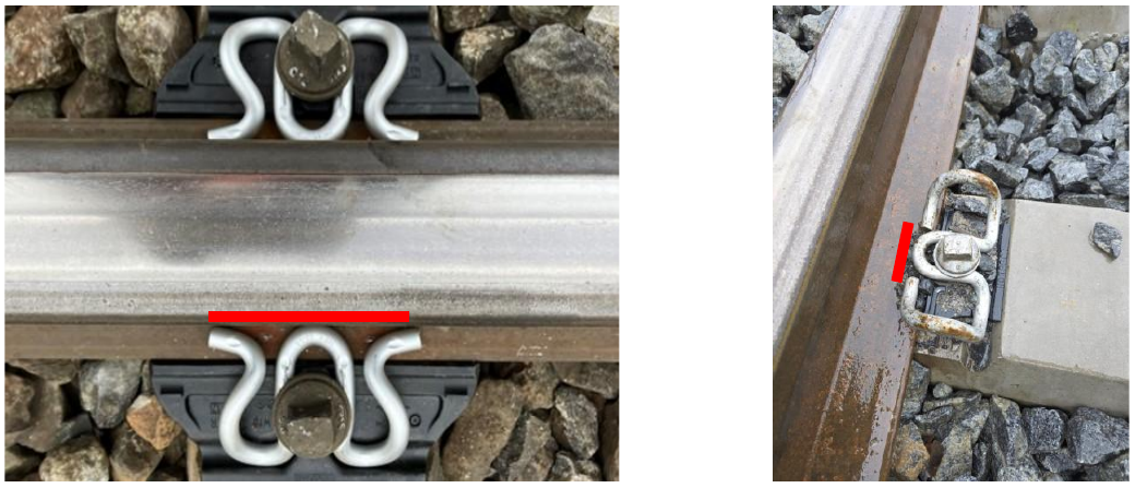
The rail foot, web and head all contribute to the cross-section’s bending properties. At each rail seat, rotation is resisted by clamping, pad friction and lateral support from the baseplate bracket or cast-in shoulder. The lecture lists rubber, polyurethane and cork as examples of pad materials whose friction and deformation behaviour differ. Contact area and wear condition matter as well. Its comparison of Vossloh M-clip and W30HH configurations illustrates this contact mechanism; it is not a product ranking or a declaration of Norwegian approval. The shorthand “rail bending stiffness + fastening torsional resistance” denotes interacting contributions to panel behaviour, not the direct numerical addition of quantities with different units.
11.4.3 Sleeper Type, Spacing and Anchors
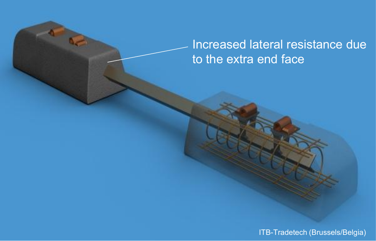
Sleeper shape and ballast engagement. Sleeper weight is only part of the explanation. Twin-block sleepers provide additional end faces against the ballast; Y-shaped steel sleepers and connected sleeper frames change the panel geometry and the way load is distributed. Their performance cannot be inferred from material alone. Closer sleeper spacing provides more restraint points per metre, but the gain also depends on the ballast between neighbouring sleepers.
Figure 11.48 compares sleeper types under the conditions of the historical tests. Use the spread to recognise sensitivity to support and sleeper geometry, not to assign a current design factor to every sleeper of a given material.
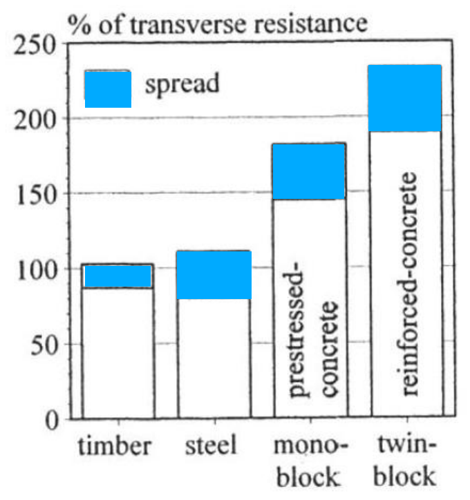
Figure 11.49 divides ballast restraint between the sleeper underside, sides and ends. The differing percentage sets demonstrate that the distribution is condition-dependent; they should not be added or transferred as universal constants.
The cutaway in Figure 11.50 makes the additional ballast-engaging faces of the twin-block sleeper visible. This connects sleeper geometry to the end-face contribution in the preceding resistance diagram.
The profiled sleeper in Figure 11.51(a), frame arrangement in 11.51(b) and scalloped example in 11.51(c) use different shapes to engage ballast or stiffen the frame. The detail in 11.51(d) explains the scalloped contact geometry. Their mechanisms must be distinguished before comparing performance.
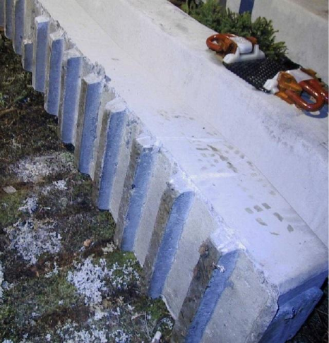
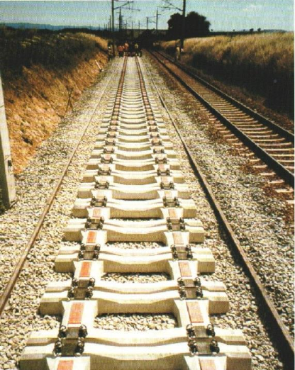
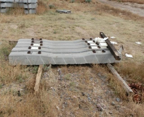
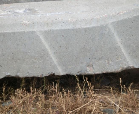
Figure 11.52 connects the profiled underside to a deeper shear zone in the ballast. The intended resistance comes from mobilising ballast friction and interlock, so an intact profile without suitable ballast contact is not sufficient.
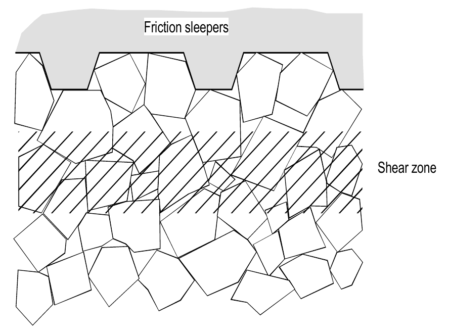
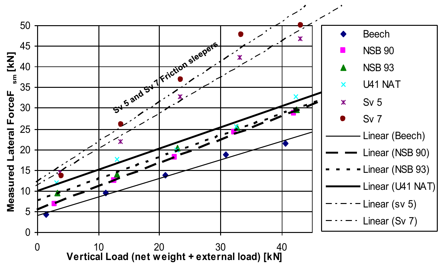
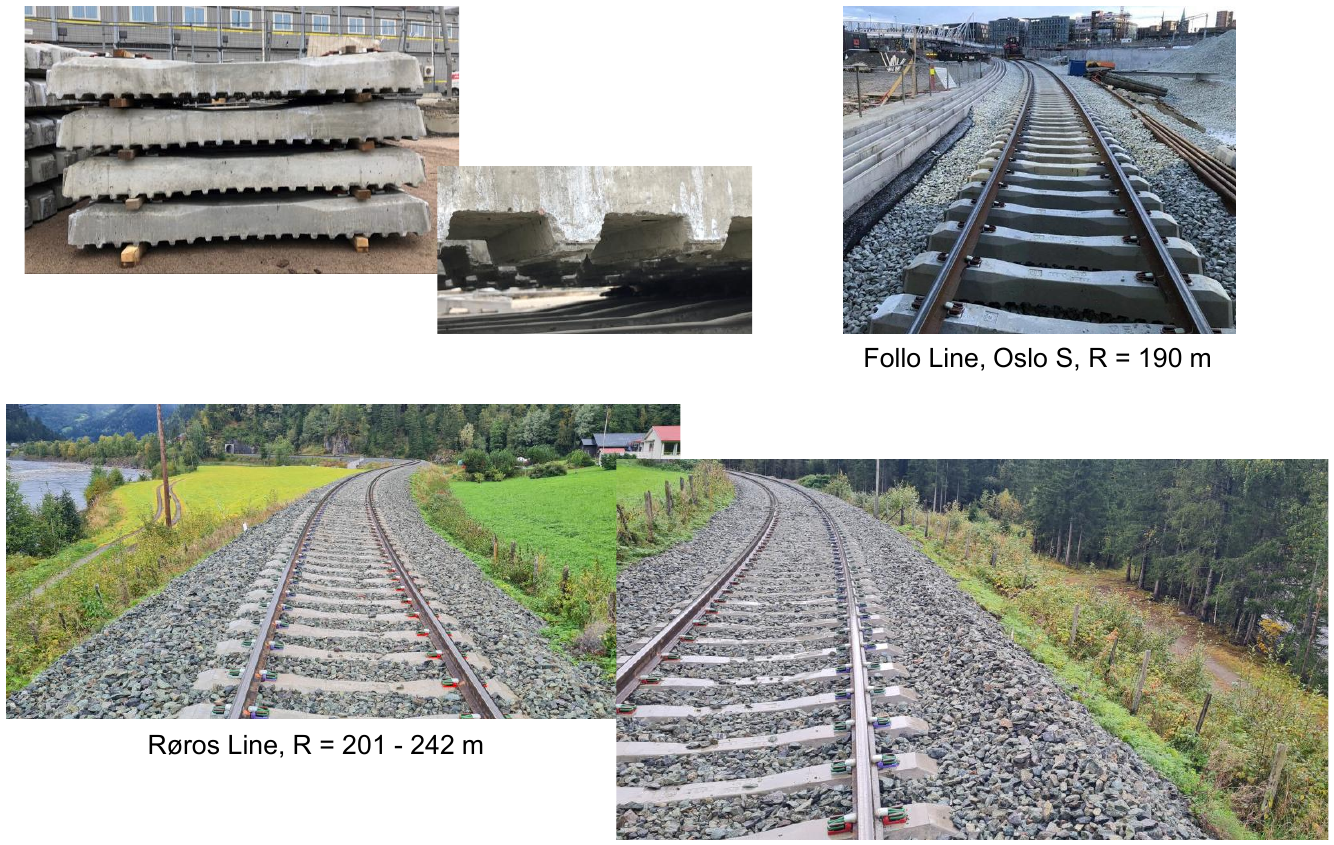
Figure 11.54 relates the stored sleeper's underside to the named field installations. The stated curve radii locate these examples; they are not a stand-alone rule for selecting a friction sleeper at another site.
The designs in Figure 11.55 alter sleeper mass, ballast engagement or frame connection in different ways. Use the catalogue to compare these mechanisms, while keeping product approval and quantitative resistance separate from the illustration.
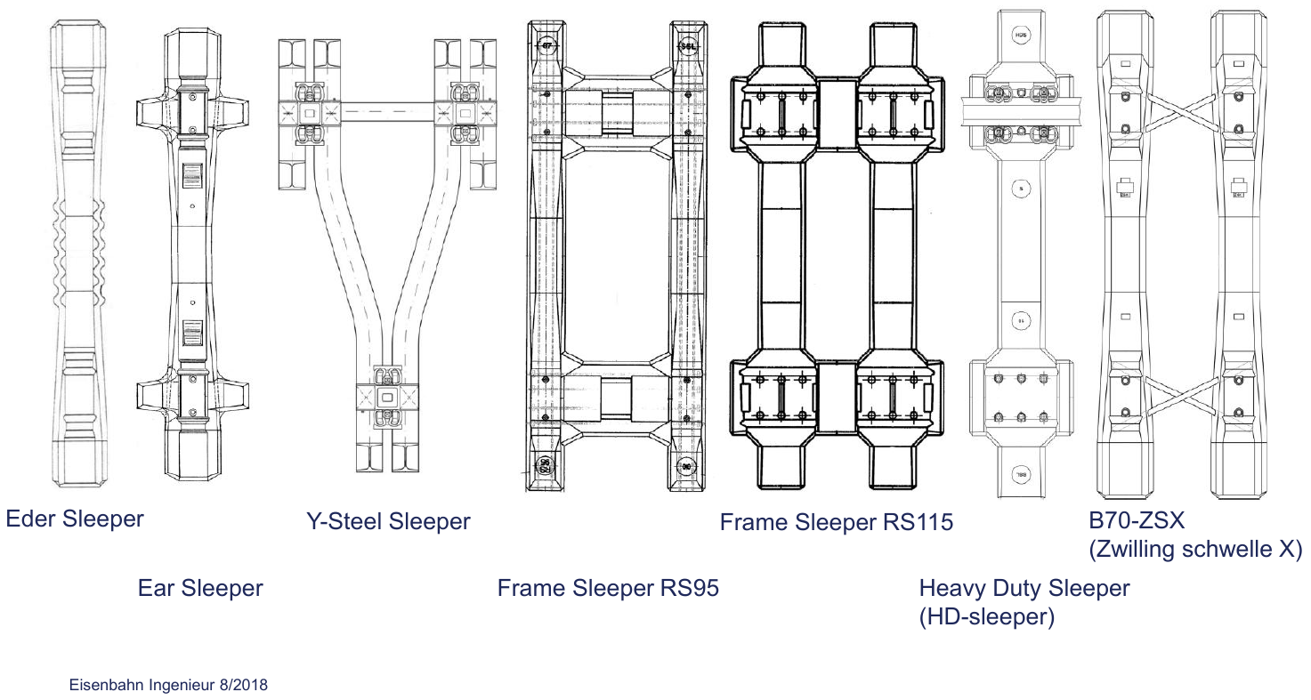
Figure 11.56 compares deformation of an ordinary sleeper panel with the cross-braced arrangement under a transverse force. The different shapes explain a stiffness mechanism, but no numerical stiffness ratio can be read from these schematic deflections.
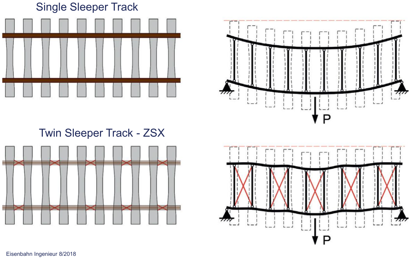
Figure 11.57(a) places pressed-steel sleepers in the construction setting, 11.57(b) shows their section and dimensions, and 11.57(c) shows the different Y-shaped arrangement. Shape and ballast engagement vary even within the category of steel sleepers.
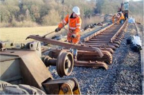
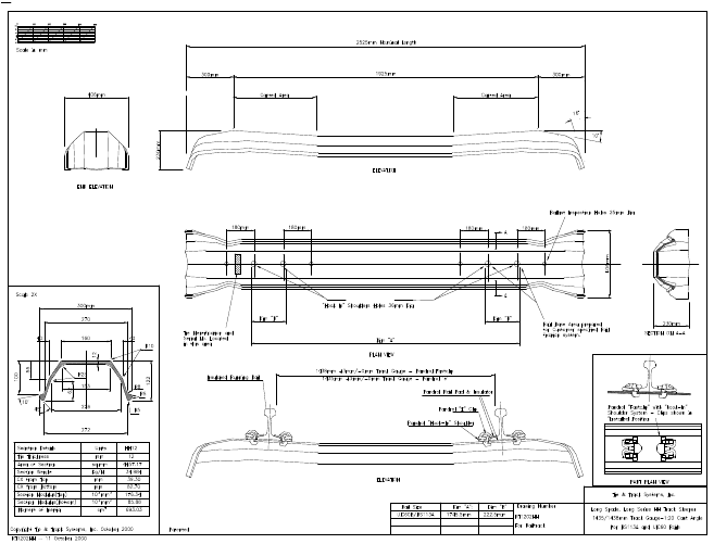
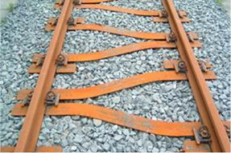
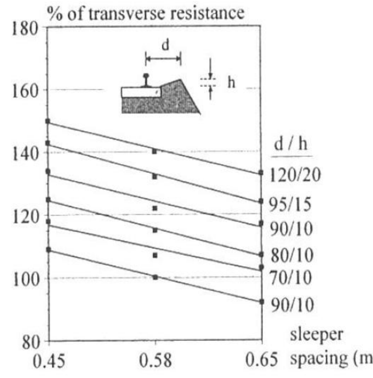
Figure 11.58 compares sleeper spacing together with the specified ballast-profile cases. Because both the support arrangement and test conditions matter, the plotted relative values must not be treated as universal spacing corrections.
The devices in Figure 11.59 increase lateral engagement at the sleepers. Distinguish this transverse action from the longitudinal rail anchors discussed earlier; the two details resist different relative movements.
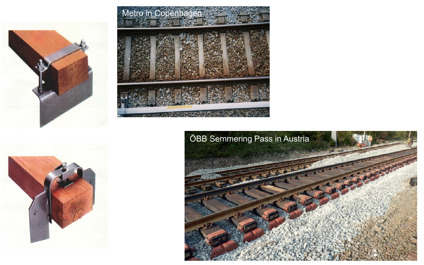
The underside of a BNF friction sleeper has a pronounced profile that engages the ballast. It forces the shear zone down into the crushed stone instead of allowing movement mainly along a smoother sleeper underside. The mechanism uses the ballast’s internal friction and interlock, not just extra sleeper weight. Ballast condition and consolidation remain important [175].
Laboratory tests reported for standard and friction sleepers, together with ERRI/Bane NOR summaries of sleeper-type effects, show that available lateral resistance depends strongly on vertical load and sleeper type [137, 18]. This matters before the simplified \(q=P/R\) equilibrium check is applied, because the resistance used in the check is not a fixed material constant; Figure 11.53 gives representative measured trends.
The special-sleeper examples act through several mechanisms. A profiled underside or scalloped side increases engagement with the ballast; wider end regions and twin blocks change the surfaces mobilising passive ballast resistance; and connected frames or cross-braced twin sleepers increase the interaction between neighbouring supports. The ZSX bending sketches contrast ordinary panels with cross-braced pairs under a transverse load. Pressed-steel and Y-shaped steel sleepers provide further examples of how geometry changes ballast engagement and load distribution. These examples require assessment as complete track systems. The BNF60 field photographs identify a 190 m curve at Oslo S and 201–242 m curves on the Røros Line; those are site examples, not a replacement for the current radius and sleeper requirements. The historical sleeper-type and spacing charts preserve the relative trends reported in the lecture, including their spread, rather than supplying universal resistance multipliers.
Transverse sleeper anchors. These devices engage the ballast to increase resistance to sideways sleeper movement. They are distinct from rail fastenings and from longitudinal rail anchors used to control rail creep. The lecture shows applications in the Copenhagen Metro and on the Semmering route in Austria. Their use is a system-specific measure, not a substitute for an adequate ballast profile.
11.4.4 Ballast Quality and Profile
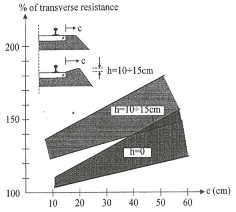
Ballast condition and profile. Angular, durable crushed stone provides interlock; filled cribs mobilise resistance along the sleeper sides; and a supported shoulder restrains the sleeper ends. A wider shoulder or raised shoulder profile can improve resistance, but loosely tipped stone on an unsupported slope does not provide the same confinement. Fouling, drainage problems, particle breakdown and disturbance can all change the behaviour. The ballast grading and prescribed profile must be appropriate to the route, sleeper type and curve radius. See Chapter 3 for the underlying ballast properties.
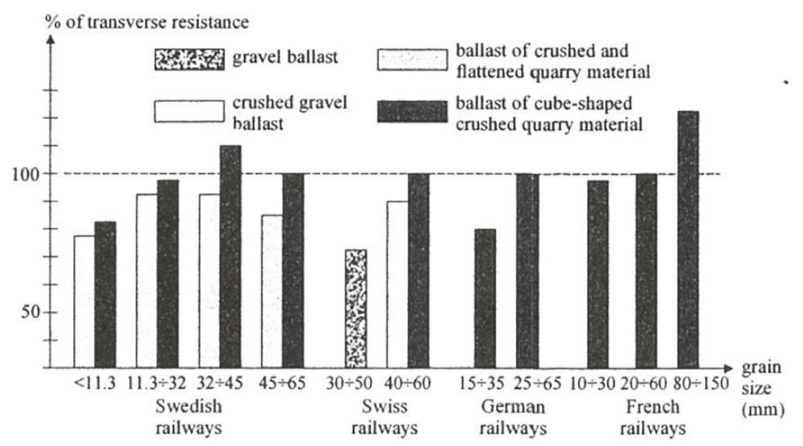
Ballast must also distribute load with suitable resilience and drain water. Here, a clean, porous ballast bed means open voids between durable stones, not weak or highly porous individual particles. Water content, fouling and freezing can alter contact and interlock; a temporarily frozen state must not be treated as permanent consolidation. Cubical, angular particles, suitable grading and resistance to wear help preserve the intended behaviour. The historical material, grading and shoulder charts illustrate these influences under their particular test conditions. A raised crown and a wider shoulder change confinement in different ways, so their effects cannot be reduced to one universal percentage.
The angular particles in Figure 11.60 illustrate the ballast contact network that provides friction and interlock beneath the track. Particle shape is one contribution; profile, compaction and contamination still affect the available resistance.
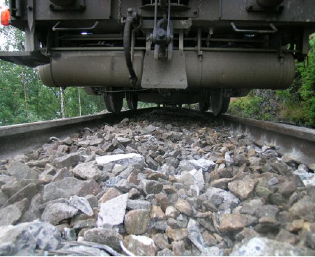
Figure 11.61 compares the historical material and grading cases rather than a single isolated particle-size effect. Read the material descriptions with the curves, and do not substitute these comparisons for current ballast specifications.
In Figure 11.62, shoulder width and crown height are varied within the illustrated test conditions. Their combined effect explains why lateral resistance cannot be inferred from shoulder width alone.
The raised shoulder in Figure 11.63(a) and uncrowned shoulder in 11.63(b) differ at the sleeper ends, where ballast supplies lateral restraint. Compare this shape difference with the preceding test graph without assuming the photographs quantify its benefit.
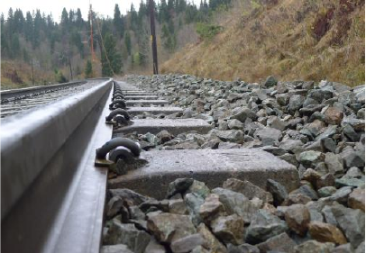
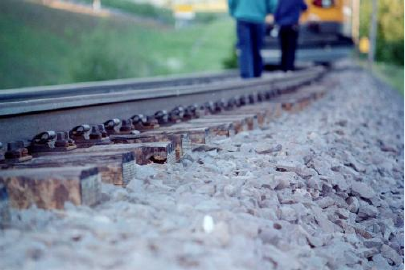
Figure 11.64(a) shows ordinary shoulders, 11.64(b) widens the outer shoulder and 11.64(c) combines widening with a raised crown. The progression identifies where ballast geometry changes; the applicable current profile must still be selected from the requirements stated above.
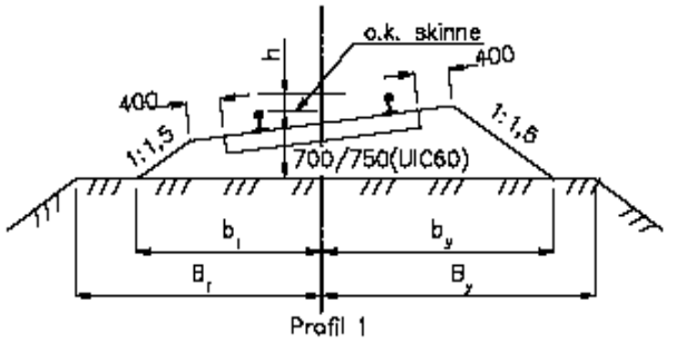
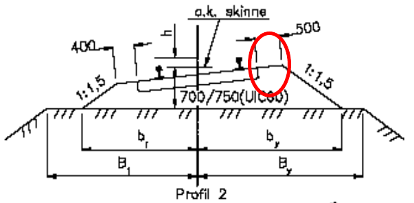
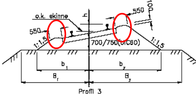
For CWR and jointed rails longer than 30 m, TRV:03458 lists these radius bands (m):
| Profile | Timber | Concrete | BNF60/BNF60+ |
|---|---|---|---|
| 1 | Straight or >500 | Straight or >400 | Straight or >400 |
| 2 | 499–400 | 399–300 | 399–300 |
| 3 | 399–300 | 299–250 | 299–190 |
The minimum radii apply to main tracks and main through tracks at stations. Use the approved profile drawings and requirements [179] for design. TRV:08262 specifies 31.5–63 mm ballast in these tracks, except 22.4–50 mm on the Ofoten Line.
The published table uses integer bands rather than a complete mathematical partition. Resolve exact boundary cases using the applicable approved requirements and drawings.
The broad outer shoulder in Figure 11.65(a) contrasts with the exposed sleeper ends in 11.65(b) and restricted support beside the slope in 11.65(c). These observations direct inspection towards the available ballast volume and confinement at the ends.
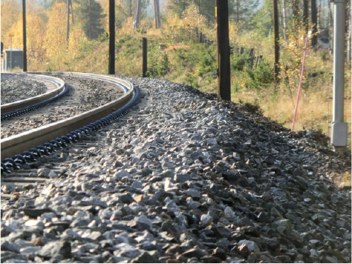
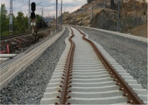
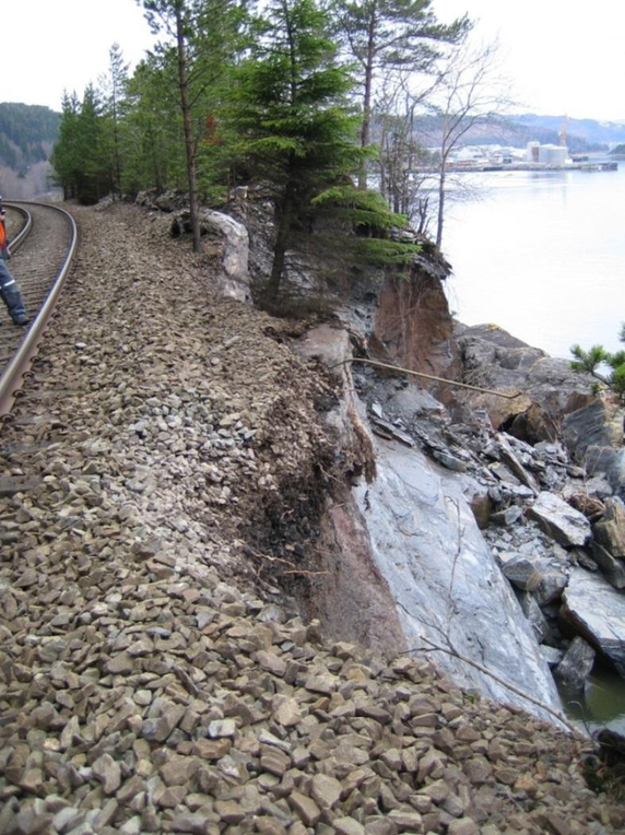
Figure 11.66 brings rail bending, fastening rotation and ballast contact into one track-panel response. A change to one component must therefore be assessed together with the other restraint mechanisms.
Ballast tests must describe particle shape and grading, fines, moisture and whether the ballast is frozen. A resistance measured in one condition cannot automatically be transferred to another, particularly after thawing or disturbance. Ballast depth, shoulder geometry, filled cribs and the degree of consolidation belong to the same assessment.
11.4.5 Tamping, Resistance Curves and Consolidation
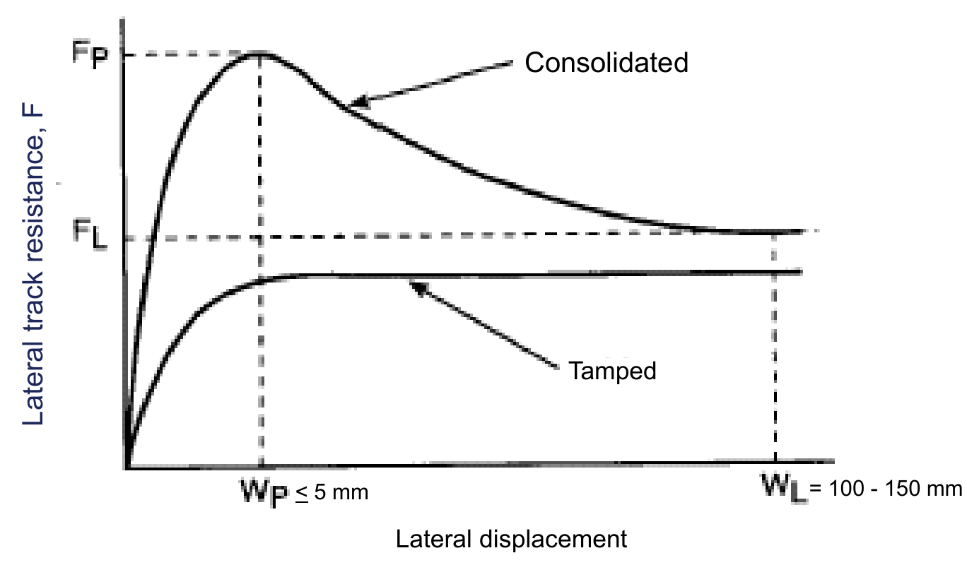
Lateral resistance is a force–displacement relationship, not a single constant. In the lecture’s consolidated-track example, resistance rises quickly to a peak at a small lateral displacement, then falls towards a lower residual resistance as movement increases. Freshly tamped track develops a lower, flatter response because the ballast has been disturbed. The small-displacement peak and the resistance after a large displacement are therefore different inputs to a stability model.
Compare the before-tamping, immediate post-tamping and later measurements in Figure 11.67. They illustrate disturbance and recovery in one panel, not a universally sufficient waiting period before unrestricted operation.
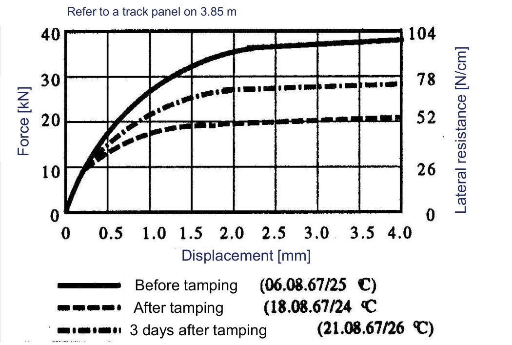
Figure 11.68 distinguishes the initial resistance peak from the residual response at larger displacement. The value used in a model must correspond to the relevant displacement state; plotted displacement is not an allowable alignment defect.
The curves in Figure 11.69 relate recovery to accumulated traffic in the historical examples. Recovery depends on the disturbed ballast and loading conditions, so traffic tonnage alone is not a universal reopening criterion.
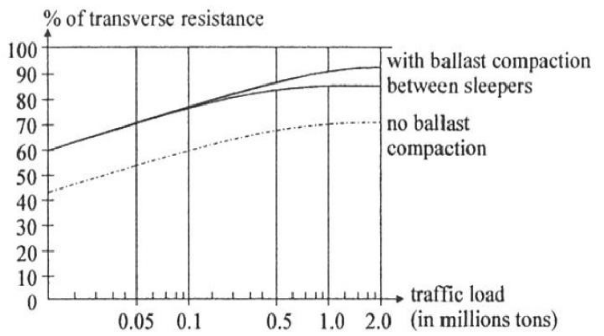
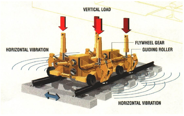
Figure 11.70(a) shows vertical loading combined with horizontal vibration, while 11.70(b) places that working principle in the stabilising machine. The process aims to settle ballast contacts deliberately rather than relying only on subsequent train passages.
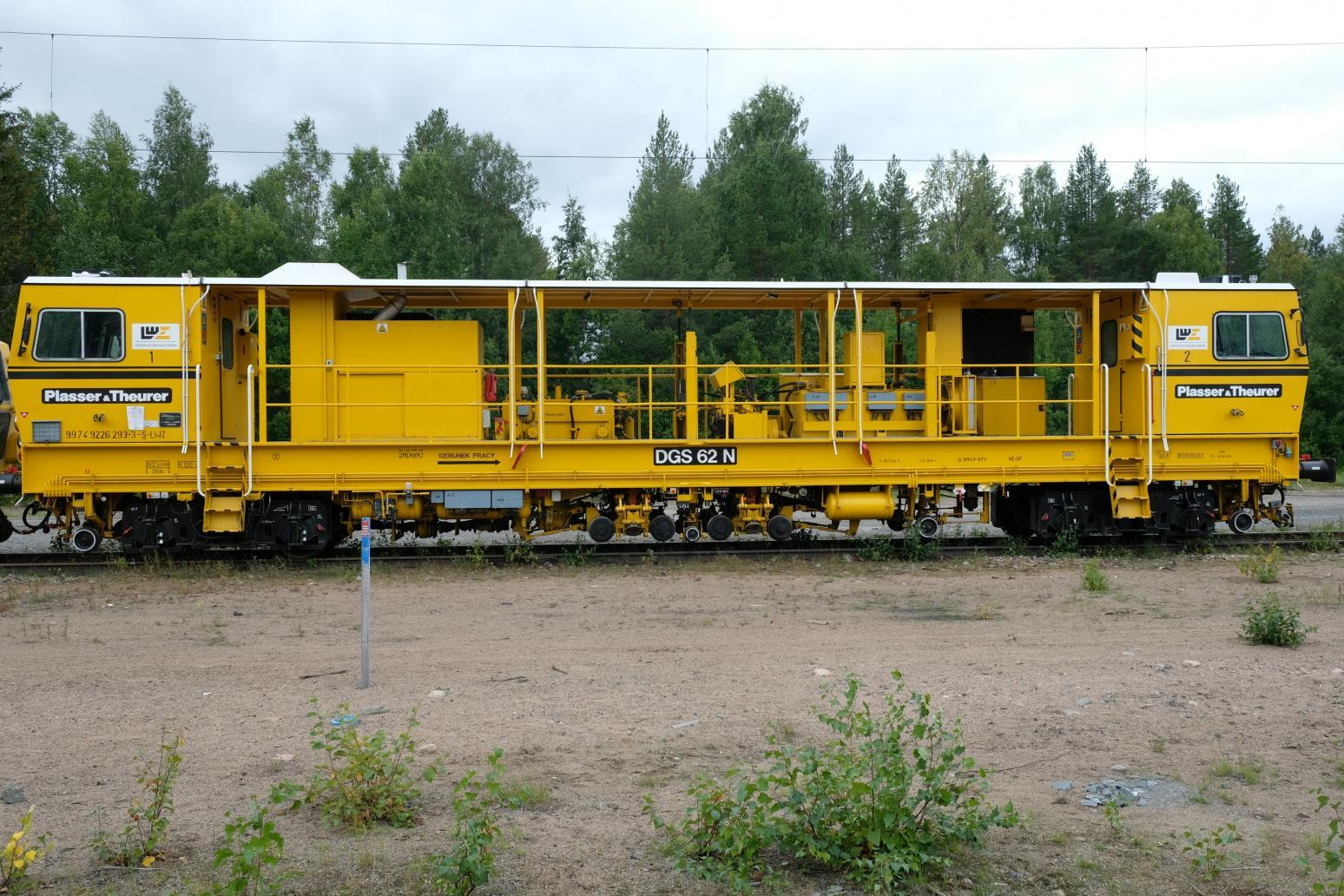
The marked unit in Figure 11.71(a) is shown more closely in 11.71(b). Its action beside the sleeper ends targets a different contact region from the tamping tools beneath the rail seats.
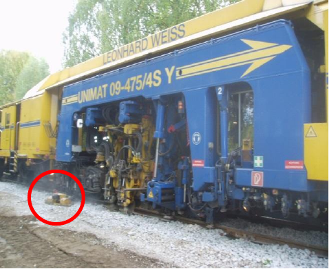
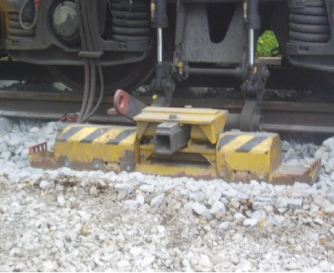
Figure 11.72 shows another position of the sleeper-end compactor. Relate the tool position to the ballast beside the sleeper end when distinguishing its action from under-sleeper tamping.
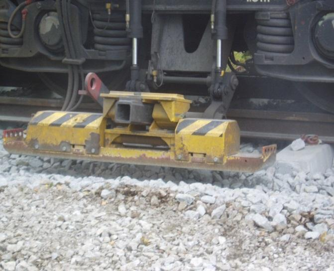
Figure 11.73 compares the disturbance associated with different work types. The percentages help explain why post-work stability measures must match the operation performed, but are not operational release limits.
When comparing measurements, check the displacement at which the resistance was read and whether the result refers to one sleeper, one rail or a length of complete track panel. Dividing a test force by the tested panel length gives an average resistance per metre, but only for that test configuration. A peak measured on consolidated track should not be used unchanged for recently tamped track or for an analysis requiring residual resistance.
Traffic consolidation progressively changes the curve after maintenance. The lecture’s before-and-after tamping tests and traffic-tonnage examples show the mechanism; neither a fixed waiting time nor one percentage recovery describes every site. The applicable work and stabilisation requirements still govern reopening and speed restrictions.
After tamping, lateral resistance can be substantially lower than before the work. Recovery occurs as ballast contacts settle and interlock under loading. Three mechanisms are distinguished in the lecture:
- Traffic consolidation progressively restores restraint under repeated train loads.
- Sleeper-end compaction acts locally on the ballast beside the sleeper ends.
- Dynamic track stabilisation applies controlled loading and vibration through the track panel after tamping.
Bane NOR’s current maintenance rules use 100,000 gross tonnes (0.1 MGT) as the full-stabilisation convention. They credit a dynamic track stabiliser with that equivalent effect when it is used after each tamping, and a shoulder vibrator with 25,000 gross tonnes. These are regulatory conventions; actual physical recovery still depends on the track and work performed. The machine arrangement is shown in Chapter 5, Figure 5.13.
Stabilisation credit is not a general clearance to unrestricted speed. The ballast profile, neutralisation, geometry and applicable post-work restrictions must also be satisfied. For example, DTS is prohibited over ballast mats, and its use on bridges and other structures requires the specified analysis approved by Bane NOR, together with an assessment of the structure’s current condition. See Bane NOR’s CWR maintenance requirements [6], including TRV:05103, 05108 and 05111.
The measured curves in the lecture refer to a 3.85 m track panel. Their two vertical scales describe the same result: 40 kN over that length is about 104 N/cm of track. The curves compare the condition before tamping, immediately after tamping and three days later. Recovery after three days is an observation from that case, not a waiting-time rule. The traffic-recovery graph attributed to V. Profillidis (1987) [175] similarly distinguishes compaction between sleepers from recovery without that treatment.
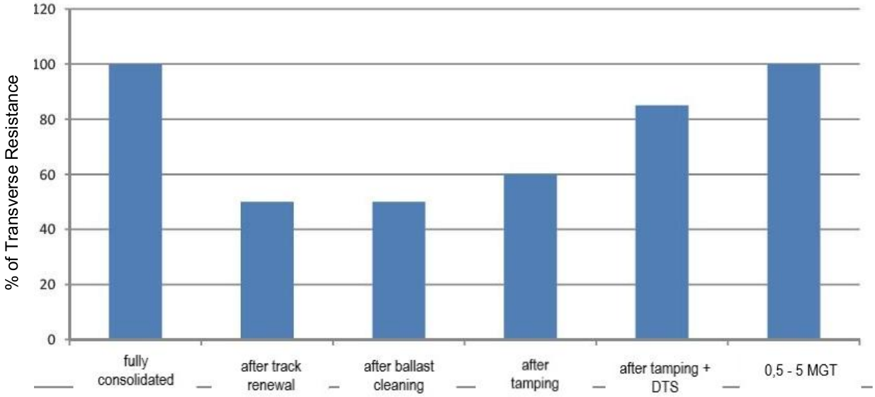
The lecture gives several different descriptions of consolidation. Its text places 100,000 gross tonnes alongside a physical recovery range of 1–2 million gross tonnes. A separate illustrative bar chart uses fully consolidated track as 100%, then shows about 50% after track renewal, 50% after ballast cleaning, 60% after tamping and 85% after tamping with DTS; its final 100% bar is labelled 0.5–5 million gross tonnes. These are different comparisons with incompletely stated conditions. They do not replace the current Bane NOR stabilisation convention, and the 85% bar must not be confused with the separate 50–80% relative improvement quoted elsewhere. Physical recovery and regulatory credit are different quantities.
11.4.6 Corrugation and Sleeper Deterioration
Two deterioration chains illustrate how observations connect to these mechanisms. Rail corrugation increases vibration, which can disturb ballast contacts; grinding addresses the excitation, while the ballast condition still needs assessment. Cracked concrete sleepers, including damage associated with alkali reactions, can reduce support and fastening effectiveness; replacing defective sleepers addresses a different weakness. Neither repair by itself restores an incorrect stress-free temperature.
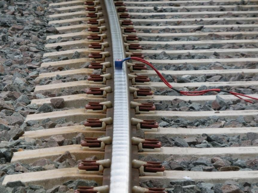
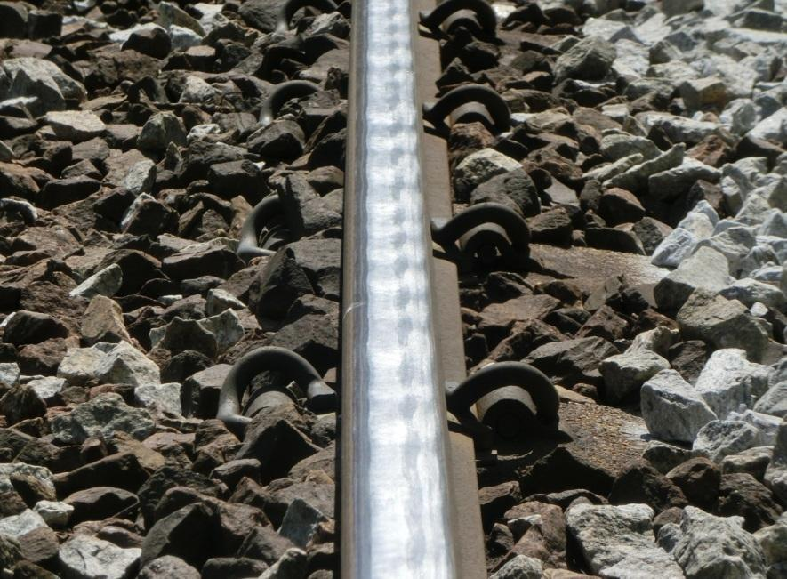
Figure 11.74(a) places the corrugation in the track and 11.74(b) shows the rail-surface detail. The periodic input can generate vibration, linking a running-surface condition to the disturbance of ballast contacts discussed here.
The cracked sleepers in Figure 11.75(a) motivate condition assessment; the handling operation in 11.75(b) shows that replacement also disturbs the supporting track system. The photograph cannot by itself establish an alkali-reaction diagnosis.
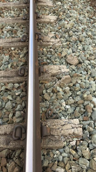
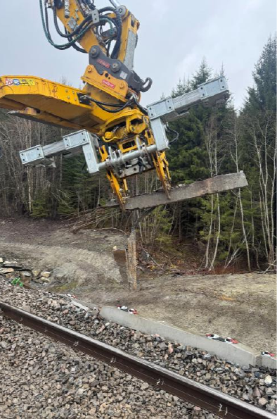
11.4.7 Dynamic Uplift
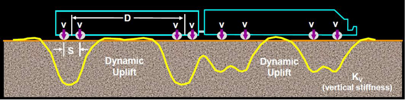
A critical but often underestimated factor is dynamic uplift: the vertical unloading of the track that occurs in the track section ahead of and behind an axle due to the wave of elastic deflection. Figure 11.77 links this axle-induced vertical movement to the temporary reduction in dynamic lateral resistance.
Figure 11.76 contrasts locally increased loading beneath an axle with unloading in the adjacent lifting wave. The lateral resistance under a passing vehicle therefore need not equal the unloaded static resistance everywhere along the panel.
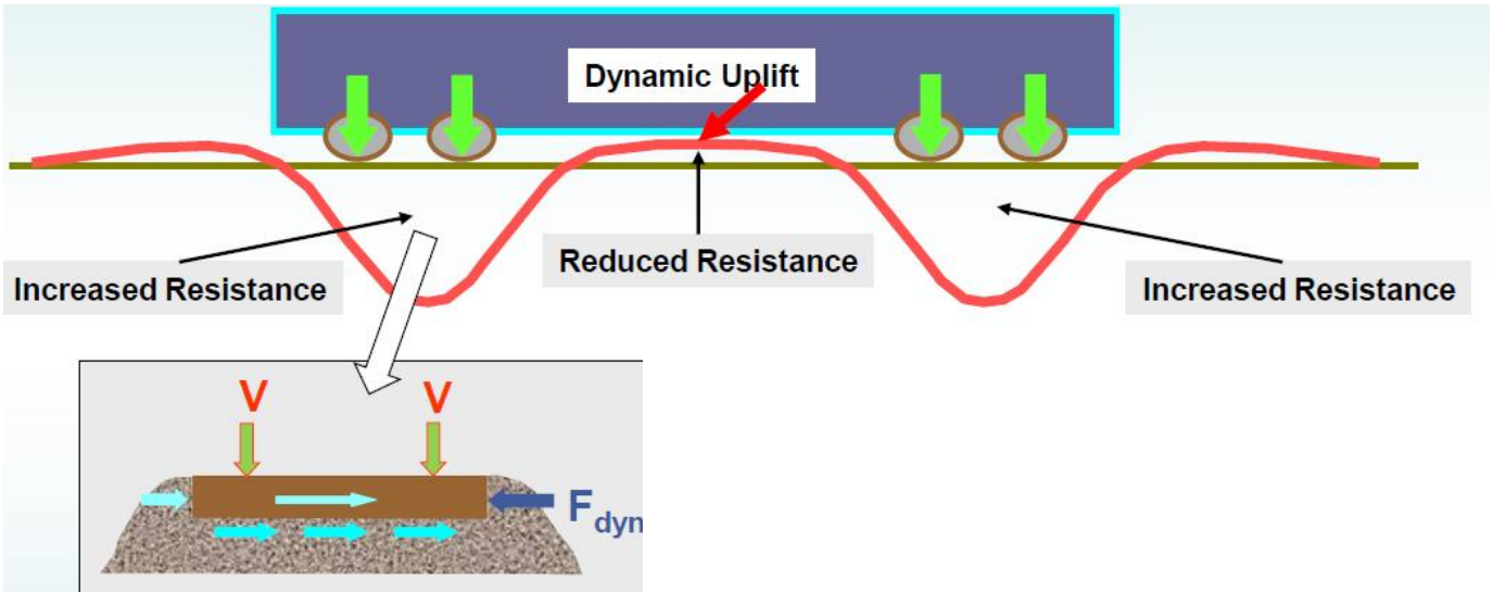
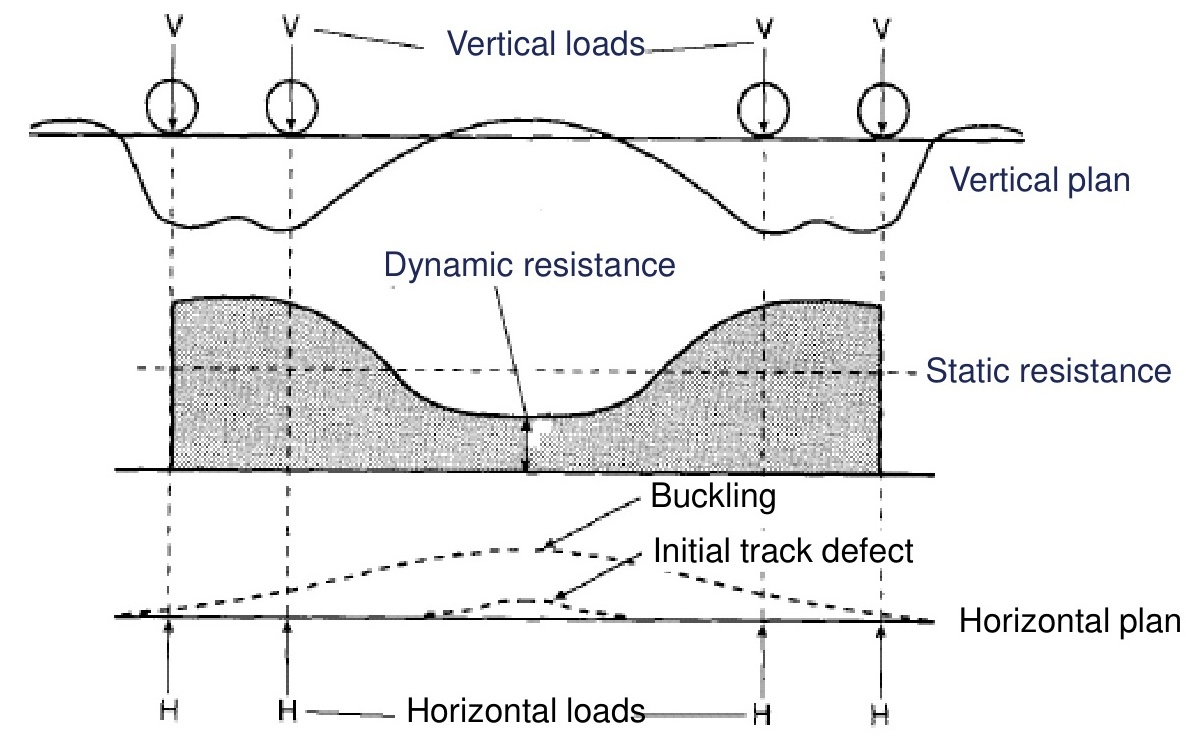
In the simplified model used by Kish and colleagues, the resistance under vertical loading is related to the static sleeper resistance [122]:
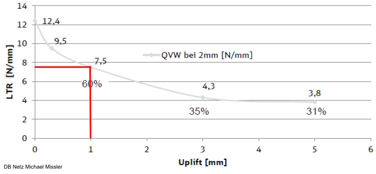
Here \(F_D\) is the loaded sleeper's lateral resistance, \(F_S\) its static resistance before the passing vehicle adds or removes vertical load, and \(\mu\) an apparent sleeper–ballast friction coefficient. The incremental vertical reaction \(V\) is positive for added loading and negative for unloading. The static contribution already includes self-weight, so that weight must not be added again through \(V\). All force quantities refer to the same sleeper. This linear approximation is bounded by loss of ballast contact; it cannot be extended to tensile contact forces. Uplift can substantially reduce resistance, as illustrated by the lecture's 1 mm example.
The unloading pattern depends on bogie spacing, axle spacing, axle load and vertical track stiffness. The rail can be pressed down beneath one axle while adjacent sleepers are partly unloaded. Thus a heavy train does not increase lateral resistance uniformly along its length. An existing lateral defect may grow where unloading and lateral forces coincide. The lecture uses this interaction to explain why train speed and the post-maintenance condition matter, even when a static radial-equilibrium calculation appears satisfactory.
Figure 11.78 places the loading and unloading zones in relation to axle and bogie spacing. Use it to distinguish vehicle geometry from the track's vertical stiffness, both of which influence the uplift pattern.
The separate curve attributed to DB Netz, Michael Missler, reports lateral resistance at 2 mm lateral displacement. Its plotted values fall from 12.4 N/mm at zero uplift to 7.5 N/mm at 1 mm uplift, 4.3 N/mm at 3 mm and 3.8 N/mm at 5 mm. The 1 mm point retains about 60% of the initial value, which explains the lecture's approximate 40% reduction statement. The test conditions are not fully specified, so the curve is an example rather than a universal uplift law. Train speed, train length and repeated loading influence the dynamic excitation as well as the instantaneous unloading; they cannot be replaced by a single static resistance multiplier.
Figure 11.79 demonstrates sensitivity of the illustrated lateral resistance to small uplift. The plotted reduction belongs to this example and measurement displacement; it must not be applied as a universal correction to another track.
11.4.8 Summary of Influences on Resistance
Maintenance actions can temporarily reduce the sleeper–ballast contribution to LTR, while consolidation and stabilisation gradually restore resistance. Table 11.7 reproduces the lecture’s illustrative influence values. Their interpretation depends on track class, ballast condition, sleeper type and measurement method; the related Bane NOR guidance and lateral-resistance literature discuss these mechanisms [18, 129].
The numerical values are taken from the lecture’s influence summary [175]. The percentages refer to different comparisons and test conditions. They must not be added together or used as universal correction factors.
| Factor | Effect on LTR | Comment |
|---|---|---|
| Rail bending stiffness \(I_y\) | \(-5\) to \(+4\) % | Usually secondary to ballast and sleepers |
| Fastening torsional resistance | \(+10\) to \(+20\) % | Depends on clamp condition and rail-seat friction |
| Sleeper material: concrete vs. timber | \(+60\) % | Dominant factor |
| Reduced sleeper spacing | \(+5\) to \(+10\) % | More sleeper–ballast contact per metre |
| Tamping | Reduction depends on the conditions | See the measured before/after curves |
| Ballast cleaning | \(-70\) % | Fines removal |
| Track adjustment / ballast disturbance | \(-50\) to \(-60\) % | Especially critical in warm weather |
| Ballast compaction | \(+10\) to \(+20\) % | Illustrative lecture range; method and condition matter |
| Dynamic track stabiliser (DTS) | \(+50\) to \(+80\) % | Lecture estimate; the comparison baseline is not specified |
| Transverse sleeper anchors | \(+30\) to \(+40\) % | Additional sleeper–ballast restraint, not fastening clips |
| Crushed vs. rounded ballast | \(+30\) % | Interlock effect |
| Reduced ballast shoulder | \(-10\) to \(-50\) % | Geometry-dependent |
| Insufficient ballast in the cribs | Reduction of up to 50% | Reduced restraint at the sleeper sides |
| Dynamic uplift (passing axle) | \(-30\) % | Transient unloading |
The lecture also lists splintery or flaky ballast particles with a tentative “−10%?” effect. The question mark is significant: no test basis or comparison condition is supplied. Particle shape should be considered when assessing interlock, but this tentative figure is not a design reduction factor.
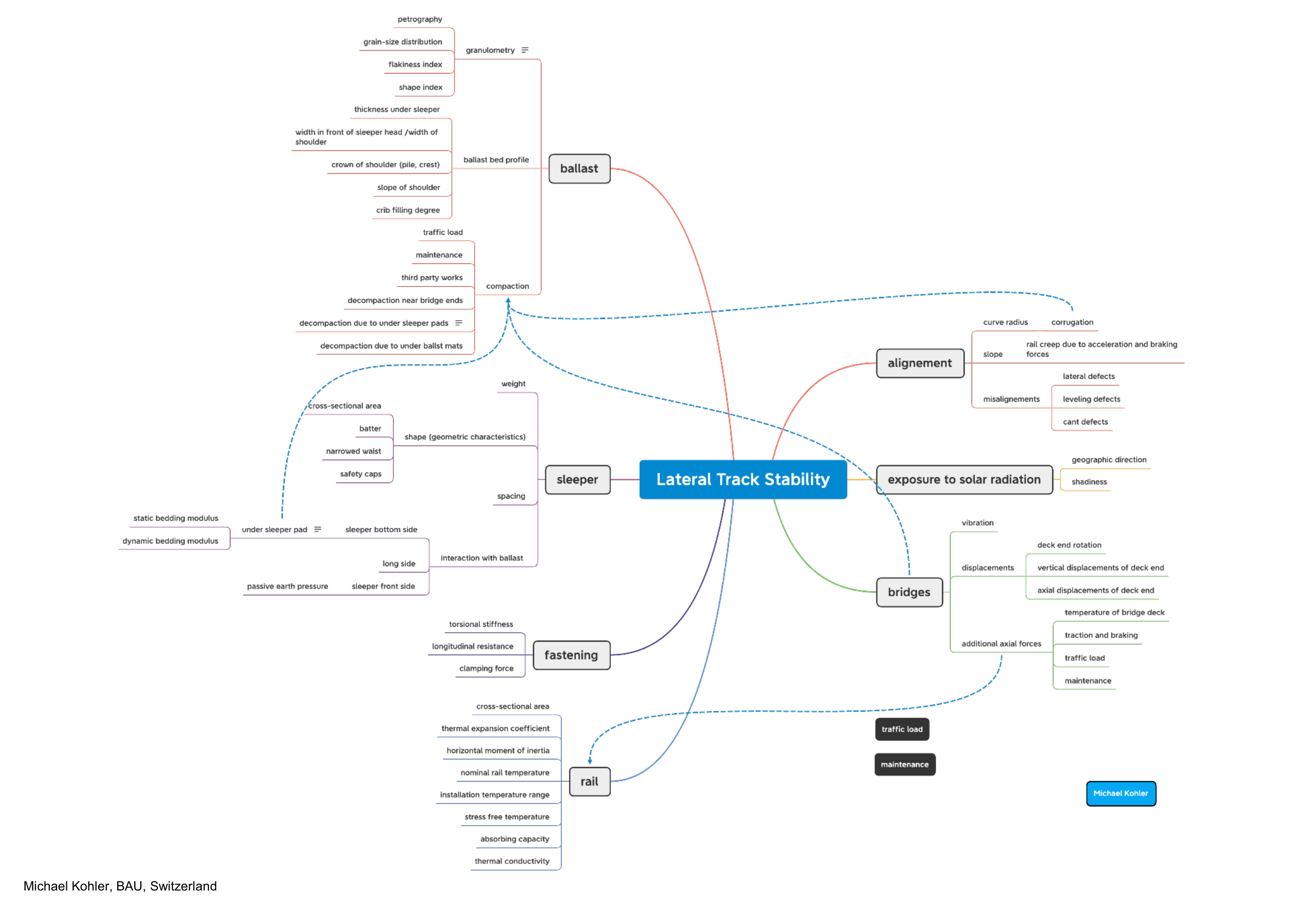
Michael Kohler's parameter map summarises the main influences. It groups the assessment into the following interacting parts:
- Ballast: rock type, particle-size distribution, flakiness and shape; ballast thickness; shoulder width, crown and slope; crib filling; and compaction affected by traffic, maintenance, third-party work and local disturbance near bridge ends. It also identifies under-sleeper pads and under-ballast mats as changes to the support system whose effects need assessment.
- Sleepers: weight, cross-section, taper and waist shape, transverse anchors and spacing; underside contact, static and dynamic pad bedding properties; friction along the long sides and passive resistance at the ends.
- Fastenings: rotational stiffness, longitudinal resistance and clamping force.
- Rails: section area, thermal-expansion coefficient and lateral bending inertia; target, installation and actual stress-free temperatures; and thermal behaviour, including absorption and heat conduction.
- Alignment and exposure: curve radius, gradient, corrugation, rail creep under traction or braking, lateral and vertical alignment defects, cant defects, geographic orientation and shading.
- Bridges: vibration; rotation and vertical or longitudinal movement of the deck ends; and extra forces associated with deck temperature, traction, braking, traffic and maintenance.
The connecting lines show that these parts interact. The map supplies an inspection framework, not a list of independent numerical penalties.
Follow the branches in Figure 11.80 from rail force and geometry to the supporting components and their condition. The map is useful as an investigation checklist because these influences interact, rather than acting as independent correction factors.
11.4.9 Required Resistance in a Curve
Figure 11.81 relates axial force in curved track to radial action. Keep force and resistance on the same one-rail or whole-track basis when applying the equilibrium; mixing these bases creates a factor-of-two error.
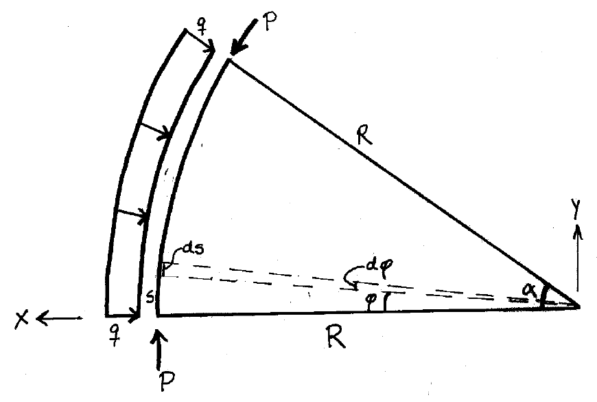
The relation \(q=P/R\) expresses the lateral resistance per unit track length needed to balance a compressive rail force in a curve of radius \(R\). It is a curved-rail equilibrium check, not a complete buckling criterion. Buckling resistance also depends on alignment imperfections, bending stiffness, restraint and boundary conditions, as discussed in Section 11.5.
Take a short curved track-panel segment with a half-angle \(\theta\). The radial components of the two end forces sum to \(2P_\mathrm{tot}\sin\theta\). The resultant of a uniform radial resistance along the same arc is \(2q_\mathrm{tot}R\sin\theta\). Equating them gives \(q_\mathrm{tot}=P_\mathrm{tot}/R\). This derivation assumes a prescribed curved alignment; it does not test whether an imperfect track panel will remain stable after a disturbance.
Here \(P_\mathrm{tot}\) is the total compressive force in the two rails and \(q_\mathrm{tot}\) is the total lateral track resistance per metre for the track panel. If a per-rail resistance is used instead, use \(P_\mathrm{rail}\) and \(q_\mathrm{rail}\) on both sides of the same check. The result is physically the same, but mixing total force with per-rail resistance gives an erroneous factor of two. This formula shows that the tightest curves require the highest LTR [68, 164]. The applicable ballast profile, sleeper type and spacing therefore depend on curve radius and track category. Friction sleepers are one specified option; they are not required in every curve. Departures from mandatory minimum radii require an approved exemption under TRV:00188, not only additional physical measures.
Worked example.
Assume a curve with \(R=400\) m and a total compressive force in both rails of \(P_\mathrm{tot}=720\) kN. The required total lateral resistance is
If the pre-tamping total LTR is 10 kN/m and tamping reduces it to 45 %, the available total resistance is \(0.45\times10=4.5\) kN/m. Since \(4.5>1.8\) kN/m, the simple equilibrium check is satisfied. Speed restrictions may still be needed because dynamic uplift, alignment defects, and freshly disturbed ballast are not included in the check.
The lecture also derives the radial balance by resolving forces along a fixed axis. To avoid confusing its geometric angle with the thermal-expansion coefficient, call the sector angle \(\theta\). For an arc coordinate \(s=R\varphi\), \(ds=R\,d\varphi\), and the component of uniform radial resistance is
The end-force component is \(P_\mathrm{tot}\sin\theta\), giving the same result \(q_\mathrm{tot}=P_\mathrm{tot}/R\). If a projected coordinate \(S=R\sin\varphi\) is used instead, then \(dS=R\cos\varphi\,d\varphi\). Arc length and projected length must not be interchanged; the lecture uses closely similar symbols for them.
11.5 Track Buckling
CWR can buckle laterally under high compressive force. The following definition classifies a buckling event; the limits requiring intervention can be stricter.
11.5.1 Consequences and Field Measurement
Track buckling is particularly dangerous because:
-
It presents a high risk of derailment
-
It is very difficult to predict because continuous, direct in-service measurement of rail force is not normally available
-
A passing train can trigger the buckling
Track buckling is defined by Bane NOR as: a lateral displacement of the track more than 25 mm measured by a chord of 10 m, caused by compressive longitudinal forces in the rails [50]. This is a definition of the failure, not an allowable alignment limit. TRV:05051 gives class-dependent D1 immediate-action limits of 10–22 mm; faults can therefore require intervention before reaching the buckling definition.
On a curve, compare the measured versine with the established alignment. The ordinary versine caused by the curve itself is not a buckling displacement. The lecture’s measurement example concerns the additional lateral deviation, rather than the total offset from the chord. Figure 11.84 shows the field measurement principle for identifying the lateral arch over the 10 m chord.
The deformed track in Figure 11.82(a) illustrates the geometry hazard, while 11.82(b) illustrates the possible seriousness of a derailment. The second photograph is not evidence that buckling caused that particular accident.
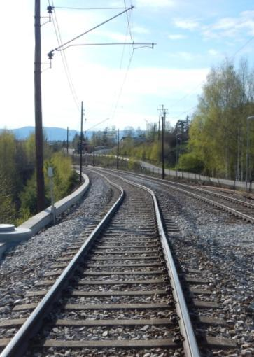
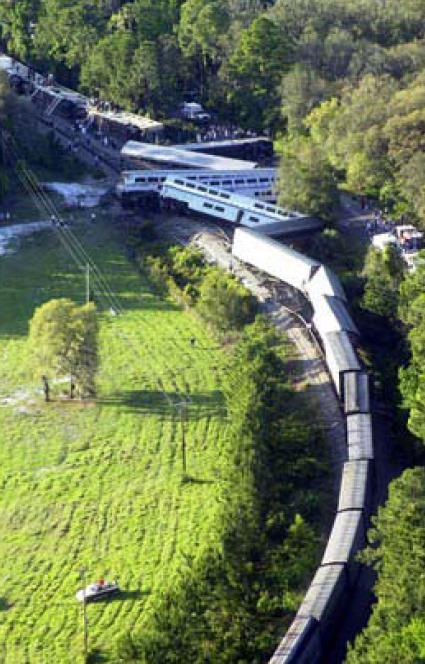
Figure 11.83 defines the additional lateral displacement against a 10 m chord. The chord supplies a repeatable measurement reference; the definition is not permission to leave a smaller deformation in service.
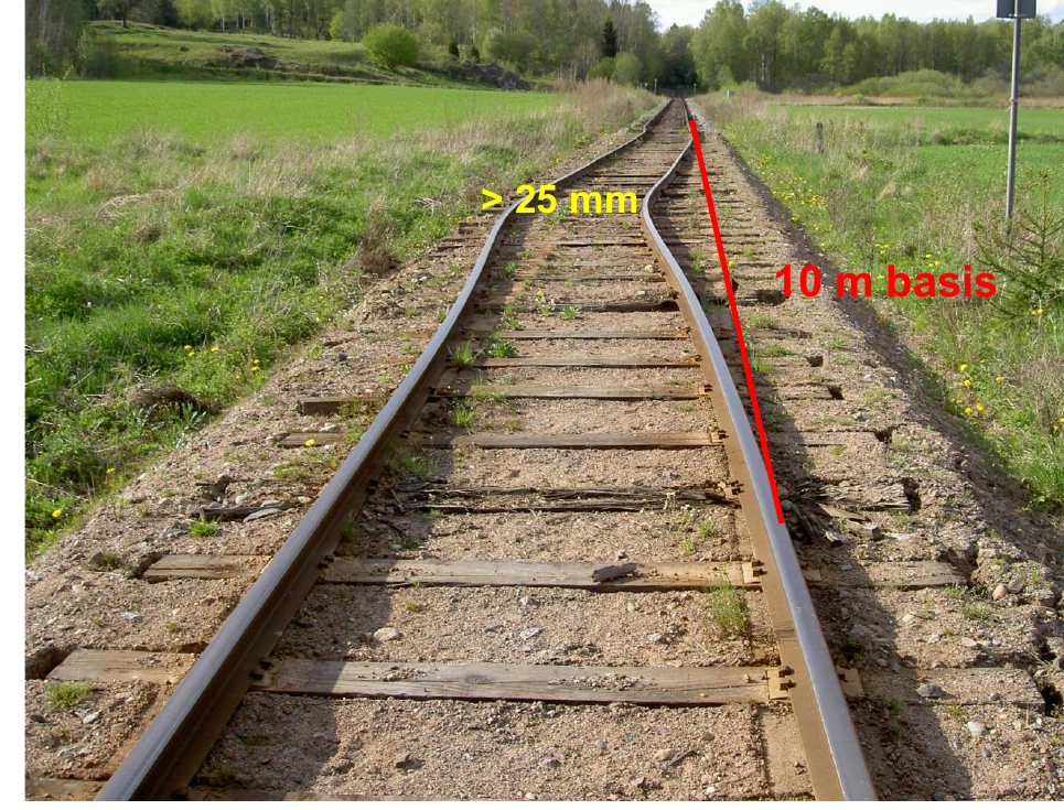
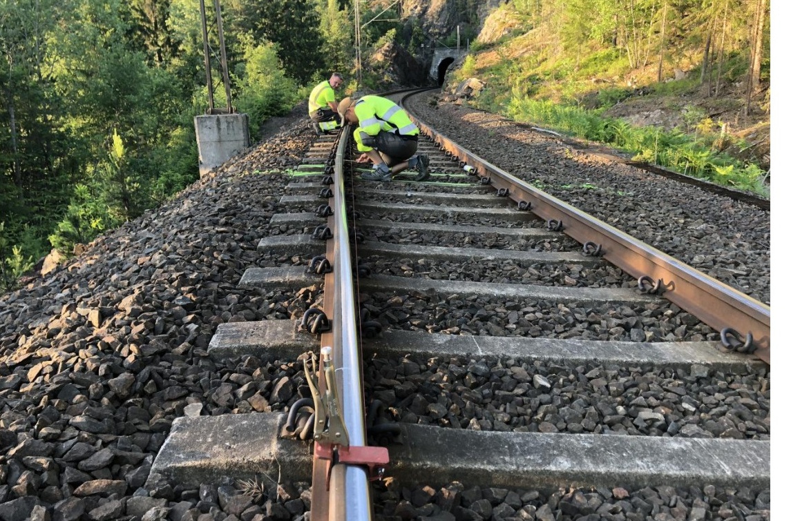
The close view in Figure 11.85 shows how a chord measurement is made during investigation. Record the reference length and measurement location together with the displacement so observations can be compared consistently.
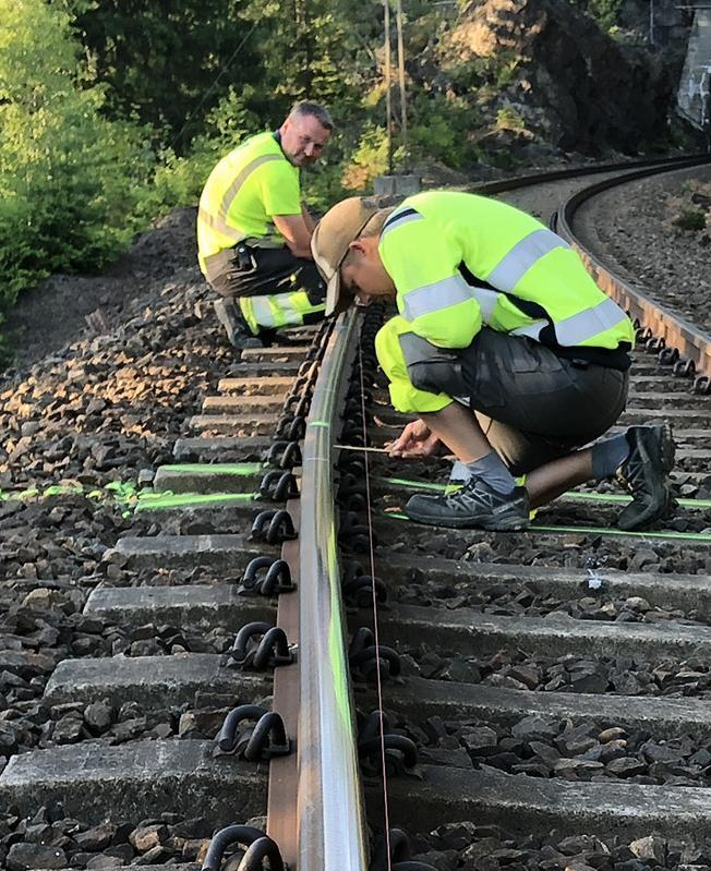
11.5.2 Causes and Alignment Defects
Elements that reduce LTR or increase compressive forces:
-
Too small ballast profile (narrow shoulders, insufficient crib filling)
-
Fouled ballast (reduced internal friction)
-
Track maintenance work (tamping, ballast cleaning), critical in warm weather
-
Dynamic uplift from passing trains, which can substantially reduce LTR; see the measured example in Section 11.4.7
-
Vibrations from trains loosening ballast (rail corrugation)
-
Track geometry defects (misalignments, settlement-induced defects)
-
Loose or worn fastenings, cracked concrete sleepers
-
Lateral shift during tamping at low temperatures
-
Rail creep changing the stress-free temperature
-
Insufficient track neutralization
The shape of an alignment defect matters as well as its maximum offset. Defect amplitude and wavelength determine the local curvature and the bending needed to deform the panel. Abrupt changes in restraint, such as a turnout or a transition between concrete and timber sleepers, can concentrate movement and force. A small isolated measurement should therefore be interpreted together with the surrounding alignment and track construction.
The small shoulder in Figure 11.86(a) and narrow formation in 11.86(b) constrain the ballast available at sleeper ends. These are separate inspection observations that can both limit lateral support.
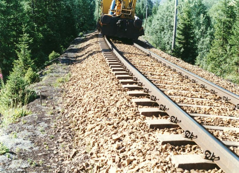
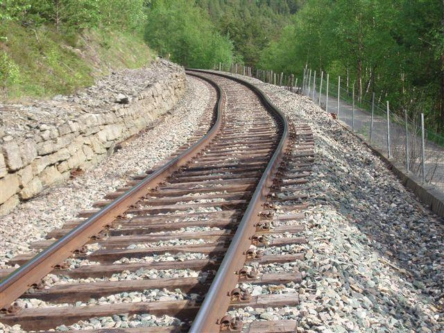
Compare the deposits in Figure 11.87(a) and near the sleepers in 11.87(b) with the localised spots in 11.87(c) and crib deposits in 11.87(d). Their distribution helps target investigation of water and fines movement, but appearance alone does not identify the source material or drainage fault.
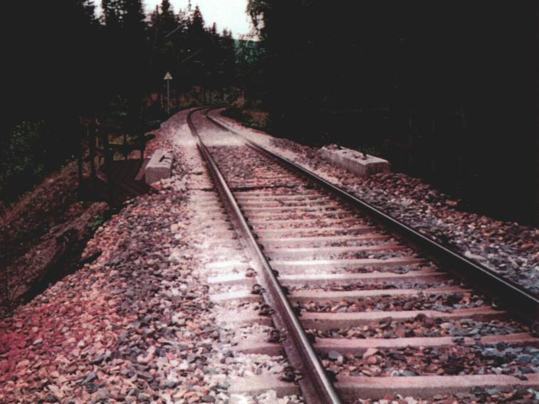
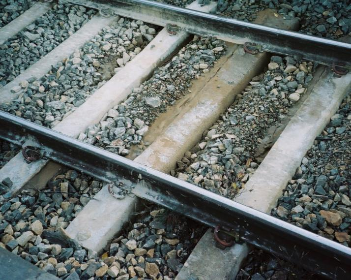
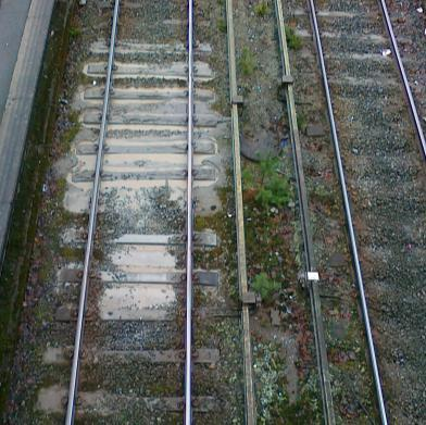
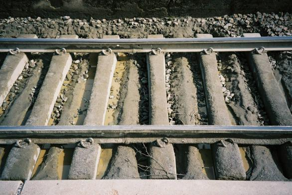
The alignment variations in Figure 11.88(a) and 11.88(b) occur near the changes in restraint identified in the examples. Such transitions deserve measured investigation of geometry and longitudinal movement rather than an assumed uniform rail force.
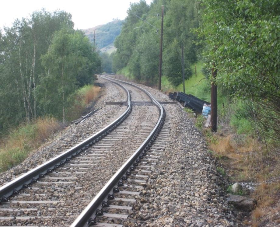
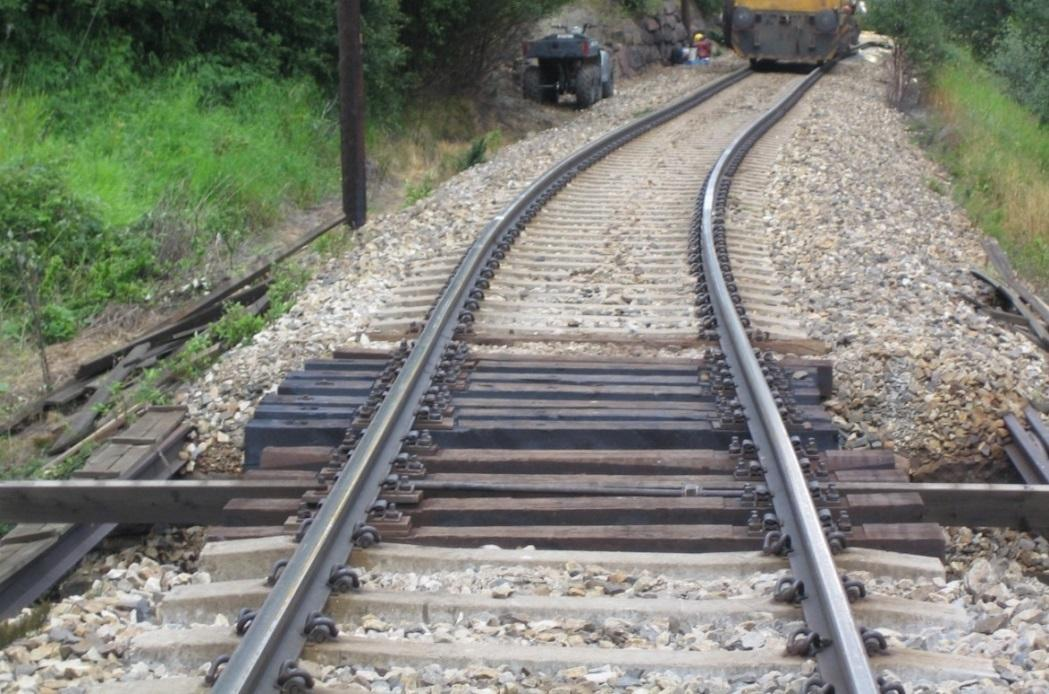
Figure 11.89 distinguishes defect amplitude from wavelength. Two defects with the same maximum offset can have different shapes and stability consequences, so a single peak displacement is not a complete geometric description.
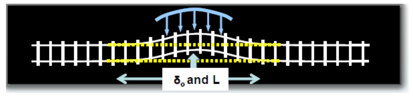
The field examples add several inspection details. A narrow formation can prevent a sufficient ballast shoulder even where the ballast itself is sound. Light deposits at pumping sleepers indicate transport of fines and require investigation of water, support and drainage; colour alone does not determine the mechanism. Poor drainage and settlements can create geometry defects. Level crossings, bridges and turnouts are examples of changes in restraint where alignment and force distribution need particular attention.
The lecture's phrase “tension peaks” means local peaks in axial force or stress here; summer buckling is associated with compression. Its examples include weak or rotten timber sleepers, worn fastenings, transitions between sleeper types, inadequate position references, and small expansion gaps in adjoining jointed track. If an expansion gap closes during heating, the load path changes. Lateral movement during tamping can matter at both low and high rail temperatures. Long concrete bridges are another interaction case, but the lecture's approximate 50–100 m length description is not a universal threshold for extra force or an expansion-device rule.
Figure 11.90(a) combines a turnout with a sleeper-type transition; 11.90(b) illustrates the rail-creep example. Use the visible transitions to formulate inspection questions about restraint and movement, not to calculate an axial force from the images.
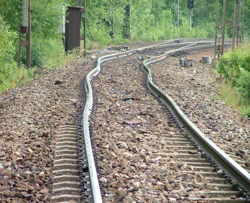
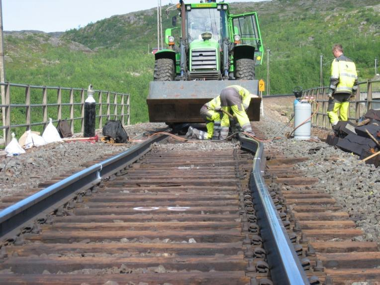
11.5.3 Critical Rail Temperature
The Meier model estimates a critical temperature rise using idealised track geometry and lateral resistance. The curved-track expression below is given in Bane NOR’s teaching material, Eq. 6.7 [18]. It is a model for studying stability, not an allowable operating or work temperature. The equivalent track inertia must represent the actual track panel and its fastenings; simply doubling the rail’s lateral inertia is an explicit simplifying assumption, not a general calibration rule.
The model returns a temperature increase above the actual stress-free state. The corresponding absolute rail temperature is \(T_\mathrm{cr}=T_{sf}+\Delta t_\mathrm{cr}\). A calculated rise of \(40\,\mathrm{K}\) and an absolute rail temperature of \(40\,^\circ\mathrm{C}\) are therefore different quantities.
The two lecture sketches use different assumed deformation shapes. The tangent-track sketch has opposite lateral lobes over a length divided into thirds; the curved-track sketch has an outward arch. These are separate approximations: with unit correction factors, letting the curve radius tend to infinity in the curved expression gives a square-root coefficient of 16, whereas the tangent expression uses 8.7. The two expressions therefore do not merge into one formula in that limit. Their different assumptions must be retained when interpreting the model results.
Figure 11.91 defines the assumed tangent-track deformation shape used by the Meier approximation. Its geometric assumptions are part of the model and should be checked before transferring a result to an observed field defect.
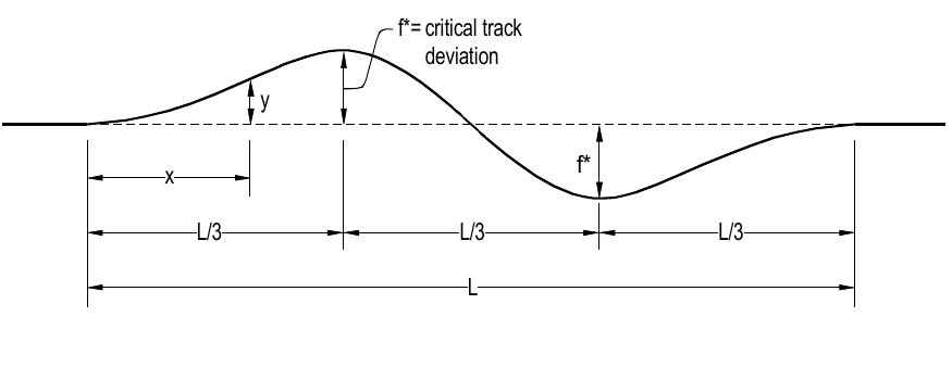
For tangent track:
Identify radius, deformation length and amplitude in Figure 11.92 before using the curved-track expression. The assumed outward shape differs from the tangent-track model and must not be reduced to amplitude alone.
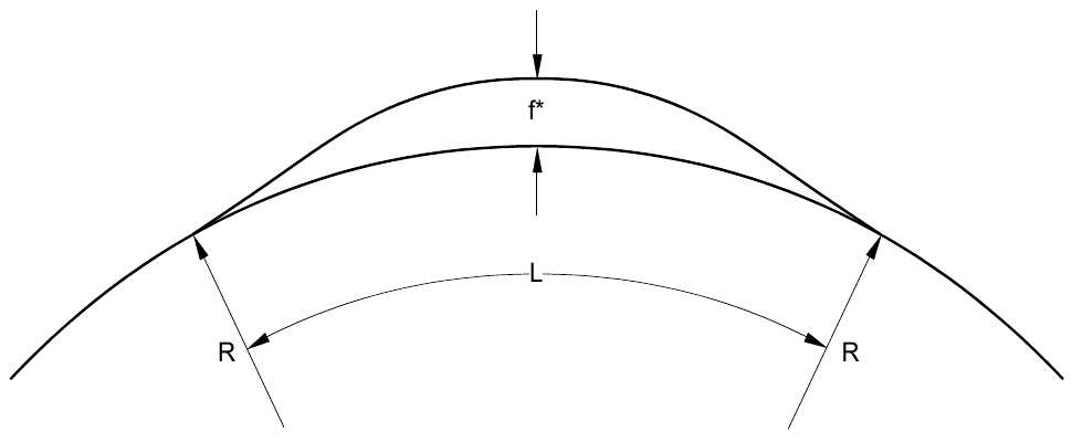
For curved track:
The lecture uses whole-track quantities: \(F=2A\) is the combined area of both rails, \(J\) is the equivalent lateral moment of inertia of the track panel, and \(w\) is the total lateral ballast resistance per unit track length [\(\mathrm{N\,cm^{-1}}\)]. In these teaching calculations, \(f^*\) is an assumed lateral-deviation amplitude, illustrated as 1.5–2.5 cm in the lecture; \(k_1\) accounts for ballast consolidation and \(k_2\) for dynamic unloading, each illustrated over 0.5–1.0. These ranges are model assumptions, not acceptance limits. Use positive \(F,J,E,\alpha,w,f^*\) and, for curved track, \(R\), with consistent centimetre–Newton units. A zero model amplitude \(f^*\) or zero radius is outside these expressions' domain. \(J\) represents lateral bending stiffness; substituting the much larger vertical rail inertia would overestimate the critical temperature. Do not apply a reduction again through \(k_1\) or \(k_2\) if the same effect is already included in \(w\). Figure 11.93 illustrates the radius and misalignment trends for a separate parameter set.
The lecture's notation is not uniform: the tangent-track sketch labels \(f^*\) as a critical track deviation, while the parameter slide calls \(f\) an initiating or estimated misalignment. Those concepts are not generally interchangeable. Here the examples treat \(f^*\) as the stated input to the approximate model; it is neither a measured defect inferred from the drawing nor an allowable geometry deviation. The original model derivation would be needed to reconcile the source terminology fully.
Worked example.
For an illustrative track using legacy UIC60 geometry in a 500 m radius curve with \(q_\mathrm{rail}=6\) kN/m per rail and \(f^*=2.0\) cm, use centimetres and Newtons in Eq. 11.10 [133, 59]. Assume the following whole-track inputs, including an effective lateral inertia chosen for this example:
With \(E=2.10\times10^7\,\mathrm{N/cm^2}\), \(\alpha=1.15\times10^{-5}\,\mathrm{K^{-1}}\) and \(k_1=k_2=1\), substitution gives \(\Delta t_\mathrm{cr}\approx84.6\,^\circ\mathrm{C}\). If the rail temperature is \(20\,^\circ\mathrm{C}\) above the stress-free temperature, the simplified calculation indicates a margin because \(20\,^\circ\mathrm{C}<84.6\,^\circ\mathrm{C}\). This is still only a screening calculation.
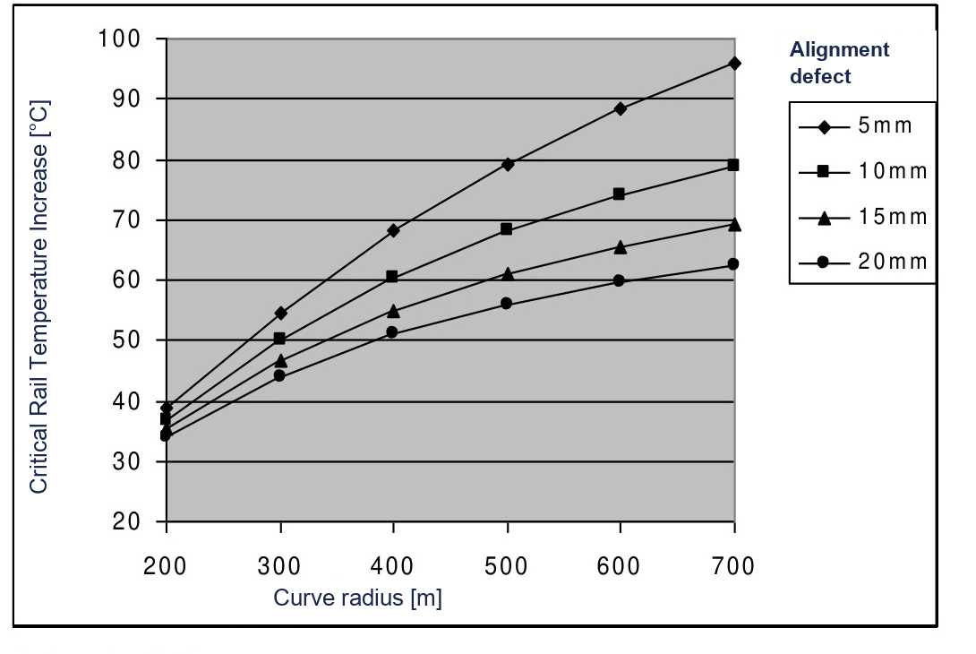
The lecture also presents the following separate example with a stress-free temperature of 19 °C. Its full resistance, inertia and correction-factor inputs are not stated, so these values cannot be reconstructed uniquely from the slide. They are retained as source examples of the effects of radius, sleeper type and maintenance, not as permissible work or operating temperatures. The following sensitivity calculation uses its own fully stated inputs.
| Sleeper type | Condition | \(R=250\) m [°C] | \(R=500\) m [°C] |
|---|---|---|---|
| Timber | Consolidated | 70 | 89 |
| Timber | After tamping | 53 | 68 |
| Timber | After ballast cleaning | 38 | 49 |
| Concrete | Consolidated | 97 | 120 |
| Concrete | After tamping | 72 | 91 |
| Concrete | After ballast cleaning | 49 | 64 |
Table 11.9 is a reproducible sensitivity example. Both assumed track systems use \(F=153.7\) cm\(^2\), effective \(J=1025.8\) cm\(^4\), \(E=2.10\times10^7\) N/cm\(^2\), \(\alpha=1.15\times10^{-5}\) K\(^{-1}\), \(f^*=2.0\) cm, \(k_1=k_2=1\) and \(T_{sf}=19\,^\circ\)C. System A starts with \(q_\mathrm{tot}=6\) kN/m; system B with \(12\) kN/m. The disturbed cases assume reductions of 50% and 70%, applied directly to \(w\) without a second consolidation factor. Use \(w=10q_\mathrm{tot}\) N/cm and \(R\) in cm in Eq. 11.10, then add \(T_{sf}\). These assumed systems do not define a sleeper material’s resistance or certify track safety.
| System and condition | Total LTR [kN/m] | Model temperature, \(R=250\) m [\(^\circ\)C] | Model temperature, \(R=500\) m [\(^\circ\)C] |
|---|---|---|---|
| A, initial | 6 | 53.1 | 70.9 |
| A, 50% reduction | 3 | 37.4 | 49.4 |
| A, 70% reduction | 1.8 | 30.4 | 39.0 |
| B, initial | 12 | 79.9 | 103.6 |
| B, 50% reduction | 6 | 53.1 | 70.9 |
| B, 70% reduction | 3.6 | 40.7 | 54.2 |
Actual work restrictions follow Bane NOR’s maintenance rules [6]. TRV:05016 differentiates tamping/lining temperature intervals by radius and whether lateral position can be checked. TRV:05017 normally limits other stability-reducing work to rail temperatures from 0 to +30 °C, subject to its stated exceptions. After tamping/lining in curves \(R<400\) m with the required ballast profile, TRV:05100 requires 40 km/h or less when rail temperature exceeds or is expected to exceed +30 °C, until 50,000 gross tonnes have passed. With a deficient ballast profile, TRV:05101 applies the restriction regardless of temperature. TRV:05102 provides the stated exception when a dynamic track stabiliser is used; the separate requirements for using that machine still apply. These selected examples do not reproduce the complete reopening rules: TRV:05098 also links speed to sleeper type, rail temperature and accumulated gross tonnage, and TRV:05099 limits non-neutralised track to at most 40 km/h. TRV:05096 extends the applicable reduction over the work section and 50 m beyond each end. Ordinary tamping at \(R=350\) m is limited to +10 to +30 °C; verified position references can lower the minimum to +5 °C. TRV:05016 separately excepts correction of existing buckling or faults beyond the immediate-action limit.
11.5.4 Diagnosing a Buckling Risk
The lecture groups the contributing mechanisms into increased loading and reduced resistance. Temperature, braking and interaction with bridges or turnouts can increase or redistribute rail force. Tight curvature and alignment defects increase the demand for lateral support. Weak components, an inadequate ballast profile and recent maintenance reduce the ability to resist that demand.
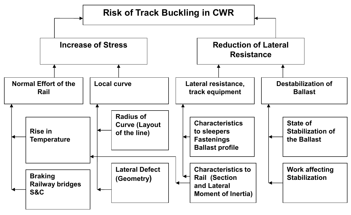
A practical review asks three connected questions:
- What changed the force? Establish rail temperature, the likely stress-free state, recent lining or welding, and nearby sources of longitudinal restraint.
- What reduced the resistance? Inspect ballast shoulders and cribs, maintenance history, fastening condition, sleepers and signs of poor drainage or fouling.
- Where can a defect grow? Examine alignment defects, tight curves, transitions and the possible effect of a passing train.
A photograph alone cannot establish the cause. The observations must be checked against measurements and maintenance records before selecting a remedy.
Use Figure 11.95 as a diagnostic exercise: describe the visible deformation, then identify the temperature, force, ballast and work-history evidence needed to test possible causes. The nearby vehicle is context, not proof of the initiating mechanism.
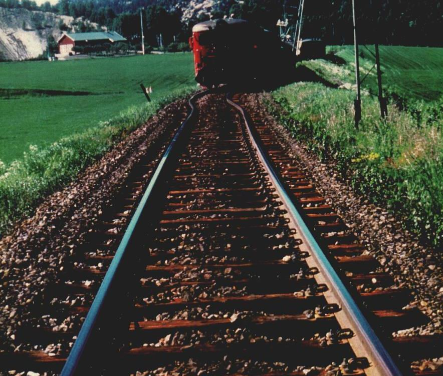
Follow the aligned rail ends in Figure 11.96(a), heating in 11.96(b) and finished joint in 11.96(c) as a construction sequence. Completion of the visible sequence does not replace the required weld inspection and acceptance.
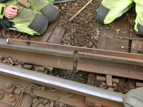
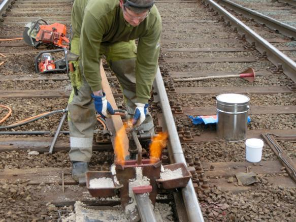
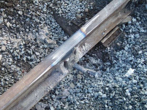
11.6 Chapter Summary
Thermal force. By removing most rail joints, CWR reduces impact loading, noise and maintenance at joints. The price is that thermal expansion and contraction are restrained over long lengths of rail, producing compressive force in hot weather and tensile force in cold weather. Neutral temperature is therefore one of the most important control parameters in CWR design and maintenance.
Longitudinal resistance. Fastenings, sleepers, ballast and connected structures resist rail creep and thermal movement. In the central track panel, movement is effectively restrained; in expansion zones, rail ends can move and rail gaps may change with temperature. Bridges, turnouts and maintenance activities complicate this behaviour because they introduce local changes in restraint and stiffness.
Buckling risk. High rail temperature creates compressive force, but buckling occurs only when the track does not have enough lateral resistance and alignment stability to resist that force. Small-radius curves, poor ballast shoulders, recent tamping, weak sleepers and geometry defects all reduce the buckling margin. This is why CWR safety is linked to rail temperature, track condition and maintenance history.
Destressing. Cutting, welding, tamping, ballast cleaning and other work can change the rail's locked-in stress state or reduce track resistance temporarily. Correct destressing restores the required neutral temperature range, while post-maintenance restrictions and inspections protect the track until resistance has recovered. Maintenance timing is therefore part of CWR safety management, especially in warm weather.
System thinking. Rail stress, fastening resistance, ballast condition, curve radius, bridges, turnouts, expansion devices and operational temperature range all interact. A CWR track with high-quality rail but poor lateral support is unsafe, while a well-supported track with incorrect neutral temperature can still be vulnerable. The engineering goal is to maintain a stable balance between thermal force and track resistance throughout the year.
Assignments
Use \(\alpha E=2.415\,\mathrm{N/(mm^2\,K)}\) for the force calculations unless a rounded value is explicitly requested. Where only a neutral temperature is given, assume that the actual stress-free temperature equals that target. Neglect residual end resistance in the simple breathing-length calculations.
Assignment 1: Rail thermal stress and neutral temperature
A 54E3 rail (\(A = 6948\,\mathrm{mm}^2\)) in a CWR section is laid at a stress-free temperature of \(18\,^\circ\mathrm{C}\) (at the lower limit of a \(21\pm3\,^\circ\mathrm{C}\) tolerance band). The rail temperature rises to \(52\,^\circ\mathrm{C}\) in summer and drops to \(-32\,^\circ\mathrm{C}\) in winter.
(a) Calculate the compressive force in one rail and in both rails at \(52\,^\circ\mathrm{C}\).
(b) Calculate the tensile force in one rail and in both rails at \(-32\,^\circ\)C.
(c) A rail neutralised exactly at the target (\(T_n = 21\,^\circ\)C) in the same temperature range would develop what maximum compressive and tensile forces in both rails?
(d) Which scenario is more critical for summer buckling, and which is more critical for winter fracture?
Assignment 2: CWR tamping in hot weather
A CWR section in a curve of \(R = 350\) m with concrete sleepers is being tamped in midsummer with a rail temperature of \(42\,^\circ\mathrm{C}\). The neutral temperature is \(21\,^\circ\mathrm{C}\). The pre-tamping total LTR for the track panel is 12 kN/m; after tamping, it drops to 40 %. The total compressive force in both rails is 800 kN.
(a) What is the required total LTR per metre using \(q_\mathrm{tot}=P_\mathrm{tot}/R\)?
(b) Does the post-tamping LTR satisfy this requirement?
(c) May ordinary tamping continue at this rail temperature under TRV:05016? Distinguish the normal work-temperature limit from the simple radial-equilibrium check and from the stated exceptions for urgent defect correction.
(d) What operational measures should be taken immediately?
Assignment 3: CWR destressing calculation
A CWR section is to be destressed in spring. The rail temperature at the time of destressing is \(12\,^\circ\mathrm{C}\), but the target neutral temperature is \(21\,^\circ\mathrm{C}\).
(a) Explain the procedure for achieving the correct neutral temperature by releasing the rail stress and using controlled heating or mechanical stretching, with allowance for closure welding.
(b) If the track is destressed and fastened without heating or controlled mechanical stretching, what will the actual stress-free temperature \(T_{sf}\) be, and what is the consequence for summer compressive forces?
(c) Bane NOR allows \(T_n = 21 \pm 3\,^\circ\mathrm{C}\) [11]. Assume the rail has been fully stress-released and its actual stress-free temperature is documented as \(18\,^\circ\mathrm{C}\). Does that state comply with the temperature tolerance, and why can it still be less favourable for summer buckling than \(21\,^\circ\mathrm{C}\)? Explain why laying temperature alone does not establish compliance (TRV:05377–05378).
Assignment 4: CWR breathing length
The breathing length of a CWR section is the zone near a free rail end where longitudinal displacements occur with temperature changes. For one 54E1 rail (\(A = 6\,934\,\mathrm{mm}^2\), \(E = 210\,\mathrm{GPa}\), \(\alpha = 1.15\times10^{-5}\,\mathrm{K}^{-1}\)) on concrete sleepers with a ballast longitudinal restraint of \(r_\ell = 10\,\mathrm{kN\,m^{-1}}\) per rail:
(a) Derive an expression for the breathing length \(L_e\) in terms of the temperature change \(\Delta T\).
(b) Calculate \(L_e\) for \(\Delta T = 40\,\mathrm{K}\).
(c) For an idealised force-transfer check, assume that an 80 m anchorage length has a fully mobilised, constant longitudinal resistance of \(10\,\mathrm{kN/m}\) per rail. A bridge adds \(120\,\mathrm{kN}\) per rail in the same direction as the thermal force in part (b). Does \(r_\ell L\) exceed the combined force? Explain why this equilibrium check does not establish the adequacy of a real rail–bridge system, and why an ordinary weld is not a free rail end.
Assignment 5: CWR buckling check
A CWR track section on a curve of \(R = 400\,\mathrm{m}\) has a rail temperature \(22\,^\circ\mathrm{C}\) above the neutral temperature \(T_n\). The lateral ballast resistance after recent tamping is \(q_\mathrm{rail} = 8\,\mathrm{kN\,m^{-1}}\) per rail. Use the legacy UIC60 dataset (\(A = 7686\,\mathrm{mm}^2\); use the lateral rail inertia \(I_\mathrm{lat} = 512.9\,\mathrm{cm}^4\) per rail for the Meier calculation, not the vertical bending inertia).
(a) Calculate the total axial compressive force \(P_\mathrm{tot}\) in both rails.
(b) Calculate the required total lateral track resistance per metre \(q_{\mathrm{tot,req}}=P_\mathrm{tot}/R\).
(c) Convert the available resistance to the same whole-track convention (\(q_\mathrm{tot}=2q_\mathrm{rail}\)). Does the post-tamping resistance satisfy the simple radial-equilibrium requirement?
(d) Using the Meier–Chatkeo method for curved track (Eq. 11.10) with the supplied model amplitude \(f^* = 1.5\,\mathrm{cm}\), \(J = 2 \times 512.9\,\mathrm{cm}^4\), \(F = 2 \times 76.86\,\mathrm{cm}^2\), \(R = 40{,}000\,\mathrm{cm}\), \(k_1 = k_2 = 1\), and \(w = 2q_\mathrm{rail}=160\,\mathrm{N\,cm^{-1}}\), estimate the critical temperature increase \(\Delta t_\mathrm{cr}\). Compare the actual increase (22 \(^\circ\)C) with the model estimate. Why does this comparison alone not establish a safe operating temperature?
Assignment 6: Longitudinal resistance and rail-gap behaviour
A ballasted track with continuously welded rail of rail type 60E1 has an average longitudinal ballast resistance \(r_\ell = 8\) kN/m per rail. During one hot summer, the rail temperature was measured to be 56 \(^\circ\)C. The neutral temperature of the rail is 21 \(^\circ\)C (Bane NOR technical regulations). Use the following parameters:
-
Cross-sectional area of two 60E1 rails: \(F = 2 \times 76.9\,\mathrm{cm}^2 = 153.8\,\mathrm{cm}^2\)
-
Modulus of elasticity: \(E = 210 \times 10^5\,\mathrm{N\,cm^{-2}}\)
-
Coefficient of thermal expansion: \(\alpha = 1.15 \times 10^{-5}\,\mathrm{K}^{-1}\)
The longitudinal ballast resistance is used only for the breathing-length calculation in part (c); part (b) asks for the required lateral resistance and should not be checked against \(r_\ell\).
(a) Calculate the total axial compressive force \(P_\mathrm{tot}\) in both rails at \(T = 56\,^\circ\)C.
(b) Calculate the total lateral resistance per unit length required for radial equilibrium in a curve of \(R = 500\) m.
(c) At what distance from the free end of the CWR section does one rail reach the locked-zone axial force? (Breathing length for \(\Delta t = 35\,^\circ\)C using \(r_\ell = 8\) kN/m per rail.)
Assignment 7: Interpreting a buckling incident
Use the Hønefoss photograph in Figure 11.30 together with the influence diagram in Figure 11.94.
(a) List what can be observed directly in the photograph. Keep observations separate from assumptions about the cause.
(b) Suggest one mechanism that could increase or redistribute rail force and two mechanisms that could reduce lateral resistance.
(c) Which temperature, alignment, maintenance and component records would you request before deciding which mechanism was responsible?
(d) Explain why restoring the visible alignment alone may not resolve the underlying problem.