Switches and Crossings
In this chapter
Switches and crossings let trains change tracks, reach platforms and pass through junctions. This chapter follows the lecture in three connected parts: components and operation, geometry and layouts, and loading and maintenance.
16.1 Components and operation
16.1.1 Turnout anatomy
Technical requirements were checked against Bane NOR on 4 November 2026. Design, signalling and maintenance requirements apply at their specified locations; the simplified calculations below explain the governing relationships.
A simple turnout can be divided into a switch panel, closure panel and crossing panel. This subdivision, shown in Figure 16.1, is useful because each panel creates a different wheel-guidance problem.
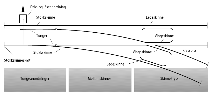
The original drawing uses Norwegian labels: stokkskinne (stock rail), tunger (switch blades), driv- og låseanordning (drive and locking device), vingeskinne (wing rail), krysspiss (crossing nose), and ledeskinne (check rail). Its three shaded zones are the switch panel, closure rails and crossing panel, read from left to right.
The three panels form one route. The switch panel selects it, the closure rails connect it, and the crossing panel carries the wheels through the intersection. Movement, support and guidance must therefore be understood together.
A simple turnout can be read as the three functional panels introduced in Figure 16.1, with each panel carrying a different part of the wheel-guidance task:
-
Switch panel: Contains fixed stock rails and movable switch blades or tongues, which move laterally against the stock rails. The switch panel determines whether a train is routed to the straight track or the diverging track.
-
Closure panel: The transition between the switch panel and the crossing panel. Contains closure rails that guide the wheel from the switch blade to the crossing.
-
Crossing panel: Contains the crossing or frog/heart piece, wing rails, and check rails. The crossing allows one rail to cross the other.
16.1.2 Switch panel
The stock rails remain fixed. The switch blades, or tongues, move laterally against them to guide the wheel to either track. The toe is the thin entry end of a blade; the heel is its connection towards the closure rail. Toe machining establishes contact with the stock rail, whereas the heel arrangement and flexible region determine how the blade moves. Tongues are characterised by their flexibility and movement principle:
Rigid blades: heel joint
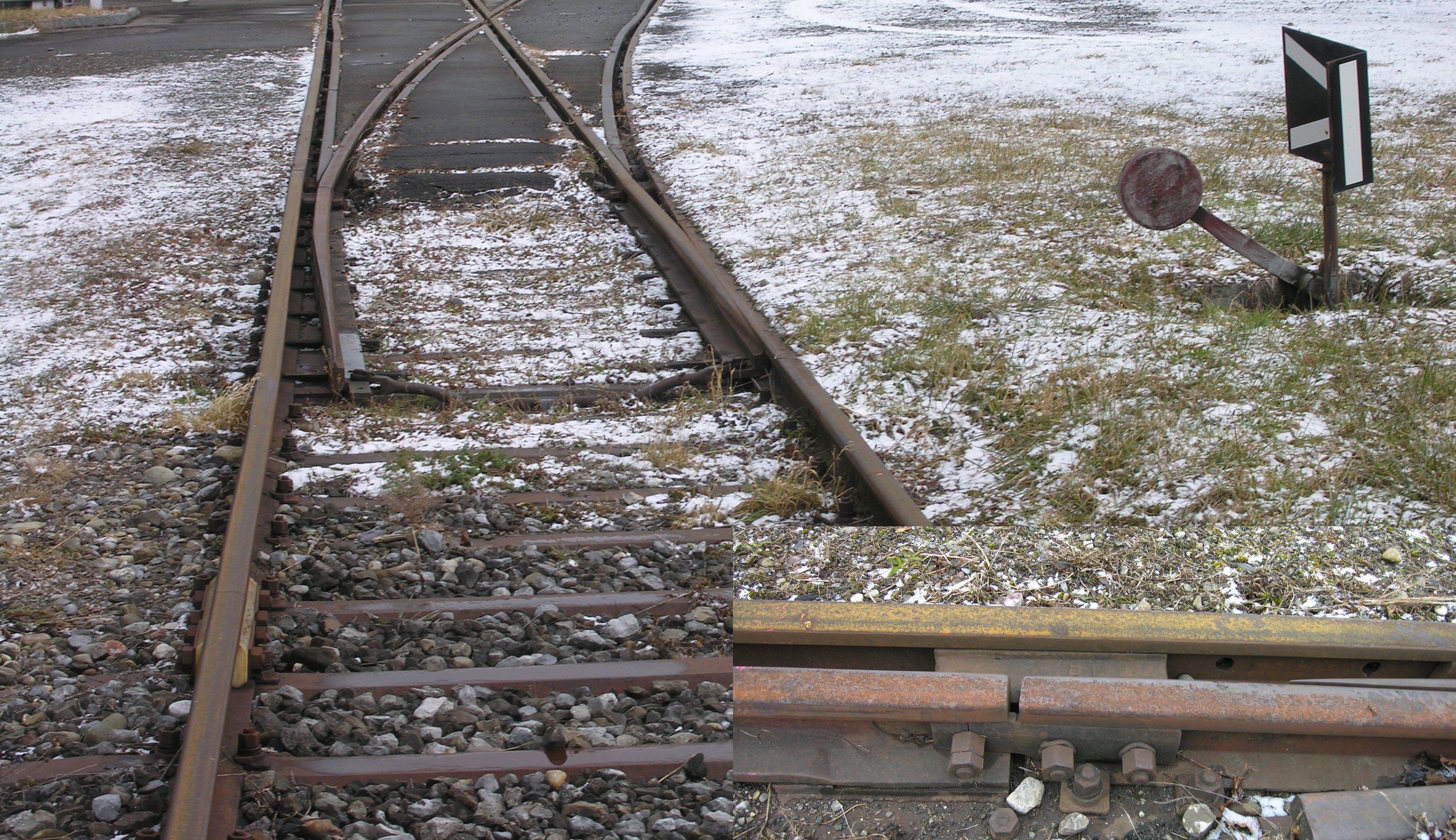
In rigid point switches, the tongue is a separate rail element that pivots at a mechanical joint at its heel, where it connects to the closure rail. The stock rail remains beside the blade. The joint introduces wear and a local stiffness discontinuity, making the arrangement less favourable for long, high-speed tongues. Figure 16.2 shows the complete jointed arrangement and an inset of the fishplated heel joint. The joint permits blade rotation; it should not be mistaken for a separate hinge pin.

Flexible blades: elastic movement
Flexible switches achieve lateral movement by elastic bending over a designed length rather than rotation about a mechanical heel hinge. Blade profile, length and support determine the flexibility. Longer blades can provide a gentler entry geometry, but permitted speed depends on the complete turnout and its operating equipment. Flexible describes the movement principle; it does not mean that every flexible blade has the same welded construction.
Flexible blades: welded arrangement
One common continuous arrangement is the welded flexible switch:
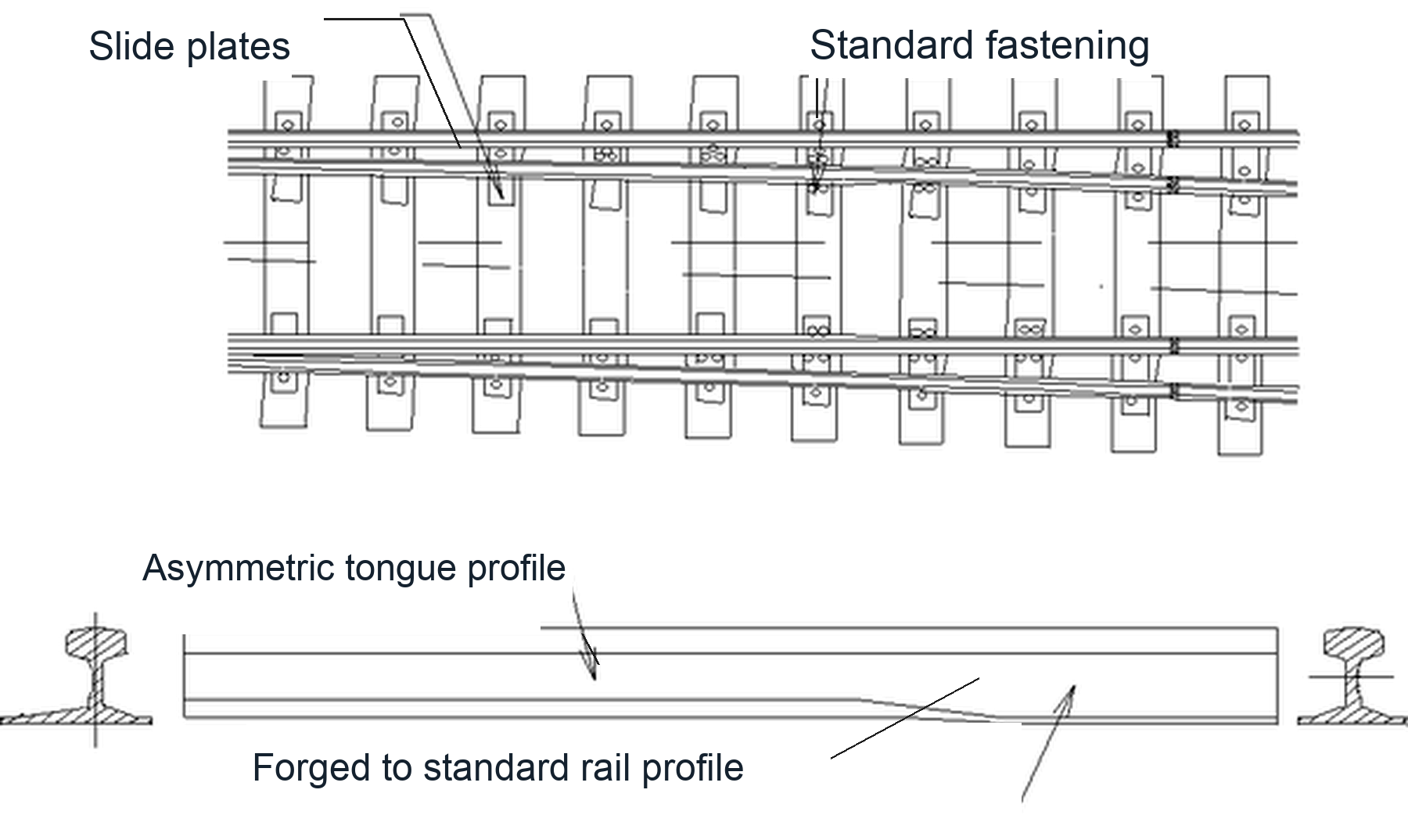
Welded flexible switches: One construction joins the special blade section to the adjoining rail by welding. The profile transition and elastic bending region are design-specific. The weld removes a mechanical joint at that connection; it does not remove all impact, bending stress or maintenance. Other flexible designs use a continuous asymmetric blade profile with a forged transition towards the standard rail section.
Figure 16.3 shows a flexible blade with an asymmetric profile and a transition towards a standard rail section. The machined toe permits progressive wheel-load transfer, while elastic bending accommodates lateral movement. The drawing should not be read as proof that every flexible blade contains a weld.
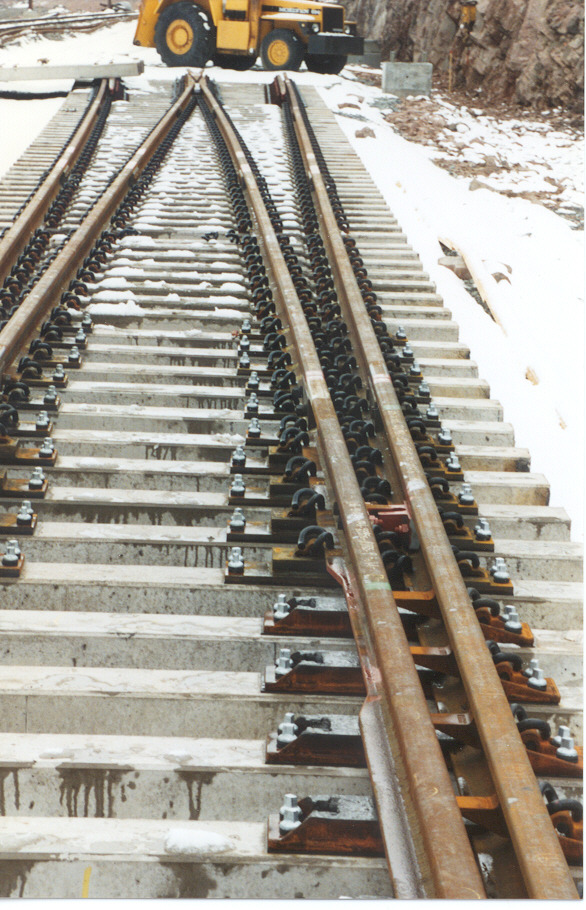
The field view in Figure 16.4 shows an installed blade beside its stock rail. It illustrates the contact region and supporting components; the photograph alone does not establish the detailed heel or weld construction.
The tip of the tongue is machined to a sharp point (the toe) so that it can lie closely against the stock rail when in the closed position. Wheel loads at the tip are transmitted to the stock rail; as the wheel progresses toward the heel, the load is progressively transferred to the tongue.
Slide plates
The tongue rests on slide baseplates that allow it to slide laterally with low friction when the switch is operated. The baseplates must:
-
Provide a stable, smooth bearing surface for the tongue movement
-
Transmit the vertical load from the tongue to the sleeper
-
Resist wear from the repeated sliding motion
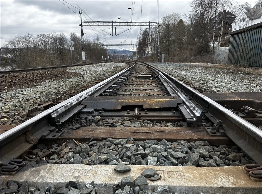
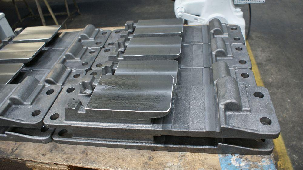
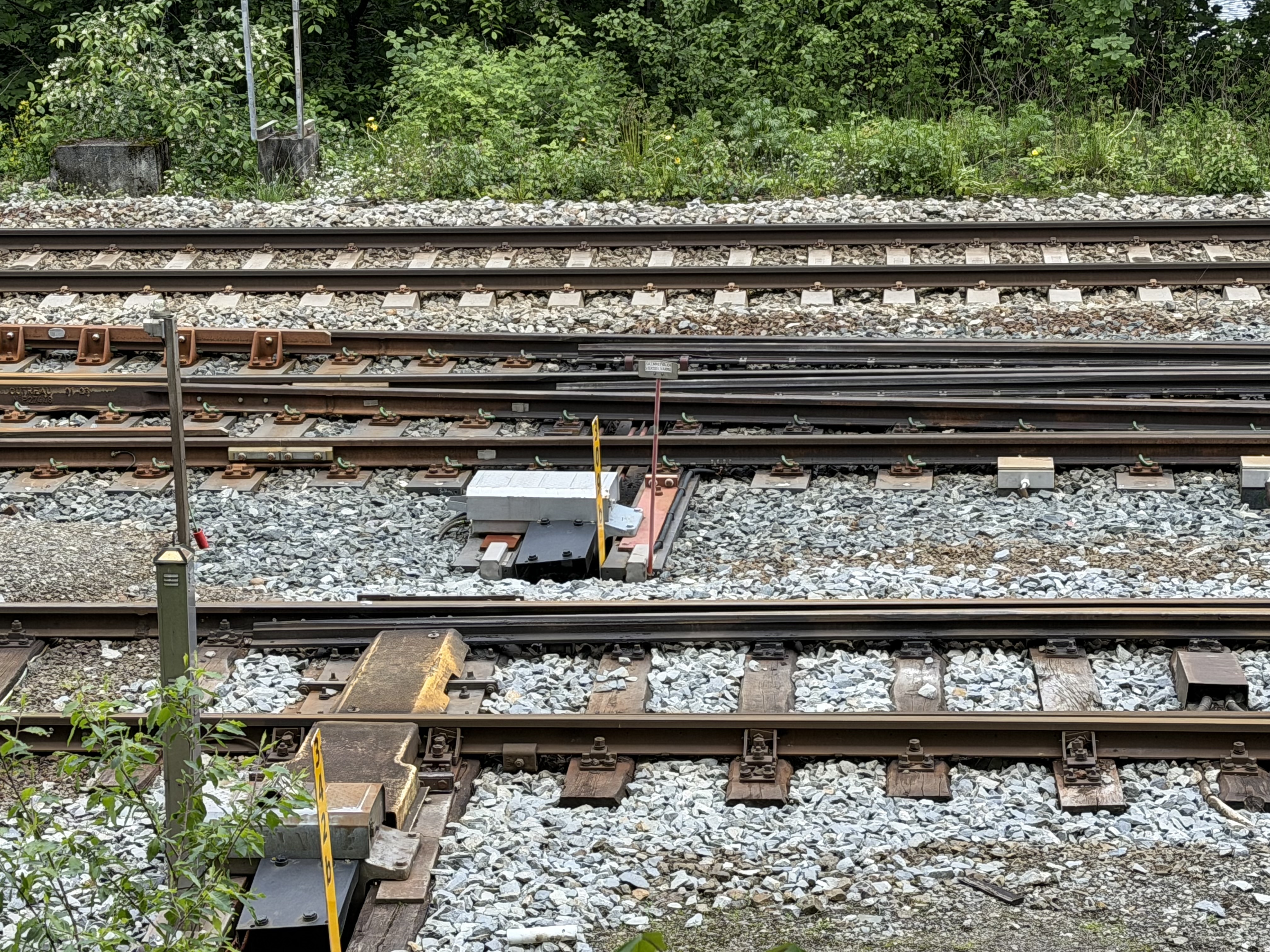
The slide baseplates, bearing details and drive hardware in Figure 16.5 carry the tongue while letting it move. The middle photograph shows manufactured slide chairs with the blades absent, making the raised bearing surfaces visible. Surface care is product-specific: lubricated and grease-free coated chairs require different maintenance treatments. Wear, contamination or poor support can increase movement resistance and prevent complete closure.
The blade-support photograph in Figure 16.5(a) shows the installed assembly. The exposed slide chairs in 16.5(b) make their supporting surfaces easier to see; 16.5(c) locates the operating hardware.
Blade load transfer
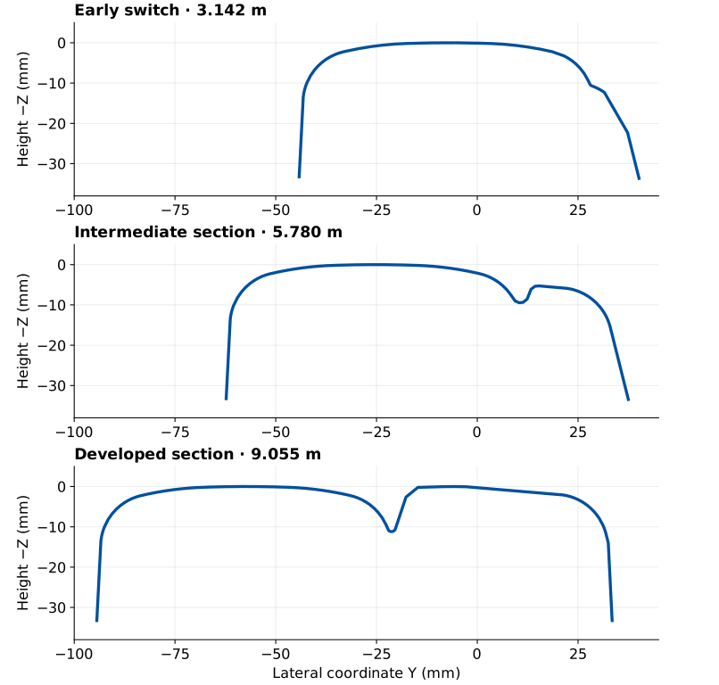
Figure 16.6 shows how the running-surface profile changes along a real turnout dataset. Read the three sections at the same scale: the available rail-head shape changes as the wheel travels from the blade toe towards the closure rails. These are measured combined surface contours, not separate solid drawings of a stock rail and blade. Contact force cannot be inferred from the contours alone.
16.1.3 Point operation
The point operating apparatus moves the switch blades between their two end positions (normal and reverse) and locks them in position. For a centrally controlled turnout, it provides proof of both locking and the required blade or movable-nose positions to the interlocking. Locking proof and position proof are independent functions; a completed motor stroke is insufficient. Modern enclosed point machines combine the actuator, transmission, locking and position-detection interfaces in a compact unit; Bane NOR's ERTMS asset register lists ELS710 point machines, and current switch-and-crossing specifications reference Siemens ITS 710 interfaces for switch blades and swing-nose crossings [54, 52]. Figure 16.7 shows the installation principle: the enclosed actuator is mounted beside the switch and drives the blades through external rods.
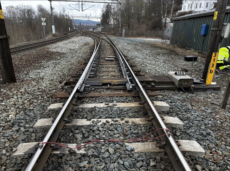
Linkage geometry comprises the rod lengths, angles and attachment positions that convert machine travel into blade movement. Firm, aligned mounting allows the linkage to complete its travel without binding. The external photograph does not establish the internal detector arrangement or machine model.
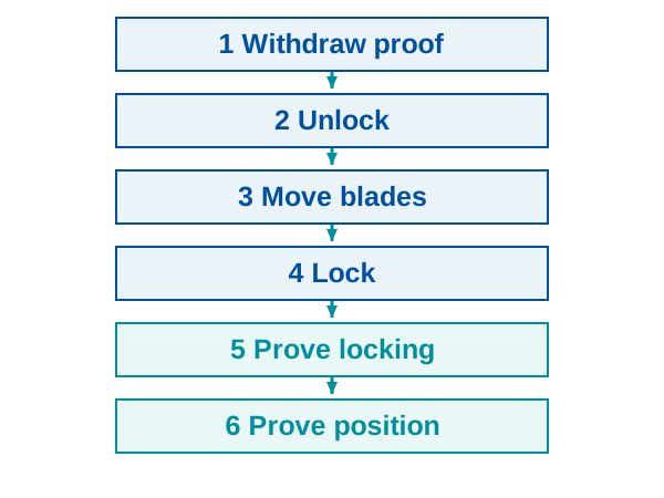
The prescribed operating sequence is: withdraw proof, unlock, move, lock, prove locking, then prove position (TRV:05556). Locking and position checks must be independent (TRV:05572; TRV:05577). Turnout proof is one route condition; applicable clear-track, conflicting-route and protection conditions must also be satisfied before normal movement authority is issued.
Locking and route proving
- Withdraw proof. The previous proved state is removed before any movement starts. The turnout cannot be treated as ready for a new train movement during the change.
- Unlock. Release the mechanism that holds the blades in their current position.
- Move. The drive and rods move both blades towards the commanded position. One blade closes against its stock rail while the other opens to provide flange clearance.
- Lock. Secure the blades in the selected position. A completed motor stroke alone does not establish that the blades are locked.
- Prove locking. Check that the locking mechanism has actually engaged.
- Prove position. Independently check the required blade positions and, where fitted, the movable crossing position. The indication must correspond to the commanded route.
Figure 16.8 follows the same six stages from the command to the final independent checks. Read the arrows in order; failure to obtain either proof prevents completion.
Normal movement authority
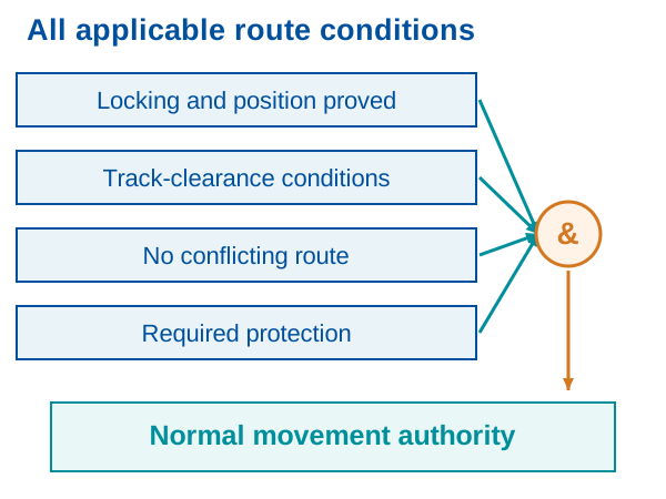
The interlocking combines these turnout indications with the other conditions for the complete route. It checks the required track-clear indications, prevents conflicting routes, and verifies the applicable protection arrangements before it issues normal movement authority. Correct turnout indication is necessary, but it is only one part of this decision.
Key requirements for point machines:
-
Required movement and open-blade clearance depend on turnout type and drive configuration; a generic actuator stroke is not a safety acceptance criterion.
-
Locking must retain the selected position under specified loads. A trailing run-through can damage a non-trailable mechanism and must not be described as a normal operating condition.
-
The installed detection arrangement must prove the required blade and crossing positions and locking before the interlocking authorises the route; the number of drive and detection points is turnout-specific.
-
Switch heaters protect the tongue–stock-rail area against snow and ice so the tongue can close and be detected correctly.
Figure 16.9 places the turnout checks within the whole route. The AND junction means that every applicable condition must be met.
Blade closure and clearance
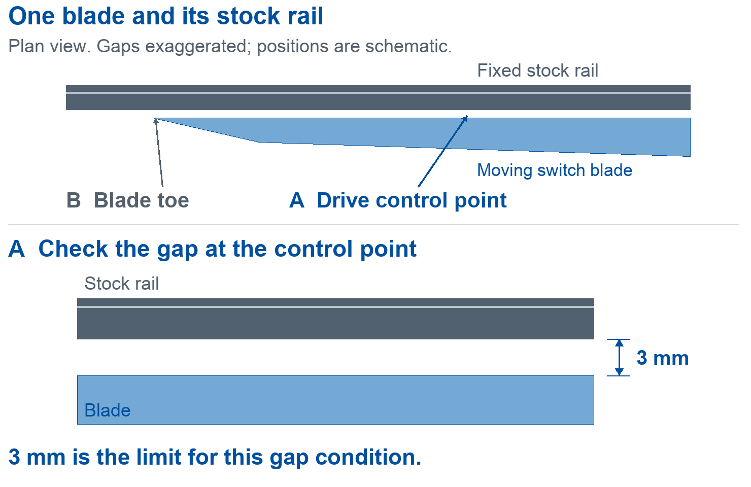
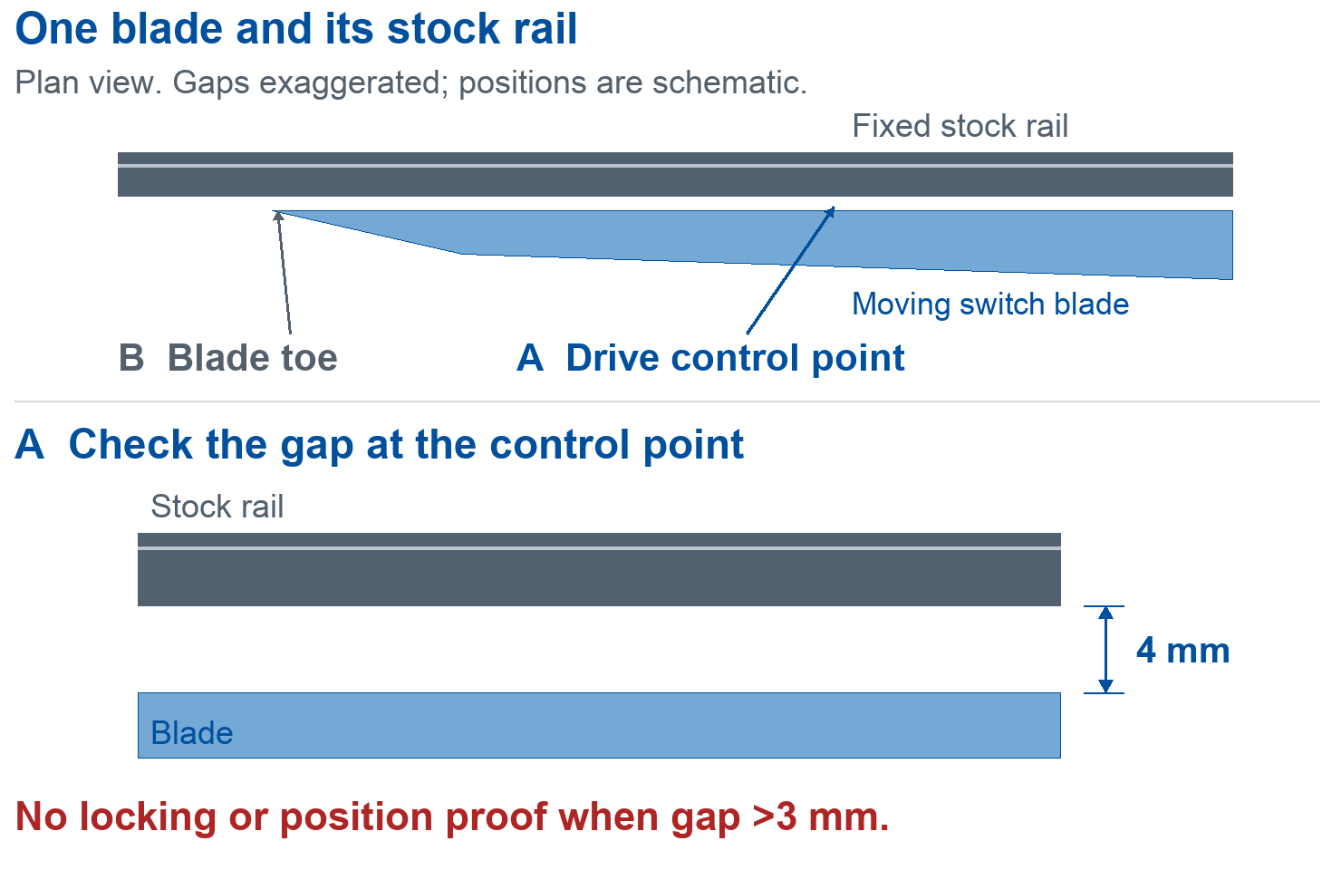
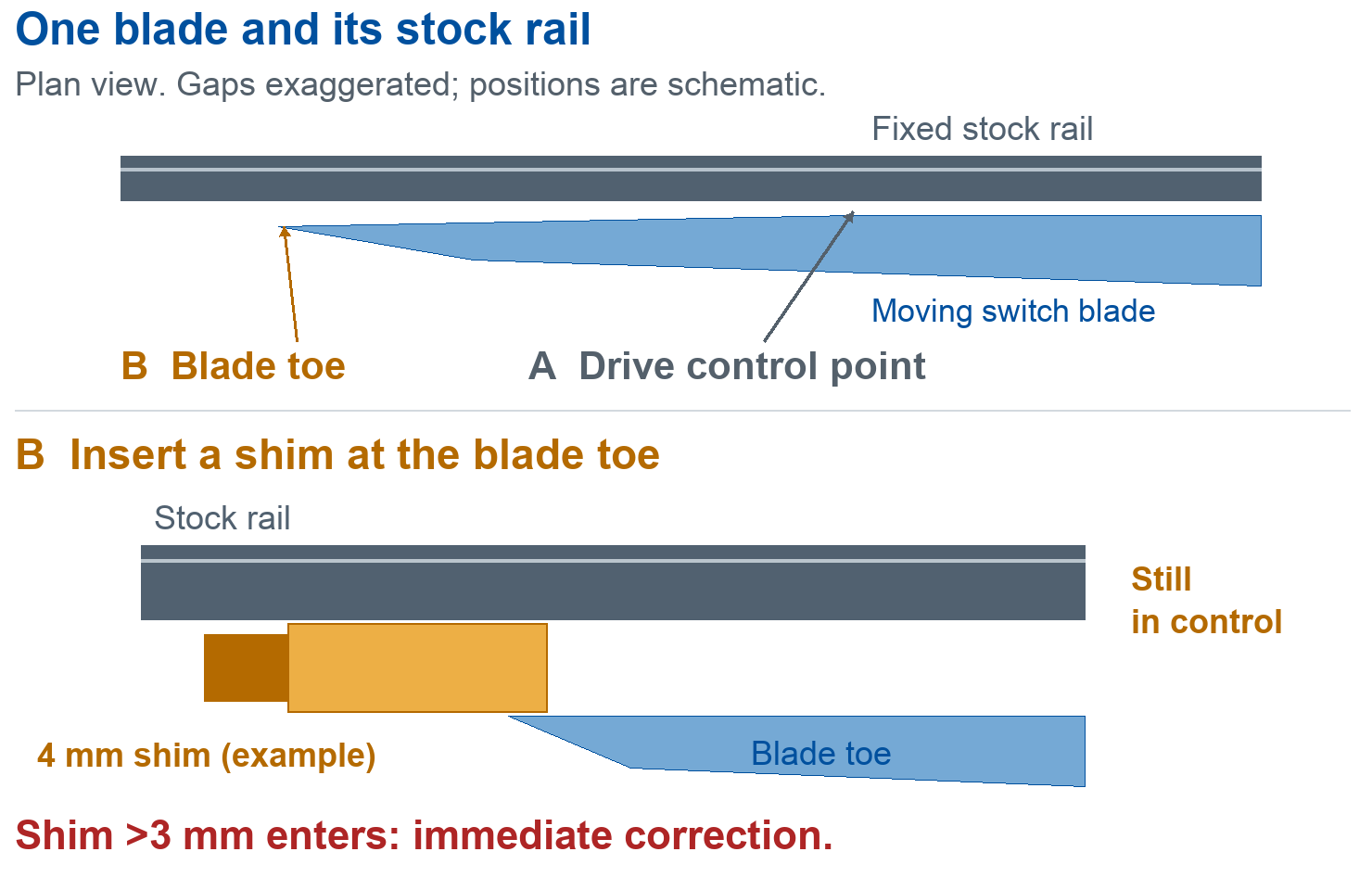
Design proof of locking and position is permitted only with a closed blade/nose gap no greater than 3 mm at the drive control point (TRV:05544). Maintenance separately requires immediate correction if a shim thicker than 3 mm fits at the tongue tip while the turnout is detected (TRV:04419). These are different measurement locations. Open-tongue tip minima are 160 mm with one drive and 110 mm with two or more (TRV:04423); free flange passage is normally at least 58 mm along the entire tongue, with specified single-drive 1:9 exceptions of 49 mm for R300 and 55 mm for R190 (TRV:04422).
Figure 16.10(a) marks the design control point and its 3 mm limit. In 16.10(b), an excessive gap must prevent proof. In 16.10(c), a shim thicker than 3 mm fits at the blade toe while detection remains proved, requiring immediate correction. The illustrated 4 mm shim is one example; the gaps are exaggerated and the drawing does not replace the prescribed test procedure.
16.1.4 Crossing panel
The crossing panel combines wheel support and lateral guidance where the rail paths intersect. At a fixed crossing, the running edge is interrupted to provide flange passage; the wing rails, crossing nose and opposite check rail work together to guide the wheelset.
Crossing geometry
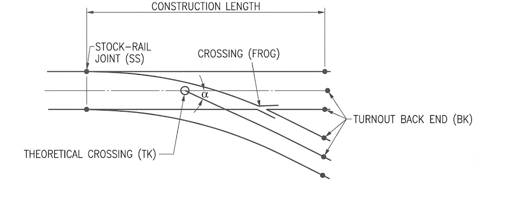
The crossing (frog or heart piece) is where the rail paths intersect. The designation \(1:N\) describes the overall turnout angle \(\alpha\), between the main-track centreline tangent and the tangent to the diverging centreline at its curve end. Their intersection is the theoretical crossing (TK), separate from the physical crossing nose. The number \(N\), often called the crossing number in turnout descriptions, is the corresponding length-to-opening ratio. In a long-curve turnout the local crossing angle can differ from \(\alpha\) and must be read from the actual drawing (Bane NOR, Sporvekslers geometri).
Figure 16.11 distinguishes TK, the intersection of the route-centreline tangents, from the physical crossing nose. The angle between those tangents defines the turnout designation.
Common Norwegian crossing numbers include \(N = 7\), 9, 12, 14, 15, 18.4, and 26.1 [80, 48]. A higher crossing number indicates a smaller, flatter turnout angle and usually a larger-radius, longer turnout; crossing number alone does not authorise a speed. For example:
-
N = 7, \(\alpha \approx 8.1^\circ\): 1:7 R190, normally 35 km/h (40 km/h only under the stated non-passenger exception)
-
N = 12, \(\alpha \approx 4.8^\circ\): 1:12 R500, normally 60 km/h without cant
-
N = 18.4, \(\alpha \approx 3.1^\circ\): high-speed turnout, \(v_{\mathrm{div}} \leq 100\) km/h
-
N = 26.1, \(\alpha \approx 2.2^\circ\): high-speed turnout, \(v_{\mathrm{div}} \leq 140\) km/h
For a designation \(1:9\) R300, \(N=9\) gives \(\alpha=\arctan(1/9)\approx6.34^\circ\), while R300 separately identifies the 300 m radius. The angle calculation does not establish a permitted speed.
Wheel contact transfer
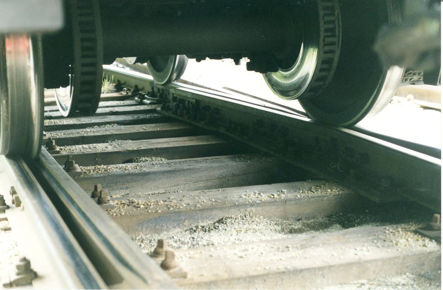
The flangeway at a fixed crossing accommodates a wheel flange travelling on the intersecting route. During wheel passage, wheel contact and load shift between the wing rail and crossing nose. Effective support depends on tread profile, crossing geometry and wear; a correctly shaped crossing can provide overlapping support. Figure 16.12 shows flange passage, not a universally unsupported tread length. Any loss of support must be established from the actual wheel–rail contact geometry.
Changes in contact trajectory, profile or support can produce high dynamic forces and contribute to cracking, spalling or plastic deformation at the nose [148]. Peak forces depend on speed, wheel and crossing condition, and the coupled vehicle–track response. A photograph or crossing label does not establish a fixed amplification factor; site-specific values require measurement or a validated dynamic model.
Construction and materials
Fixed crossings are built either as machined rail assemblies or as one-piece castings. The schematic and field photo in Figure 16.13 show the same idea at two levels: the running-edge geometry and the cast crossing installed in track.
Compare the running-edge arrangement in Figure 16.13(a) with the installed cast component in 16.13(b). The first explains the wheel path; the second shows how the crossing is constructed.
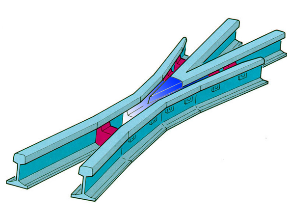
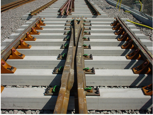
Crossing construction and material should be distinguished. A fixed crossing may be built from rail sections or use a cast crossing body. Austenitic manganese steel work-hardens under repeated loading; other designs use rail or forged components. Material selection, weldability and repair procedures follow the approved product specification. These categories do not replace the separate distinction between fixed and movable running-edge geometry [52].
Movable crossings
A movable crossing uses either a movable nose or a movable wing rail, set for the selected route, to close that route's running-edge gap. This removes the corresponding gap-related contact mechanism and can reduce dynamic loading and wear. Profile mismatch, changes in stiffness and inadequate support can still generate dynamic forces. The movable-nose arrangement in Figure 16.14 is one way to provide the continuous running edge.
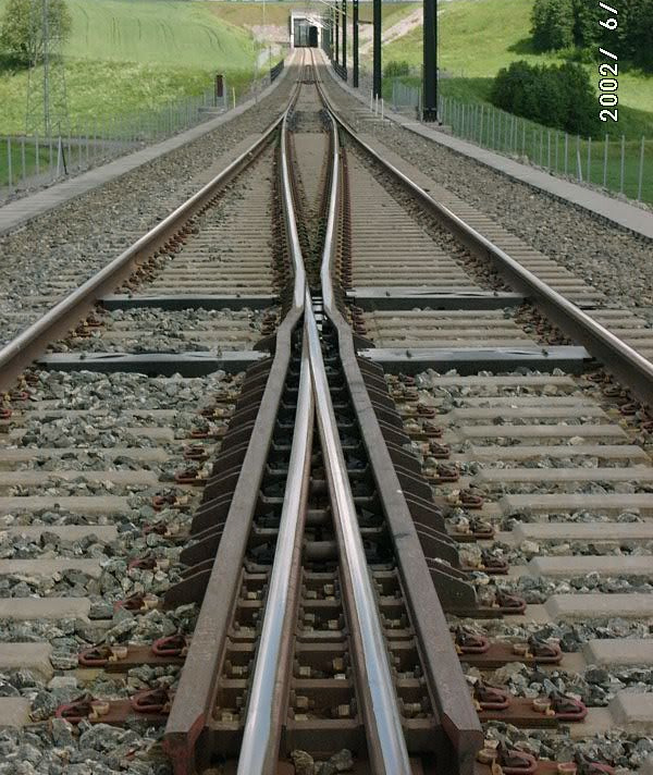
Movable crossings require additional point machines for the nose movement and detection, but the improvement in dynamic performance and reduction in maintenance can offset the additional complexity. Under current Bane NOR technical regulations, turnouts with a base radius of 1200 m or larger shall have a movable crossing, and movable crossings shall also be used for turnout speeds above 250 km/h. They are recommended for noise-sensitive areas, axle loads above 22.5 t, high traffic loading above 10 MGT/year, and turnout speeds above 130 km/h [48].
Wing rails and check rails
Because the running edge is interrupted at the nose, the wheelset must be positively guided through the crossing. The check rail visible in Figure 16.15 controls the back of the opposite wheel flange. In the complete crossing panel, it works together with the wing rails near the nose to guide the wheelset safely through the gap.
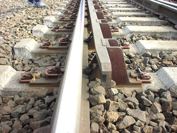
The complete crossing-panel layout in Figure 16.16 places these components together: wing rails leading up to the crossing nose and a check rail on the opposite rail.
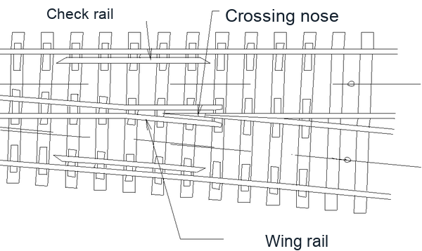
Wing rails guide the wheel from the closure rail towards the nose of the crossing. They are bent outward from the crossing nose to form a smooth path.
Check rails are short rail sections installed on the opposite rail from the crossing. They constrain the lateral position of the wheel flange so that the wheel tread passes over the nose of the crossing instead of entering the gap. The check gauge and flangeway dimensions must be maintained at their specified measuring sections; they must not be confused with the opening between an open tongue and its stock rail.
16.1.5 Maintenance intensive
The component functions explain why a turnout requires more maintenance than plain track. Blades and locking equipment must move reliably; contact transfers between different rails; and long sleepers support several connected routes. Wear, contamination or loss of support can therefore affect both wheel guidance and the ability to set a route.
Maintenance effort depends on traffic, layout and condition. The detailed inspections and interventions are introduced in the final part, after the geometry and force mechanisms are understood.
16.2 Geometry and layouts
Switch geometry connects the movable tongue rail, closure rails, and crossing into one continuous route. The key dimensions determine both the permissible speed and the space needed in a station layout.
16.2.1 Reference points and dimensions
The geometry of a simple turnout is determined by reference points and lengths such as the stock-rail joint, theoretical intersection, end of curve, back end of switch, construction length, tangent-length components, turnout radius and crossing angle. Figure 16.17 shows the standard notation for the main dimensions before the speed relation is introduced.
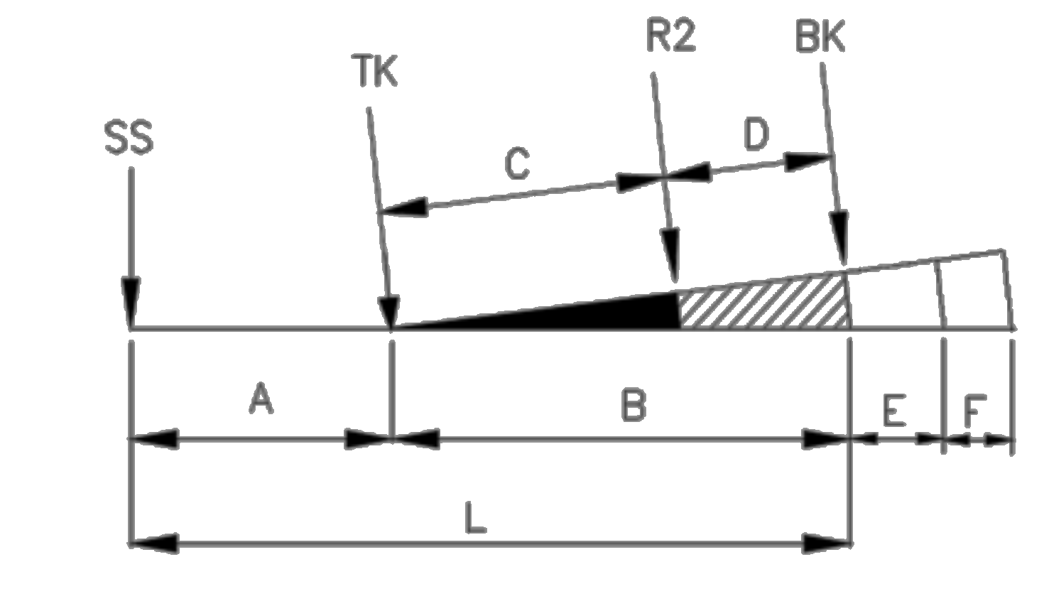
The drawing retains the Norwegian reference abbreviations: SS (stokkskinneskjøt, stock-rail joint), TK (teoretisk kryss, intersection of the route-centreline tangents), R2 (the labelled end of the circular curve), and BK (bakkant sporveksel, turnout back end). R2 is a point label, not a second numerical radius. TK is a geometric reference, separate from the physical crossing nose.
Turnout radius \(R_w\): The radius of curvature of the branching track through the switch zone. The diverging speed limit through the turnout is primarily determined by this radius and the applied cant (superelevation).
Turnout angle and designation \(N\): The Bane NOR designation \(1:N\) defines the angle between the main-track centreline and the tangent to the diverging centreline at the curve end, as described above. It does not by itself specify the radius or the local angle at a curved rail crossing.
Construction length \(L\): The distance from the stock-rail joint (SS) to the turnout back end (BK), with \(L=A+B\) in Figure 16.17. The long- and short-sleeper zones \(E\) and \(F\) extend beyond BK and add to the installed footprint. A lead length measured from the tongue toe to the theoretical rail-crossing point is a different dimension; the rail-crossing point must not be confused with TK, which is the intersection of the track-centreline tangents.
16.2.2 Allowable speed
A radius-based speed estimate for the diverging route follows from the turnout radius, the cant applied (typically zero on standard turnouts), and the selected cant-deficiency limit. It gives the allowable speed from the stated cant-deficiency limit. The operating speed must also satisfy the turnout-specific limits below:
where \(v_{\mathrm{allow}}\) is in km/h, \(R_w\) is in metres, and \(h_a\), \(I_{\max}\), and \(S\) are entered in the same length unit. The effective rolling-contact spacing is normally taken as \(S = 1500\) mm; \(h_a\) is the applied superelevation, typically 0 for standard turnouts; and \(I_{\max}\) is the maximum permitted cant deficiency [48].
For the shorter turnout types, the permitted speeds in the technical regulations are lower than this cant-deficiency formula alone would suggest. The abrupt change of curvature at the switch toe (entry jerk) and the tongue geometry also limit the permissible diverging speed, so the tabulated values in Table 16.1 include these effects.
| Turnout type | Div. speed [km/h] | Comment |
|---|---|---|
| 1:7 R190 | 35 | Up to 40 km/h only in yards or tracks without passenger traffic |
| 1:9 R190 | 35 | Same non-passenger 40 km/h exception as 1:7 R190 |
| 1:9 R300 | 40 | 50 km/h only after local technical and operational assessment |
| 1:12 R500 | 60 | Standard station/main-line turnout |
| 1:14 R760 | 80 | Higher-speed diverging route |
| 1:15 R760 | 80 | Alternative geometry with same basic radius |
| 1:18.4 R1200 | 100 | Clothoid turnout with movable crossing |
| 1:26.1 R2500 | 140 | Clothoid turnout with movable crossing |
For new passenger routes, the diverging radius must be at least 300 m (TRV:02696); existing smaller-radius turnouts are a separate case. Do not infer straight-route permission from the line speed alone: hinged tongues and diamond/slip crossings have a 100 km/h ceiling, and a 1:8 slip has a 70 km/h ceiling (TRV:02713, TRV:02714, TRV:02715). Locking and securing can impose lower limits (TRV:02716, TRV:02717).
Example: R300 allowable speed
For \(R_w=300\) m, \(h_a=0\), \(I_{\max}=100\) mm and \(S=1500\) mm, first use consistent length units:
This is the allowable speed from the supplied cant-deficiency limit. For a standard 1:9 R300 turnout, the ordinary turnout limit is 40 km/h; the 50 km/h exception requires the stated local technical and operational assessment. The lower governing limit controls normal operation.
16.2.3 Clothoid turnouts
The standard Norwegian high-speed forms 1:18.4 R1200 and 1:26.1 R2500 use clothoid geometry. Clothoids are therefore used in selected turnout designs, rather than in every turnout.
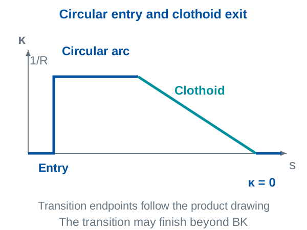
A clothoid turnout contains a transition curve as one of its geometric elements. Curvature changes progressively along the transition, spreading the change in lateral acceleration over a finite length. Its position must be read from the product drawing: a clothoid does not necessarily begin at the tongue tip.
The Norwegian forms described in Bane NOR's Sporvekslers geometri, Section 5.2 begin with a circular diverging arc followed by a clothoid towards the exit. Curvature therefore decreases towards zero along that transition, which can continue beyond the turnout back end. The initial change from the tangent into the circular arc remains; these forms must not be described as having a smooth entry transition at the toe. The general transition-curve principle is covered in Chapter 7. Bane NOR prohibits curving a clothoid turnout to fit a host alignment (TRV:02709).
The curvature diagram in Figure 16.18 separates the circular part from the exit transition. The straight entry has zero curvature; the circular part has constant curvature; the clothoid reduces curvature progressively to zero.
16.2.4 Diamond crossings
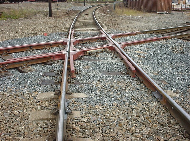
A diamond crossing allows two tracks to cross at grade without either track being directionally connected to the other. It consists of wing rails and crossing noses for both intersecting routes. A diamond crossing is not the same as a double-slip switch (DKV), which adds switch blades so trains can move between the intersecting tracks. The example in Figure 16.23 later in this chapter shows why a double-slip switch is a more complex component than a plain diamond crossing.
Figure 16.19 shows an actual plain diamond: follow the two crossing tracks and note the absence of switch blades connecting them.
16.2.5 Station layouts
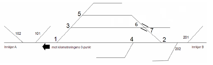
The arrangement of turnouts in a station or yard is described by a schematic plan, which shows the track topology without regard to the actual geometric configuration, and a geographical plan, which shows the actual geometry [68]. In Norwegian practice, switch numbering is tied to the direction toward the line's kilometre zero point, as illustrated in Figure 16.20.
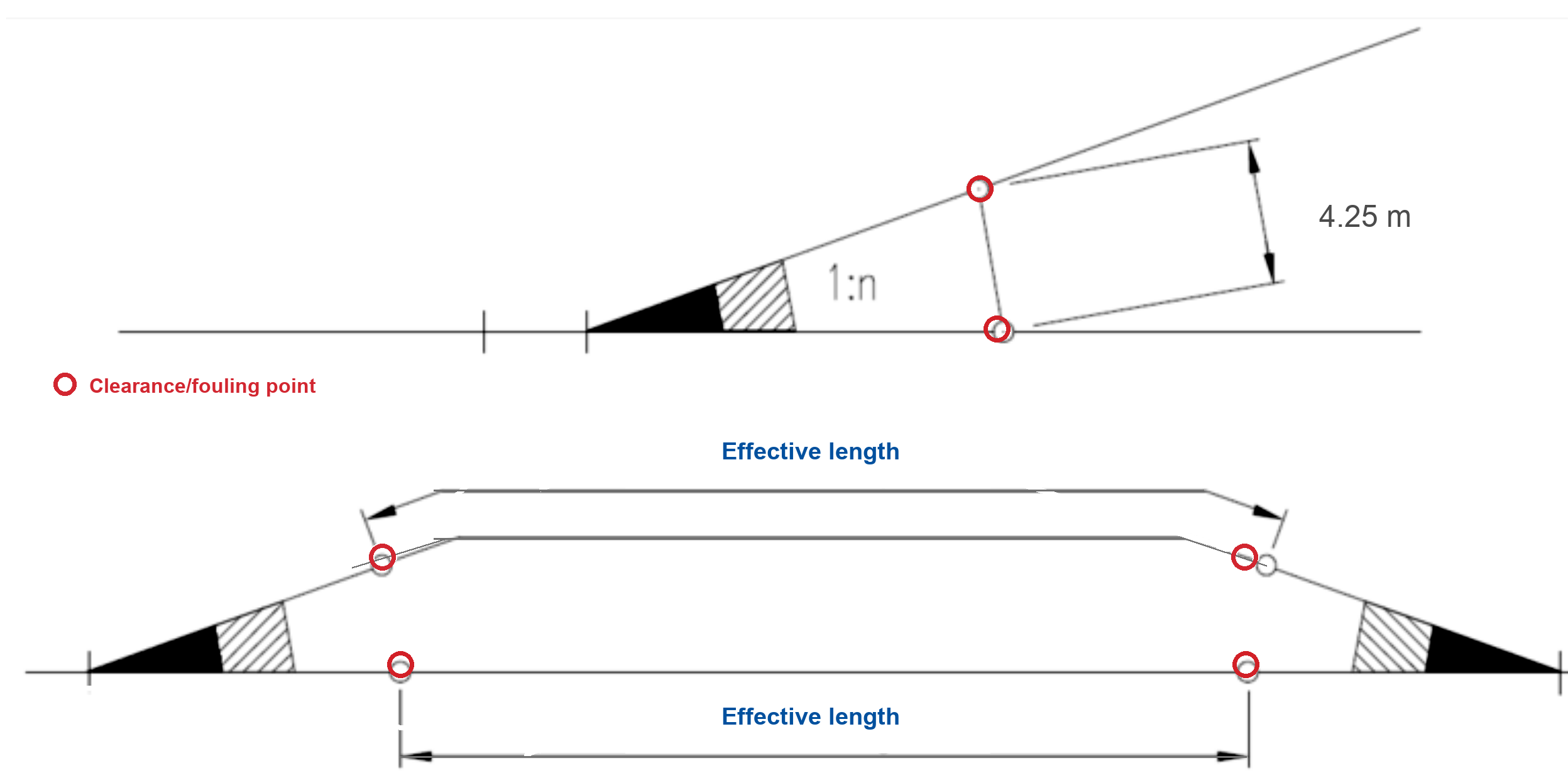
Track planning in complex stations requires careful attention to turnout geometry constraints, track separation distances (minimum clearances for adjacent platforms and tracks), gradient limitations through switch panels (turnouts are preferably placed on level or gently graded track, within the limits of the technical regulations), and the minimum track circuit lengths required for signalling. The effective length of a crossing track is governed by the clearance or fouling points rather than the physical rail length alone. As shown in Figure 16.21, these points define where vehicles can stand on one track without obstructing the adjacent route.
Turnouts should be on tangent track and must be there for axle loads above 25 t (TRV:02449). Placement in transition curves is prohibited; cant may not exceed 100 mm, or 80 mm for a hand-operated siding turnout (TRV:02450). Crossovers require tangent track or curves without cant (TRV:02452). The intervening length to an opposing turnout, curve or bridge follows the alignment calculation and is at least 6 m, subject to the stated exceptions (TRV:02451).
16.2.6 Curved turnouts
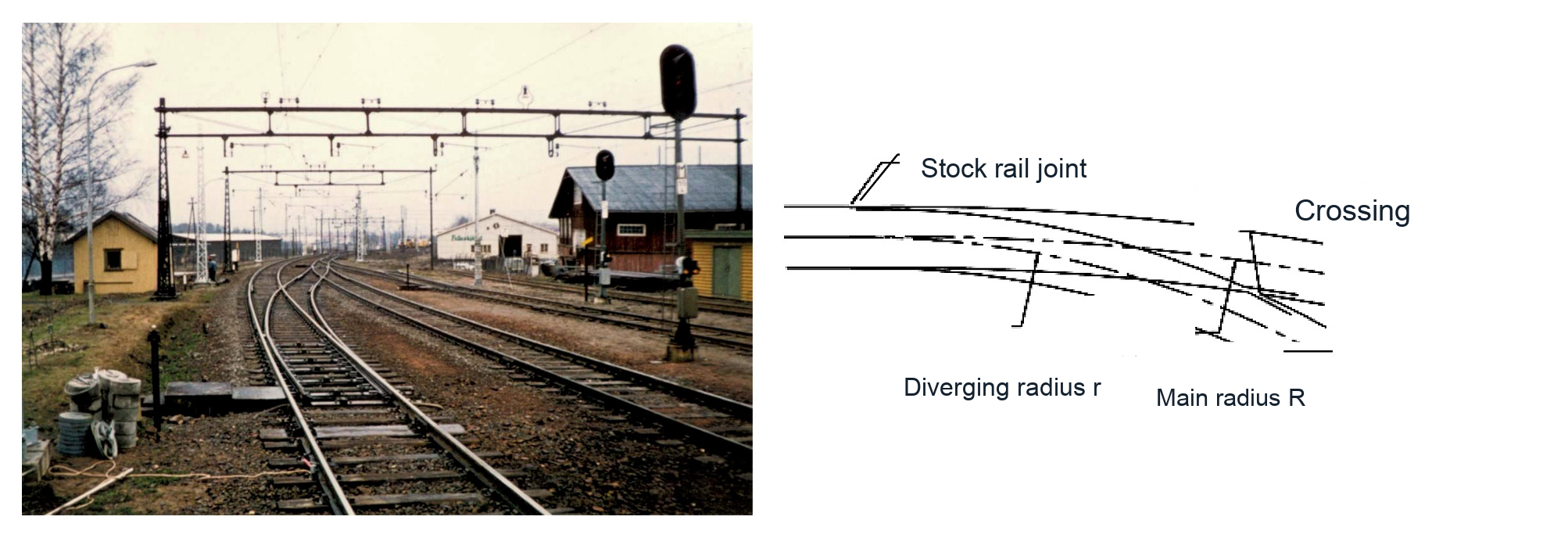
A curved turnout is a simple turnout with a long curve that has been bent so both the main route and the diverging route lie in a horizontal curve, as illustrated in Figure 16.22. Curved turnouts can solve difficult station-layout problems, but they are custom components, are harder to tamp and maintain, and are not suitable for every turnout type. In current Bane NOR rules, clothoid turnouts and turnouts with movable crossings are not curved [48].
Curvature \(\kappa\) means the change in direction per metre of track. Its magnitude is the inverse of radius: \(|\kappa|=1/R\), in \(\mathrm{m}^{-1}\). A tighter curve has greater curvature. Here the nominal right-hand diverging bend is positive, so a right-hand host curve adds curvature and a left-hand host curve subtracts it.
For preliminary layout calculations, take the nominal diverging bend as the positive direction and use positive radius magnitudes \(r_0\) and \(R_\mathrm{line}\). The signed diverging curvature is approximately \(\kappa_\mathrm{div}=1/r_0+1/R_\mathrm{line}\) when the host curve bends the same way, and \(\kappa_\mathrm{div}=1/r_0-1/R_\mathrm{line}\) when it bends the opposite way. The corresponding radius expressions are:
Equation 16.4 is written for \(R_\mathrm{line}>r_0\). If \(R_\mathrm{line}=r_0\), the net curvature is zero; if \(R_\mathrm{line}<r_0\), the diverging route bends opposite to the nominal turnout direction and the radius magnitude is obtained from \(R_\mathrm{line}r_0/\lvert R_\mathrm{line}-r_0\rvert\). The same-direction case gives a smaller diverging radius than the nominal turnout, so it can reduce the permissible diverging speed. Any effect on usable crossing-track length depends separately on the chosen placement and fouling points. These curvature combinations are preliminary estimates, not a substitute for the approved calculation and product geometry.
For a same-direction 1:12 R500 curved turnout, the minimum permitted curve radii are 600 m in the main route and 273 m in the diverging route (TRV:02707). Meeting this curving limit does not override the separate 300 m minimum for a newly designed passenger route. A cost/benefit review is required (TRV:02710). Thus a 1:12 R500 turnout curved into a same-direction R600 line curve fails the minimum-radius check for a new passenger route even before its speed is checked.
Worked example.
Consider a 1:12 R500 turnout, so the nominal diverging radius is \(r_0 = 500\) m. If it is curved into a same-direction line curve with \(R_\mathrm{line}=1000\) m, the effective diverging radius becomes
For an opposite-direction curved turnout in the same line curve,
Using Eq. 16.2 to calculate the allowable speed for the stated assumptions, with \(h_a=0\), \(I_{\max}=100\) mm \(=0.100\) m, \(S=1500\) mm \(=1.500\) m and \(g=9.81\,\mathrm{m/s^2}\), the nominal R500 geometry gives
whereas the same-direction curved case, retaining the unrounded radius in the calculation, gives
The same nominal turnout can therefore behave like a much tighter turnout when it is curved in the same direction as the main-line curve. The final permitted speed must still be taken from the technical regulations and local approval process, but the calculation shows why the radius effect has to be checked.
16.2.7 Slip switches
For new layouts, simple turnouts are preferred in main tracks. Slips and connections incorporating diamonds are selected only when space prevents simple turnouts (TRV:02690, TRV:02691). Asymmetric three-way turnouts must not be newly procured (TRV:08551).
A slip switch combines a diamond crossing with one or two turnout movements, allowing trains to cross from one track to the other within the diamond. Slip switches are used in space-constrained locations where separate simple turnouts cannot be accommodated.
Single-slip switch (EKV): Adds one curved connection between the intersecting routes. That connection can be traversed in either direction when the route is correctly set and secured.
Double-slip switch (DKV; DSS): Adds two curved connections. It provides four possible end-to-end paths: the two straight crossing paths and the two curved connections. A conventional internal double slip has four tongue pairs, two acute end crossings and two obtuse side crossings. This is a distinction between available paths, not a restriction to one-way train movement.
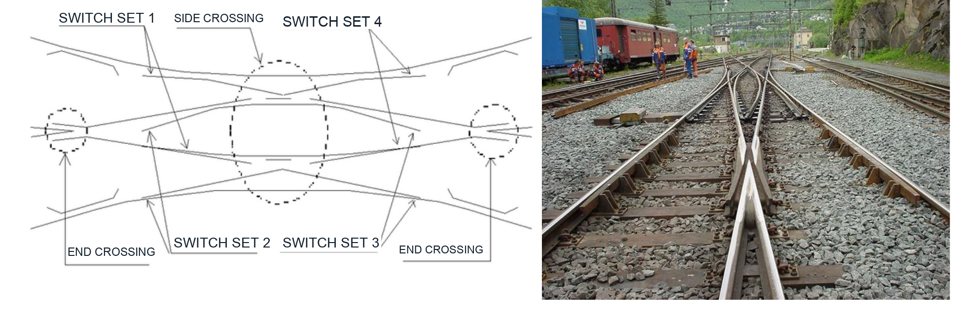
Slip switches are particularly common in large city stations (for example Oslo S), where multiple platform roads must connect through tight spaces [148, 130]. Their disadvantage is high maintenance intensity: a double-slip switch has four tongue pairs and four crossing assemblies in a single structure. The two side crossings each contain more than one point; counting all of these as four identical crossing noses is misleading. Drive, detection, guidance and support all require inspection.
16.3 Loading and maintenance
16.3.1 Changing contact and support
Switches and crossings can produce larger transient wheel–rail forces than plain track because the contact geometry and structural support change along the route:
-
Changing contact geometry: Wheel contact moves between stock rail and tongue, and between wing rail and crossing nose. The combined wheel and rail profiles determine the wheel-centre trajectory. Contact with the wing rail and nose can overlap; the visible flangeway is not a prescribed free-fall distance.
-
Changing structural support: Rail sections, pads, sleeper lengths and ballast conditions vary through the turnout. Changes in stiffness and local loss of sleeper support alter the dynamic response; support is not uniformly weaker throughout every turnout.
Speed, wheel profile, wear, wheelset flexibility and damping also influence the force history. A model of the complete wheelset and crossing can represent simultaneous contacts and structural deformation; see Xin et al. (2016) and Li et al. (2019).
Figure 16.24 shows the wheel-centre path used to connect forward speed with vertical velocity. The path represents the combined effect of contact geometry and deformation; it is not a sketch of an unsupported wheel falling through a gap.
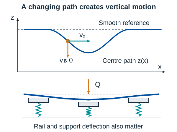
16.3.2 Impulse model
In a facing move, load transfers from the wing rail towards the crossing nose. A downward part of the wheel-centre trajectory followed by upward acceleration can create an impact. The actual trajectory depends on the contacting profiles and their deflections. The following prescribed-path model illustrates the role of velocity change without claiming that the wheel becomes airborne.
Take upward vertical velocity as positive. If the assumed wheel-centre path descends by \(\Delta h>0\) over a horizontal length \(L>0\), its vertical velocity before an idealised stopping pulse is approximately
Here \(v_x\) is train speed, \(L\) is the prescribed trajectory length, and \(\Delta h\) is the prescribed descent of the wheel centre. Neither \(L\) nor \(\Delta h\) is inferred from the visible flangeway. For the worked example, assume \(v_{z,\mathrm{after}}=0\), so \(\Delta v_z\approx v_x\Delta h/L\). This represents removal of the downward velocity, not a complete reversal with rebound.
Figure 16.25 separates the descent along length \(L\) from the stopping pulse of duration \(\Delta t\). The descent determines the incoming vertical velocity; the pulse removes that velocity.
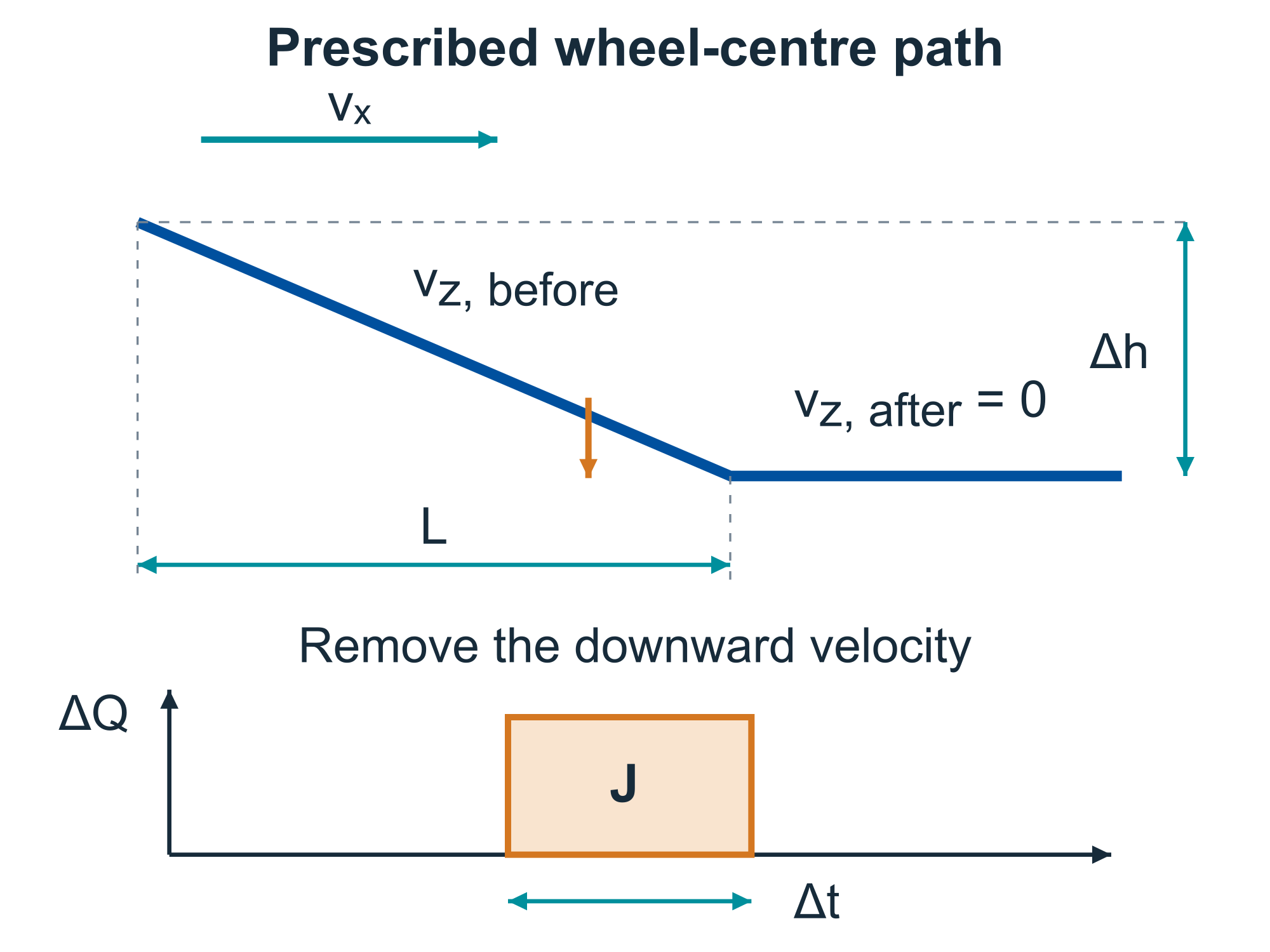
For one wheel, let \(Q(t)\) denote the total vertical rail contact force, including both wing-rail and nose contributions if they act simultaneously. Taking the other vertical forces as approximately constant during the short pulse gives
The unsprung mass \(m_\mathrm{u}\) is the mass represented at the wheel being analysed. For this simplified one-wheel model it is supplied as a separate input; it is not automatically the mass of the entire wheelset. The static wheel load also includes load transmitted from the sprung vehicle, so \(Q_\mathrm{static}\ne m_\mathrm{u}g\). A coupled model or measurement is needed to determine the actual force history and peak.
A movable crossing closes the running-edge opening for the selected route and can make the load transfer smoother. It does not remove all profile irregularity, support variation or dynamic loading. A quantitative comparison with a fixed crossing requires the actual geometry and operating conditions; no fixed reduction follows from the crossing type alone. This distinction is consistent with the geometry-dependent response of the swing-nose crossing studied by Zhang et al. (2025).
16.3.3 Average and peak forces
In this chapter, the dynamic amplification factor is defined using the peak total vertical contact force for one wheel:
The numerator is the maximum of a measured or modelled force history. By contrast, \(Q_\mathrm{static}+\Delta Q_\mathrm{avg}\) is a mean total over the selected pulse interval. Dividing this mean total by the static load does not establish the peak amplification factor.
Figure 16.26 compares two idealised force pulses with equal area above the static baseline and equal duration. Their average additional force is equal, but the triangular pulse has twice the peak increment. This explains why impulse alone cannot determine the peak force.
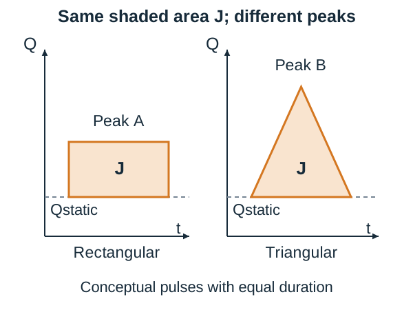
There is no universal factor assigned here to a new, worn, fixed or movable crossing. Numerical factors used in exercises are explicitly supplied assumptions. For an installed turnout, the influences in Table 16.2 must be represented in the measurements or validated model before a peak factor is used.
| Influence | What the assessment must represent |
|---|---|
| Contact geometry | Wheel and rail profiles, transfer position, wear and local profile changes |
| Structural support | Rail and pad stiffness, sleeper support, ballast condition and damping |
| Vehicle and operation | Speed, wheel loading, wheelset flexibility and participation of both wheels |
| Force definition | The selected wheel, peak of the total force history, and static reference load |
16.3.4 Worked example: average force
Consider one wheel with static load \(Q_\mathrm{static}=80\) kN and unsprung mass \(m_\mathrm{u}=650\) kg. The train speed is \(v_x=80\) km/h. The assumed wheel-centre path descends by \(\Delta h=2.5\) mm over length \(L=0.18\) m; the downward velocity is then removed during a pulse of duration \(\Delta t=2.0\) ms. These are teaching inputs, not acceptance limits or calibrated crossing properties.
Step 1: convert the inputs. Keep the conversion unrounded until the final force is reported.
Step 2: calculate the velocity change. Apply Eq. 16.5 with zero vertical velocity after the pulse.
Step 3: calculate the average additional force. The impulse is the area above the static-load baseline. Divide it by the pulse duration, using Eq. 16.6.
Step 4: add the static wheel load. The mean total force over the same pulse is
The travel time \(L/v_x=8.1\) ms is different from the assumed 2.0 ms stopping pulse. The descent is prescribed by the wheel trajectory; it is not a gravity-only free-fall calculation. The peak force is still unknown.
Smaller trajectory change
Change only the descent to \(\Delta h=1.0\) mm. Keeping the speed, mass, length and pulse duration unchanged gives
The smaller descent reduces the vertical velocity change and therefore the average additional force. The 2.5 mm and 1.0 mm cases represent two prescribed trajectories; they are not performance values assigned to fixed and movable crossings. Figure 16.27 illustrates the comparison.
Changing one input at a time. A larger unsprung mass increases the average additional force. A larger static wheel load increases \(Q_\mathrm{mean}\), while leaving \(\Delta Q_\mathrm{avg}\) unchanged when the other inputs are fixed. A longer pulse spreads the same impulse over more time, reducing its average force. This distinction is the basis for comparing the assignment cases.
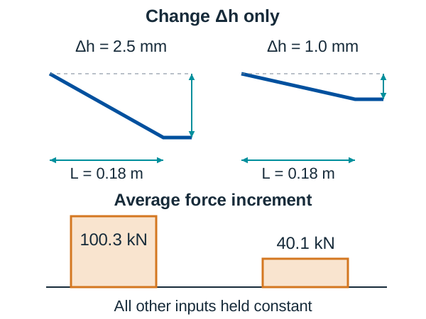
Dynamic force measurements and validated vehicle–track models can support condition assessment. Their interpretation should be combined with profile, damage and support observations before maintenance or renewal is selected.
16.3.5 Maintenance
Switches and crossings require intensive maintenance because of their geometric complexity, the dynamic forces at the crossing nose, and the wear of moving parts. The key maintenance activities are:
Tongue inspection and lubrication: Inspect the tongue–stock rail fit, sliding surfaces and roller devices for wear, contamination and correct operation. Use approved lubricant on the specified surfaces and follow the supplier’s instructions and intervals. The current rules specifically exclude Cogislide lubrication-free slide plates from lubrication (TRV:07769, TRV:07771, TRV:07772, TRV:07773). The wheel running surface is not a lubrication target. Verify closed-tongue contact against the applicable maintenance tolerance.
Crossing nose inspection: Inspect the crossing nose and wing rails for plastic deformation, wear, cracking and spalling. Combine visual examination with the nondestructive inspections specified for the component, and with profile, wear and geometry measurements. Use the installed component's maintenance documentation and the prescribed measurement locations. Record the finding and the required follow-up before selecting repair or renewal.
Profile correction: Grinding of tongues and crossing components preserves the intended contact geometry. Use the approved profile, material-specific method and repair procedure. New austenitic manganese crossings work-harden under traffic and must be inspected and ground to correct the accompanying deformation, following the traffic-based programme in TRV:07762. Grinding, milling or build-up welding are not interchangeable remedies for every defect; the material, damage and approved procedure govern selection.
Point machine maintenance: Inspect and test the installed mechanism at the prescribed intervals to verify movement, locking and position detection. Check the connections to the signalling system and the condition of cables and rods. Test heater function before the winter season.
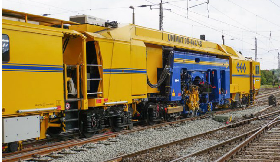
Geometry tamping: Specialised turnout tamping restores level, alignment and ballast support beneath long, non-uniform sleepers. Work can affect several connected routes, so their geometry must be controlled together. Lifting and tine placement must avoid damage to drives, rods and crossing components. Recheck the required track geometry and operating function after the work.
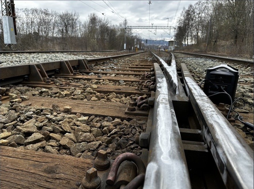
Figure 16.28 shows three representative views. The first two panels show a crossing in track and a cast crossing component. They support component recognition; the photographs alone do not establish a named defect or its severity. Such inspections are intended to detect surface damage, including batter, metal flow and local cracking, before it develops into a critical defect. The third panel shows switch-panel tamping, which is slower than plain-line tamping because the machine must lift and pack around long sleepers, rodding and the point machine without damaging them.
Figure 16.28(a) shows a crossing in track, 16.28(b) shows a cast crossing component, and 16.28(c) shows turnout tamping. These views connect the inspected components to the maintenance work.
Inspection response depends on the component and the classified crack or surface flaw. In tongues, groups 0 and 1 require immediate repair (TRV:04421). In fixed crossings, group 0 requires immediate repair and group 1 repair within one month (TRV:04428, TRV:04429). For a movable nose, group 1 requires repair within two weeks, with speed limited to 40 km/h meanwhile (TRV:08234). These selected requirements were checked on 4 November 2026. The full defect classification and applicable procedures govern classification and operational protection; a photograph alone is not an acceptance test.
Three connected decisions
- Operation: the components must guide the wheels, move correctly and provide the required locking and position indications.
- Geometry: route curvature and turnout construction determine the space needed and the allowable speed.
- Condition: contact profiles, support and operating equipment determine the forces and maintenance required in service.
Assignments
Assignment 1: Components and functions
Sketch a typical right-hand turnout with a fixed crossing, viewed from above. Label all panels and main components. State each component's function in one to two short sentences.
Assignment 2: Curvature and allowable speed
Use a right-hand turnout with a nominal diverging radius of 500 m. The main route follows the host curve. Take right-hand curvature as positive and use the approximate method from the lecture.
| Case | Host-curve direction | Host radius [m] |
|---|---|---|
| A | Right, same direction as the turnout | 1000 |
| B | Right, same direction as the turnout | 750 |
| C | Left, opposite direction to the turnout | 1000 |
Speed inputs (exercise assumptions): zero cant, maximum cant deficiency 100 mm, effective contact spacing 1500 mm and gravity 9.81 m/s².
(a) Calculate the curvature and radius of the diverging route in each case.
(b) Calculate the allowable speed for each diverging route from the supplied cant-deficiency limit. Give radii and speeds to one decimal place.
(c) Briefly explain how the host-curve radius and curve direction affect the diverging radius and allowable speed.
Assignment 3: Average impact force
Use the lecture's one-wheel impact model with train speed \(v_x=80\,\mathrm{km/h}\), descent length \(L=0.18\,\mathrm{m}\) and pulse duration \(\Delta t=2.0\,\mathrm{ms}\) for every case.
| Case | Unsprung mass \(m_{\mathrm{u}}\) [kg] | Descent \(\Delta h\) [mm] | Static load \(Q_{\mathrm{static}}\) [kN] |
|---|---|---|---|
| A | 650 | 2.5 | 80 |
| B | 780 | 2.5 | 80 |
| C | 650 | 1.0 | 80 |
| D | 650 | 2.5 | 100 |
(a) Calculate the average additional force \(\Delta Q_{\mathrm{avg}}\) and mean total force \(Q_{\mathrm{mean}}\) for A–D. Present both results in kN.
(b) Compare B, C and D with A. Briefly explain the effect of changing the unsprung mass, descent or static wheel load while keeping the other inputs fixed.